


NAVMAN
Tracker
5507/5607
Installation and
Operation Manual
Chartplotters
w w w . n a v m a n . c o m
IMPORTANT SAFETY INFORMATION
Please read carefully before installation and use.
DANGER |
This is the safety alert symbol. It is used to alert you to |
|
potentialpersonalinjuryhazards,Obeyallsafetymessages |
||
|
|
that follow this symbol to avoidpossible injury or death. |
|
|
|
! |
WARNING |
WARNINGindicatesapotentiallyhazardoussituationwhich, |
if not avoided, could result in death or serious injury |
||
|
|
|
! |
CAUTION |
CAUTIONindicatesapotentiallyhazardoussituationwhich, |
if not avoided, could result in minor or moderate injury. |
||
|
|
|
CAUTION |
CAUTION used without the safety alert symbol indicates a |
|
potentially hazardous situation which, if not avoided, may |
||
|
|
result in property damage. |
|
|
|
FCCStatement
Note: This equipment has been tested and found to comply with the limits for a Class B digital device, pursuant to Part 15 of the FCC Rules. These limits are designed to provide reasonable protection against harmful interference in a normal installation. This equipment generates, uses and can radiate radio frequency energy and, if not installed and used in accordance with the instructions, may cause harmful interference to radio communications. However, there is no guarantee that interference will not occur in a particular installation. If this equipment does cause harmful interference to radio or television reception, which can be determined by turning the equipment off and on, the user is encouraged to try to correct the interference by one or more of the following measures:
Reorient or relocate the receiving antenna.
Increase the separation between the equipment and receiver.
Connect the equipment into an output on a circuit different from that to which the receiver is connected.
Consult the dealer or an experienced technician for help.
A shielded cable must be used when connecting a peripheral to the serial ports.
Industry Canada
Operation is subject to the following two conditions: (1) this device may not cause interference, and (2) this device must accept any interference, including interference that may cause undesired operation of the device.

Important
ItisyoursoleresponsibilitytoinstallanduseNAVMAN’sinstrumentandGPSantennainamannerthatwill notcauseaccidents,personalinjuryorpropertydamage. Alwaysobservesafeboatingpractices.
Thechoice,location,angleandinstallationoftheinstrument&GPSantennaarecriticaltoperformance ofthesystemasintended. Followinstructionsinthismanualcarefully. Ifindoubt,consultyourNAVMAN dealer.
Ensurethatanyholescutareinasafepositionandwillnotweakentheboat’sstructure. Ifindoubt,consult aqualifiedboatbuilder.
GlobalPositionSystem: TheglobalPositionSystem(GPS)isoperatedbytheU.S.Governmentwhichis solelyresponsibleforitsoperation,accuracyandmaintenance.TheGPSissubjecttochangeswhichcould a ecttheaccuracyandperformanceofallGPSequipmentanywhereintheworld,includingthe5507/5607 andTRACKFISH.Toreducetheriskofmisusingormisinterpreting the5507/5607andTRACKFISH,youmust readandunderstandallaspectsofthisInstallation&OperationManual.Wealsorecommendthatpractice alloperationsusingthebuilt-insimulatorbeforeusingthe5507/5607orTRACKFISH.
ElectronicChart: Theelectronicchartusedby5507/5607orTRACKFISHisanaidtonavigationdesigned tosupplement,notreplaceo cialgovernmentcharts.Onlyo cialgovernmentchartssupplementedby noticestomarinerscontaintheinformationrequiredforsafeandprudentnavigation,Alwayssupplement theelectronicinformationprovidedby5507/5607orTRACKFISHwithotherplottingsourcessuchas observations,depthsoundings,radarandhandcompassbearings.Shouldtheinformationnotagree,the discrepancymustberesolvedbeforeproceedinganyfurther.
AIS:TheAISfeaturesonthischart-plotteraredesignedasasafetyaidonlyanddonotguaranteesafety atsea.AIStransmissionismandatoryonsome,butnotall,vessels. Youshouldcheckyourlocallawsand regulationsforrequirementsinyourarea.Asaresultofdi erentlegalrequirements,di erentvesselsizes anduses,youshouldnotassumethatyourAISequippedchart-plotterwillshowthelocationofALLvessels
inyourarea.Carefulprudence,judgement,andsafenavigationpracticesshouldbealwaysbeexercised.AIS shouldbeusedtocomplementradar,butAISisnotasubstituteforradar.
FuelComputer: Donotrelyonthefuelcomputerasthesolesourceofinformationregardingavailable fuelonboard.Fueleconomycanchangedrasticallydependingonboatloadingandseaconditions.Fuel Computerinformationshouldbesupplementedbyvisualorotherchecksofthefuelload.Thisisnecessary duetopossibleoperatorerrorssuchasforgettingtoresetthefuelusedwhenfillingthetank,runningthe enginewiththeFuelComputernotswitchedon,oronotheroperatoractionsthatmayrenderthedevice inaccurate.Alwayscarryadequatefuelonboardfortheintendedtrip,plusareservetoallowforunforeseen circumstances.
Failuretoadheretothesewarningsmayleadtodeath,seriousinjuryorpropertydamage.NAVMAN disclaimsallliabilityforinstallationoruseofthisproductthatcausesorcontributestodeath,injury orpropertydamageorthatviolatesanylaw.
AsNAVMANiscontinuouslyimprovingthisproductweretaintherighttomakechangestotheproductat anytimewhichmaynotbereflectedinthisversionofthemanual. PleasecontactyournearestNAVMAN o ceifyourequireanyfurtherassistance.
GoverningLanguage: Thisstatement,anyinstructionmanuals,userguidesandotherinformationrelating totheproduct(Documentation)maybetranslatedto,orhavebeentranslatedfrom,anotherlanguage (Translation). IntheeventofconflictbetweenanyTranslationsoftheDocumentation,theEnglishlanguage versionoftheDocumentationwillbetheo cialversion.
Copyright©2006NAVMANNewZealand. Allrightsreserved. NAVMANisaregisteredtrademarkof NAVMANNewZealand.
The5507/5607issetupwithdefaultunits.Tochangetheunits,seesection15-9
4NAVMAN TRACKER 5507/5607 Installation and Operation Manual

Contents
1Introduction.......................................................................................................................................... |
9 |
1-1Overview.........................................................................9 1-2Cleaningandmaintenance .......................................................9 1-3Plug-incards .....................................................................9 1-4Removingandreplacingthedisplayunit ........................................10
2BasicOperation.................................................................................................................................... |
11 |
2-1Usingthekeys...................................................................11 2-2Usingthemenus ................................................................12 2-3Turningonandoff/autopower.................................................12 2-4Backlightandnightmode.......................................................13 2-5Manoverboard(MOB)...........................................................13 2-6Alarms ..........................................................................13 2-7Simulatemode ..................................................................14 2-8Themainwindows ..............................................................14
3Navigation:Chart................................................................................................................................. |
19 |
3-1Overviewofnavigating..........................................................19 3-2Chartwindow ...................................................................21 3-3Distanceandbearingcalculator .................................................23 3-4Projectedcourse ................................................................23 3-5Tracksandtracking..............................................................24
4Navigation:Highwaywindow.............................................................................................................. |
25 |
5Navigation:Waypoints......................................................................................................................... |
25 |
5-1Waypointswindow.............................................................. |
26 |
5-2Managingwaypoints............................................................ |
26 |
6Navigation:Routes.............................................................................................................................. |
28 |
6-1Routeswindow.................................................................. |
28 |
6-2Managingroutes ................................................................ |
29 |
7Satellites............................................................................................................................................. |
31 |
7-1Satellitewindow................................................................. |
32 |
8Gaugeswindow ................................................................................................................................... |
32 |
NAVMAN TRACKER 5507/5607 Installation and Operation Manual |
5 |
9Datawindow ....................................................................................................................................... |
33 |
10Fuelfunctionsanddisplay.................................................................................................................. |
34 |
10-1Whatthefuelcomputerdoes ..................................................34 10-2Fuelwindow ...................................................................34 10-3Whenyouaddorremovefuel..................................................35 10-4Lowfuelalarm .................................................................36 10-5Boatspeedsensors.............................................................36 10-6Fuelconsumptioncurves ......................................................38 10-7Calibration .....................................................................40
11Tideswindow..................................................................................................................................... |
41 |
12Usercardwindow............................................................................................................................... |
42 |
13AIS ..................................................................................................................................................... |
43 |
13-1ViewingAISVessels ............................................................ |
44 |
13-2DangerousVessels ............................................................. |
44 |
13-3AISWindows................................................................... |
45 |
14DSC/Buddytrackwindows.................................................................................................................. |
46 |
14-1Thewindows................................................................... |
46 |
14-2Usingthewindows............................................................. |
47 |
15Settingupthe5507/5607 ................................................................................................................... |
48 |
15-1Setup >System ................................................................50 15-2Setup >Chart .................................................................51 15-3Setup >GPS ...................................................................54 15-4Setup>Fuel ...................................................................55 15-5Setup>Track...................................................................56 15-6Setup>AIS.....................................................................57 15-7Setup>Logs ...................................................................57 15-8Setup>Alarms.................................................................58 15-9Setup>Units...................................................................59 15-10Setup>Comms...............................................................59 15-11Setup>Calibrate..............................................................60 15-12Setup>Time..................................................................61 15-13Setup>Favorites..............................................................62 15-14Setup>Simulate..............................................................62
6NAVMAN TRACKER 5507/5607 Installation and Operation Manual
16Installation........................................................................................................................................ |
63 |
16-1Installation:Whatcomeswiththe5507/5607 ...................................63 16-2Installation:OptionsandAccessories...........................................63 16-3Installation:Thedisplayunit....................................................65 16-4Installation:Power/Datacable..................................................66 16-5Installation:GPSantenna.......................................................67 16-6Installation:NAVMANpetrol/gasolinesensors..................................67 16-7Installation:NAVMANdieselsensors............................................68 16-8Installation:SmartCraft™ .......................................................68 16-9Installation:OtherNavBusinstruments.........................................69 16-10Installation:OtherNMEAinstruments.........................................70 16-11Installation:Setupandtest ....................................................70
AppendixA-Specifications..................................................................................................................... |
71 |
AppendixB-Troubleshooting................................................................................................................. |
73 |
B-1GeneralProblems ............................................................... |
73 |
B-2GPSnavigationproblems........................................................ |
74 |
B-3Fuelconsumptionproblems..................................................... |
75 |
AppendixC-Glossaryandnavigationdata.............................................................................................. |
76 |
NAVMAN TRACKER 5507/5607 Installation and Operation Manual |
7 |

Quick reference
Feature |
Type |
See |
Requires |
|
|
|
|
General |
How to use the keys and displays |
2 |
|
|
Troubleshooting |
Appendix B |
|
|
Simulate mode |
2-7 |
|
|
Glossary of special names |
Appendix C |
|
|
Specifications |
Appendix A |
|
|
|
|
|
MOB |
Man overboard key |
2-5 |
|
|
|
|
|
Navigation |
Overview of how to navigate |
3-1 |
GPS fix |
|
Finding the boat’s position on the chart |
3-2 |
|
|
Navigate to any point or to a waypoint |
3-1 |
|
|
Navigate along a route |
3-1 |
|
|
Projected course: An estimate of progress |
3-4 |
|
|
Tracks: records of where the boat has been |
3-5 |
|
|
GPS receiver status |
7 |
|
|
Saving and loading data with a user card |
12 |
User card |
|
|
|
|
Chart data |
Chart features (built in world chart) |
3-2 |
|
|
Chart details |
3-2-4 & 5 |
C-MAP™ chart |
|
Tides at a port |
11 |
C-MAP™ chart |
|
AIS |
13 |
|
|
|
|
|
Alarms |
Built in alarms |
2-6 |
|
|
SmartCraft™ engine alarms |
1-1 |
SmartCraft™ |
|
|
|
|
Boat data |
Data at top of main displays |
2-8-3 |
|
|
Compass at top of main displays |
2-8-4 |
|
|
Dedicated data window |
9 |
|
|
|
|
|
Fuel |
Fuel computer, petrol/gasoline engine |
10 |
Fuel sensors |
|
Fuel computer, SmartCraft™ engines |
10 |
SmartCraft™ |
|
Fuel computer, diesel engine |
10 |
Diesel sensors |
|
What to do when you add or remove fuel |
10-3 |
|
|
|
|
|
8NAVMAN TRACKER 5507/5607 Installation and Operation Manual

1 Introduction
1-1Overview
The NAVMAN 5507/5607 is a compact, rugged, highly integrated marine chartplotter. It is easy to use and has an easy to read color display. Complex functions can be performed with a few key presses, taking the hard work out of boating.
This manual covers:
5507/5607
Color display, external GPS antenna.
The available functions, displays and setup menus depend on the optional sensors and instruments that are installed:
1The Fuel functions require optional petrol/gasoline, diesel or SmartCraft™ fuel sensors to be installed and set up.
2SmartCraft™ engine functions require a SmartCraft™ system to be installed. For information on using SmartCraft™, see the
SmartCraft™GatewayInstallationand
OperationManual.
3The 5507/5607 can send data to other instruments, such as an autopilot, and receive data from other instruments.
4AIS functions require an optional AIS receiver to be installed.
For information on installing options, see section 16-2.
This manual describes how to install and operate the 5507/5607. Special terms are explained in Appendix C. For maximum benefit, please read this manual carefully before installing and using the unit. For more information on this instrument and other NAVMAN products, go to our website, www.navman.com.
1-2Cleaningandmaintenance
The 5507/5607 screen is covered by a proprietary anti-reflection coating. To avoid damage, clean the screen only with a damp cloth and mild detergent when dirty or covered in sea salt. Avoid abrasive cleaners, petrol or other solvents. If a plug-in card gets dirty or wet, clean it with a damp cloth or mild detergent.
Tooptimize performance, avoid walking on or jamming cables and connectors.
Push the dust cover over the display when the 5507/5607 is turned off.
1-3Plug-incards
The 5507/5607 can use two kinds of plug-in card:
1C-MAP™ chart cards have chart details required for navigating in a particular region. When a chart card is plugged in, the extra details automatically appear on the 5507/5607 chart window.
The 5507/5607 can use NT, NT+, NT-MAX and NT-MAX2 cards.
2C-MAP™ user cardsare used to store navigation data. Each user card expands the 5507/5607 memory and allows the data to be transferred to another 5507/5607 easily (see section 12).
Note: The older 5 volt user cards are not supported.
NAVMAN TRACKER 5507/5607 Installation and Operation Manual |
9 |
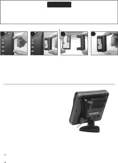
Changingtheplug-incard
CAUTION
Handle plug-in cards carefully. Keep them in their protective cases when not plugged into the 5507/5607.
Keep the holder in place in the 5507/5607 at all times to prevent moisture from entering the card compartment.
Goldcontactsunderhere
12
Turn the 5507/5607 off (see section 2-3).
Pull the card holder out of the 5507/5607 and pull any card out of holder.
Put the card in its case.
34
Card
Holder
Push new card into holder. Ensure the gold contacts are on the outer edge and underneath (see above).
Keep the card’s case.
Push card holder fully into 5507/5607
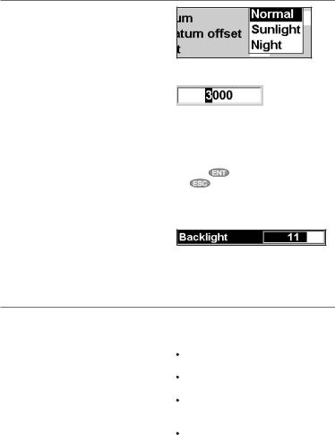
1-4Removingandreplacingthedisplayunit
If the display unit is bracket mounted then the display unit can easily be removed and replaced for security or protection.
Removing the display unit:
1Turn the display unit off (see section 2-3) and put the dust cover on.
2Loosen the knob on the mounting bracket and lift the unit off the bracket.
3Unplug the connectors from from the display unit, turning each locking collar anticlockwise. Push the attached dust covers
over the connectors. |
Knob |
Mounting |
|
4 Store the display unit in a dry clean place, |
bracket |
||
|
|||
|
|
||
such as the optional NAVMAN carry bag. |
|
|
Replacing the display unit
1Remove the dust covers from the connectors. Plug the connectors into the back of the display unit:
Match the connector’s color to the socket color.
Insert each connector and turn the locking collar clockwise until it is finger tight.
Nothing will be damaged if a cable is plugged into the wrong socket by mistake.
2Hold the display unit in place on the mounting bracket. Adjust the tilt of the display for best viewing, then hand tighten the knob on the mounting bracket. Remove the dust cover.
10 |
NAVMAN TRACKER 5507/5607 Installation and Operation Manual |
2 Basic Operation
Overviewofthekeys
 ESCAPE - Go back to an earlier menu or display. In chart mode, centres chart at boat’s position.
 DISPLAY - Show a menu of the main displays. To go to a display, select it from the menu (see section 2-8).

 CURSOR KEYS - to move the cursor or the selection highlight.
 MENU - Show a menu of the options for the current window.
Press  again to display the Setup menu (see section 15).
 ENTER - Start an action or accept a change.

 ZOOM - Zoom in or out to display different areas and detail on the chart.
 WAYPOINT - Create an instant waypoint at the boat position (see section 5-2-1).
 MOB - (Man Overboard, see section 2-5).
 POWER - Turn 5507/5607 on and off (see section 2-3); adjust the backlighting (see section 2-4).
2-1Usingthekeys
In this manual:
Press means to push the key for less than a second. Hold means to hold the key down.
The internal beeper beeps when a key is pressed (to disable or enable the beep, see section 15-1).
NAVMAN TRACKER 5507/5607 Installation and Operation Manual |
11 |
2-2Usingthemenus
Operate the 5507/5607 by selecting items from menus. Items can be submenus, commands or data.
Selecting a submenu
A after a menu item indicates a submenu, for example Chart
  . Press
  or
or  to move the highlight to the submenu, then press
  .
.
Starting a command
Press  or
or  to move the highlight to the command, for example Goto cursor, then press
  .
.
Changing data
First press  or
or  to move the highlight to the data to change, then:
a)To change a tick box
 means On or Yes
 means Off or No.
Press  or
or  to change the tick box. b) To select an option
1Press  to display the menu of options.
2Press  or
or  to move the highlight to the option you want, then press
  .
.
c) To change a name or number:
1Press  to display the name or number:
2Press  or
or  to select a letter or digit to change. Press
  or
or  to change the letter or digit.
Repeat this to change other letters or numbers.
3 Press |
to accept the new value. Or press |
|
to ignore the changes. |
d) To change a slider value
Press  to decrease the value or
  to increase the value.
2-3Turningonandoff/autopower
Turning on manually
If the 5507/5607 is not wired for auto power, press
 to turn the unit on. If necessary, adjust the display to be easy to read (see section 2-4).
Note: If the 5507/5607 is not wired for auto power then the 5507/5607 does not record engine hours and might not record fuel consumption (see section 16-4).
Turning off manually
If the 5507/5607 is not wired for auto power or if
the ignition switch is off, hold down  until the display turns off.
Auto power
If the 5507/5607 is wired for auto power (see section 16-4), then:
The 5507/5607 automatically turns on when you turn the boat’s ignition switch on.
You can not turn the 5507/5607 off while the ignition switch is on.
If Auto power off (see section 15-1) is  , the 5507/5607 automatically turns off when you turn the boat’s ignition switch off.
If Auto power off (see section 15-1) is  , the 5507/5607 stays on when you turn the boat’s ignition switch off. You can now turn the 5507/5607 off manually.
12 |
NAVMAN TRACKER 5507/5607 Installation and Operation Manual |
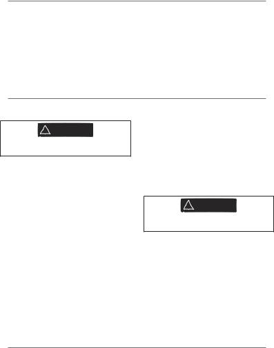
2-4Backlightandnightmode
To go to the Backlight display, press  briefly. When you have finished, press
  .
.
Backlight
The display and keys are backlit. To change the backlight level, select Backlight, then press
 to dim or
  to brighten.
 Tip: Press
  twice to give the brightest screen, with maximum backlight and Night mode off.
Night mode
Night mode sets the palette for all displays.  Normal palette, for daytime
 A palette optimised for night time.
To change mode, select Night mode, then press
 . To change only the chart palette, see section 15-2.
2-5Manoverboard(MOB)
The MOB feature saves the boat’s position and then navigates back to this point.
! WARNING
MOB will not work if the 5507/5607 does not have a GPS fix.
1Press  .
.
The 5507/5607 stores the boat’s position as a waypoint called MOB.
2The 5507/5607 changes to the chart window, with the MOB waypoint at the centre of the chart.
The chart zooms in for accurate navigation. If the chart can not show the required small scale, the 5507/5607 changes to plotter mode (a white display with crosshatching and no chart details, see section 15-2).
3The 5507/5607 sets the MOB waypoint to be the destination to navigate to.
If the NMEA output (autopilot) is off (see section 15-10) use the 5507/5607 to manually navigate to the destination MOB waypoint (see sections 3-1-1 and 3-1-2).
If the NMEA output (autopilot) is on, the 5507/5607 asks if the autopilot is active. Select:
No: Use the 5507/5607 to manually navigate to the destination MOB waypoint (see sections 3-1-1 and 3-1-2).
Yes: The 5507/5607 asks if the boat is to go to the MOB waypoint.
Select:
Yes: to immediately start navigating to the MOB waypoint.
! WARNING
This might result in a sudden and dangerous turn.
No: disengage the autopilot; then use the 5507/5607 to manually navigate to the
destination MOB waypoint (see sections 3-1-1 and 3-1-2).
To cancel MOB or set another MOB
1 Press  again to display a menu.
2Select an option from the menu.
 Tip: The MOB waypoint remains on the chart after the MOB has been cancelled. To delete the MOB waypoint, see section 5-2-5.
2-6Alarms
When the 5507/5607 detects an alarm condition, it displays a warning message on the display, the internal beeper sounds and any external beepers or lights operate.
Press  to clear the alarm. The alarm will sound again if the alarm condition occurs again.
The 5507/5607 has user settable alarms plus an alarm for loss of GPS fix (see section 15-8).
NAVMAN TRACKER 5507/5607 Installation and Operation Manual |
13 |
2-7Simulatemode
In Simulate mode, the 5507/5607 ignores data from the GPS antenna and other transducers and sensors and the 5507/5607 generates this data itself. Otherwise, the 5507/5607 functions normally.
There are two simulate modes:
Normal: Allows a user to become familiar with the 5507/5607 off the water.
Demo: Simulates a boat moving along a route and automatically displays different 5507/5607 functions.
To start and stop Simulate mode, and for more
information, see section 15-13. In simulate mode, Simulate or Demo flashes at the bottom of
the display.
! WARNING
Never have Simulate mode on when the 5507/5607 is navigating on the water.
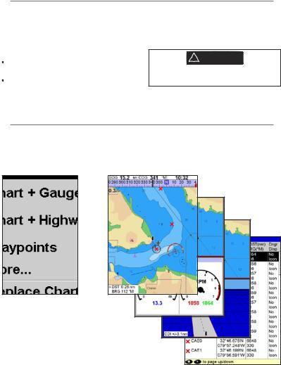
2-8Themainwindows
The display menu allows quick access to the main windows and favorites. Full-screen Chart is at the top of the menu followed by favorites. Other windows are available from the More… sub menu.
Note:
The windows available depend on the optional sensors and instruments that are installed (see section 1-1).
14 |
NAVMAN TRACKER 5507/5607 Installation and Operation Manual |

Note: The windows below the menu divider can only be shown full screen without a data header. (see section 2-8-3).
NAVMAN TRACKER 5507/5607 Installation and Operation Manual |
15 |
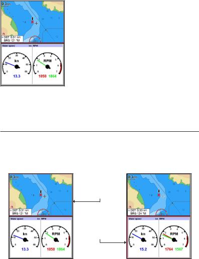
2-8-1Multiwindowdisplays
The 5507/5607 can show two windows at once.
Adding a window to the display
Press  , select Add window and select a window to add. The 5507/5607 automatically rearranges the display to show the new window.
Changing window size
1Press  and select Split ratio.
2Press  or
or  to change the height of the windows.
Note: Some windows are fixed in size.
3Press  .
.
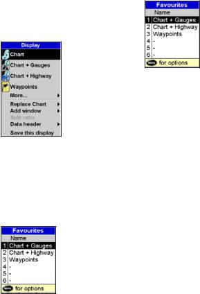
Exchanging two windows on the display
1Press  twice to change the active window.
2Press  , select Replaceand select the second window.
The 5507/5607 exchanges the two windows.
Replacing a window on the display
1Press  twice to change the active window.
2Press  , select Replaceand select a new window that is not currently visible.
Note: When some windows are small then not all the data is shown.
The active window
If there is more than one window displayed, the active window is indicated by a red border. Press  twice to change the active window.
Pressing  will display the options menu for the active window.
Chart is active Red border
Gauges is active Red border
16 |
NAVMAN TRACKER 5507/5607 Installation and Operation Manual |
2-8-2Favoritedisplays
The 5507/5607 has a list of commonly used displays, called favorite displays. There can be up to six favorite displays.
Chart, Gauges, Highway, Fuel, Data, and Tanks windows can be combined in a display. Each of these displays can have a data header (see
section 2-8-3) and a compass (see section 2-8-4).
Selecting a favorite display
Press  and select a favorite from the menu.
Adding a favorite display to the list
1Set up the display with the window or windows you want in the new favorite (see sections 2-8-2 and 2-8-3).
2Press  and select Save this display. The 5507/5607 displays the favorites list.
3Select where in the list to add the new favorite. If you select an existing favorite display then the new favorite will replace the existing favorite in the list.
Deleting a favorite display from the list
1Press  twice then select Favorites.
2Highlight the display to delete, press  and select Delete.
Changing the order of the favorites list
1Press  twice then select Favorites.
2Highlight the display to move, press  and select Move up or Move down.
NAVMAN TRACKER 5507/5607 Installation and Operation Manual |
17 |
2-8-3Dataheader
The displays can show data at the top, called the data header.
When you select a window from the display menu (see section 2-8) the 5507/5607 displays an appropriate data header for the window.
Each favorite display (see section 2-8-2) has its own data header. When you select a favorite display, the 5507/5607 recalls the data header for this favorite.
Setting the data header for a display
1 Press and select Data header.
2To turn the data header on or off: i Select Data.
ii Select  or
or  .
.
3To select the size of the data: i Select Size.
iiSelect the size to display. 4 To change the data displayed:
i Select Data setup.
iiChange a data field:
a Press the cursor keys to highlight the field.
b Press  to display a menu of data items.
c Select a data item that is available on your system or select None to leave the field empty.
iiiRepeat the above step to set the other data fields.
 Tip: If all fields in a line are None then the line will not be displayed and the data header will take less space on the display.
5Press  .
.
 Tip: The data header will change when you select another display. To set a data header that
you can recall later, set the header as part of a favorites display (see below).
Favorites displays and data headers
To set a data header for a favorites display, follow the steps to add a favorite (see section 2-8-2
- Adding a favorite display to the list). In step 1, set the data header for the favorite as described above.
Note: Only the Chart, Gauges, Highway, Fuel, Data, and Tanks windows can have a data header.
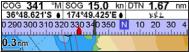
2-8-4Compass
The chart, sonar and highway displays can show a compass at the top of the window.
The compass always shows the boat’s course over ground (COG), a black symbol in the middle. When the boat is navigating to a point, the compass also shows bearing to the destination (BRG), a red symbol.
In this example, BRG is 332°M and COG is 341°M. To turn the compass off or on:
1 Press  and select Data header.
2Set Compass to  or
or  .
.
18 |
NAVMAN TRACKER 5507/5607 Installation and Operation Manual |
3 Navigation: Chart
The chart window shows the chart, the boat’s position course and navigation data.
3-1Overviewofnavigating
The 5507/5607 has two ways of navigating, going straight to a point or following a route.
3-1-1Navigatingtoapoint
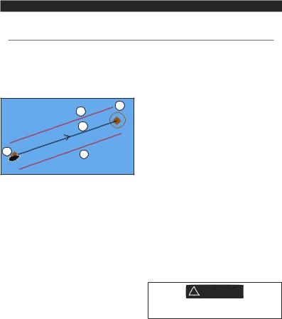
When the 5507/5607 is navigating to a point, the chart and highway windows show navigation data:
B
D
C
AD
AThe boat position .
.
B The destination point marked with a circle.
CThe boat’s plotted course to the destination.
DTwo CDI lines, parallel to the boat’s plotted course, which indicate the maximum expected deviation from the plotted course.
For more information, see appendix C.
If the 5507/5607 is connected to an autopilot, the 5507/5607 will send data to the autopilot to steer the boat to the destination. Start the autopilot before starting to navigate to the point.
If the 5507/5607 has no autopilot, steer the boat manually:
ause the boat position and destination on the chart or highway windows
bor use navigation data window on the data header (see section 2-8-3)
cor use COG and BRG on the compass (see section 2-8-4).
Note:
1If the XTE alarm is enabled, an alarm will sound if the boat deviates too much from its intended course (see section 15-8).
2If the arrival radius alarm is enabled, then an alarm will sound to show that the boat has reached the destination (see section 15-8).
3-1-2Goingtoawaypointortoapointon thechart
A waypoint is a position that you can set on the 5507/5607 chart, for example a fishing spot. (see section 5).
Going to a waypoint from the chart window
1Go to the chart window.
2Move the cursor to the waypoint: either use the cursor keys or use Find (see section 3-2-5).
3Press  and select Goto.
Going to a waypoint from the waypoints window
1Go to the waypoints window.
2Press  or
or  to highlight the waypoint to go to.
3 Press  and select Goto.
Going to a point on the chart
1Switch to a chart window.
2Move the cursor to the destination point: either use the cursor keys or use Find (see section 3-2-5).
3Press  and select Goto cursor.
! WARNING
Make sure the course does not pass over land or dangerous waters.
Navigating
The 5507/5607 navigates to the point as described in section 3-1-1.
Cancelling navigating
Go to a Chart window, press  and select
Cancel goto.
 Tip: Before starting, create waypoints at points of interest. Create a waypoint at the start of the trip for you to navigate back to (see section 5-2-1).
NAVMAN TRACKER 5507/5607 Installation and Operation Manual |
19 |

3-1-3Followingaroute
Preparing
A route is a list of waypoints that the boat can follow (see section 6).
To create waypoints before creating the route, see section 5-2-1.
To create a route, see section 6-2-1.
Starting a route from the chart window:
1Go to the chart window.
2Press  and select Start Route.
3Press  or
or  to highlight the route to follow. Press
  .
.
4The 5507/5607 asks for the direction to traverse the route.
Select Forward (the order the route was created) or Reverse.
5The 5507/5607 displays the chart with the route marked and starts navigating from the start of the route.
Starting a route from the routes window:
1Go to the routes window.
2Press  or
or  to highlight the route to follow. Press
  and select Start.
3The 5507/5607 asks for the direction to traverse the route.
Select Forward (the order the route was created) or Reverse.
4The 5507/5607 displays a chart with the route marked and starts navigating from the start of the route.
Navigating
The 5507/5607 navigates to each waypoint on the route in turn as described in section 3-1-1.
The 5507/5607 stops navigating to the waypoint at the end of the current leg and starts the next leg of the route:
awhen the boat comes within 0.025 nm of the waypoint
b or when the boat passes the waypoint c or if you skip the waypoint.
Skipping a waypoint
To skip a waypoint, go to a chart window, press  and select Skip. The 5507/5607 starts navigating straight towards the next waypoint
on the route.
! WARNING
Skipping a waypoint with the autopilot on might result in a sudden course change.
Cancelling a route
When the boat has reached the final waypoint, or to stop the boat following the route at any time,
cancel the route. Go to a chart window, press  and select Cancel route.
20 |
NAVMAN TRACKER 5507/5607 Installation and Operation Manual |
3-2Chartwindow
To go to the Chart window, press  then select Chart.
A typical chart window shows:
A
B
C
|
F |
|
|
|
|
H |
||||||
|
|
|
|
|||||||||
|
D |
|
|
|
|
|
|
|
|
|
I |
|
|
|
|
|
|
||||||||
|
E |
|
|
|
|
|
|
|
|
|
|
|
|
|
|
|
|
|
|
|
|
J |
|||
|
|
|
|
|||||||||
|
|
|
|
|
|
|
|
|
|
|
||
|
|
|
|
|
|
|
|
|
|
|
|
K |
|
G |
|
||||||||||
|
|
|
||||||||||
|
|
|
|
|
|
|
|
|
|
|
|
|
|
|
|
|
|
|
|
|
|
|
|
|
|
A |
Data header. To turn the data off or on or to change what data is displayed (see section 2-8-2) |
|||||||||||
|
|
|
|
|
|
|
|
|
|
|
|
|
B |
Compass (see section 2-8-3) |
|
|
|||||||||
|
|
|
|
|
|
|
|
|
|
|
|
|
C |
Chart scale (see section 3-2-3) |
|
|
|||||||||
|
|
|
|
|
|
|
|
|
|
|
|
|
D |
Boat position (see section 3-2-1) |
|
|
|||||||||
|
|
|
|
|
|
|
|
|
|
|
|
|
E |
Boat track (see section 3-5) |
|
|
|||||||||
|
|
|
|
|
|
|
|
|
|
|
|
|
F |
Boat course and CDI lines (see Appendix C, CDI) |
|
|
|||||||||
|
|
|
|
|
|
|
|
|
|
|
|
|
G |
Distance and bearing of cursor from boat |
|
|
|||||||||
|
|
|
|
|
|
|
|
|
|
|
|
|
H |
Land |
|
|
|||||||||
|
|
|
|
|
|
|
|
|
|
|
|
|
I |
Sea |
|
|
|||||||||
|
|
|
|
|
|
|
|
|
|
|
|
|
J |
The cursor (see section 3-2-1) |
|
|
|||||||||
|
|
|
|
|
|
|
|
|
|
|
|
|
K |
A typical waypoint (see section 5) |
|
|
|||||||||
|
|
|
|
|
|
|
|
|
|
|
|
|
Note: To change the types of information displayed on the chart (see section 15-2)
NAVMAN TRACKER 5507/5607 Installation and Operation Manual |
21 |
3-2-1Chartmodes
The Chart has two modes: Centre on boat mode
To switch to centre on boat mode in the chart window, press  . The boat
 is at the centre of the chart. As the boat moves through the water, the chart automatically scrolls to keep the boat in the centre of the chart. The cursor (see below) is turned off.
Cursor mode
The keys 

 and
and  are called cursor keys. To switch to cursor mode in the chart window, hold down a cursor key. The cursor
  appears and moves away from the boat:
Press the key which points in the direction that the cursor will move, for example press  to move the cursor down.
Press midway between two of the cursor keys to make the cursor move diagonally.
Hold a cursor key down to make the cursor move continuously across the display.
In Cursor mode:
The distance ( DST) and bearing (
 BRG) of the cursor from the boat are displayed at the bottom, left corner of the display.
The chart does not scroll as the boat moves.
If the cursor reaches the edge of the display, the chart will scroll.
For example, hold down  to move the cursor to the right side of the display and the chart will scroll to the left.
3-2-2Latitudeandlongitude
Latitude and longitude can be displayed in the data header. The display is degrees and minutes to three decimal places, about 2 m (6 ft) resolution. Normally the position is the boat’s position, and the latitude and longitude has a boat symbol to show this:
36° 29.637’ N or S |
Latitude |
175° 09.165’ E or W |
Longitude |
If the cursor has been moved in the last ten seconds, then the position is the cursor’s position, and the latitude and longitude has a cursor symbol to show this:
36° 29.841’ N or S |
Latitude |
175° 09.012’ E or W |
Longitude |
! WARNING
When reading the boat position, make sure the position is not the cursor position.
3-2-3Chartscale
Press  to zoom in and display a smaller area of the chart in more detail. Press
  to zoom out and display a bigger area in less detail.
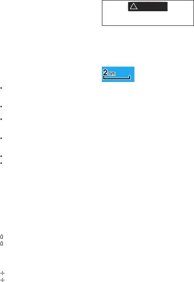
The chart scale is displayed at the top left of the chart:
3-2-4Chartsymbolsandinformation
The chart will show symbols, such as waypoints and chart symbols (for example buoys, beacons, wrecks and marinas). When the cursor is placed over a symbol for at least two seconds, a data window appears at the bottom left of the display with information about the symbol.
To see stored information about a point on the chart (for example, a chart symbol):
1 Move the cursor to that point on the chart. 2 Press  and select Chart info.
3 A menu of objects is displayed:
iSelect an object to display.
iiPress  to return to the menu. Select other objects.
iiiFinally, press  to return to the chart.
3-2-5Findingachartsymbol
To find and display a chart symbol:
1Press  and select Find.
2Select the type of symbol: Waypoints, Routes, Ports by name, Ports & services, Tide stations or AIS Vessels.
3For Ports & services: select the type of service to find.
For Ports by name: press  ,
,  ,
,  or
or  to enter a name or letters contained in the port name, then press
  .
.
4A list of items is displayed. If there are more items than will fit on the display, press  or
or  to page up and down.
22 |
NAVMAN TRACKER 5507/5607 Installation and Operation Manual |
For Ports by name: to search for a different port name, press  . change the name, then press
  .
.
5Select the item and press  . The chart window changes to show the item in the middle of the display.
To see stored information about the item, press  (see section 3-2-4).
3-2-6Perspectiveview
Perspective view shows the chart from an angle instead of from straight above. To turn
perspective view on or off, press  and set
Perspective to  or
or  .
.
3-3Distanceandbearingcalculator
The distance and bearing calculator can plot a course of one or several legs and show the bearing and length of each leg, as well as the total distance along the course. The completed course can be converted into a route.
To use the distance and bearing calculator:
1Press  until the chart window
is displayed. Press  and select
Distance.
2Move the cursor to the start of the first leg. It
does not matter if this point is a waypoint or not. Press  .
.
3To add a leg to the course, move the cursor to the end of the leg. It does not matter if this point is a waypoint or not. The display shows the bearing and length of the leg, as well
as the total distance along the course. Press  .
.
4To remove the last leg from the course, press  and select Remove.
5Repeat the above two steps to enter the whole course.
6To save the new course as a route, press  and select Save. This also saves any new points on the course as new waypoints, with default names. If necessary, edit the route later (see section 6-2-2) and edit any new waypoints later (see section 5-2-3).
7Finally, press  to return to the chart window.
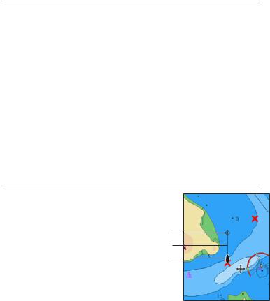
3-4Projectedcourse
If Projected course is turned on, then the 5507/5607 will display the projected position based on the course over ground (COG), speed and a specified time. To turn Projected course on and off and to set the time, see section 15-2.
AProjected position
B Boat’s projected course
CBoat position
A
B
C
NAVMAN TRACKER 5507/5607 Installation and Operation Manual |
23 |

3-5Tracksandtracking
Tracking records the boat’s position to memory at regular intervals, which can be:
Time intervals.
Or distance intervals.
The track of where the boat has been can be displayed on the chart. The 5507/5607 can display one track while recording another.
To work with tracks, see section 15-5. The 5507/5607 can store five tracks:
Track 1 can hold up to 2000 points and is intended to record the normal progress of the boat.
Tracks 2, 3, 4 and 5 can hold up to 500 points each and are intended to record sections to be retraced accurately, for example entering a river mouth.
 Tip: Record the tracks in good conditions.
When recording is on and the track becomes full then recording continues and the oldest points in the track are deleted. The maximum length of a track depends on the selected track interval: a small interval will give a shorter, more detailed track and a long interval will give a longer, less detailed track, as shown in these examples:
The track lengths are in the current distance units, for example nm.
Time intervals
Interval |
Track 1 |
Track 2, 3, 4 |
|
|
or 5 |
|
|
|
1 sec |
33 minutes |
8 minutes |
|
|
|
10 sec |
5.5 hours |
1.4 hours |
|
|
|
1 min |
33 hours |
8 hours |
|
|
|
Distance intervals |
|
|
|
|
|
Interval |
Track 1 |
Track 2, 3, 4 |
|
|
or 5 |
|
|
|
0.01 |
20 |
5 |
|
|
|
1 |
2,000 |
500 |
|
|
|
10 |
20,000 |
5,000 |
|
|
|
24 |
NAVMAN TRACKER 5507/5607 Installation and Operation Manual |
 Loading...