


IN-HULL

NAVMAN
www.navman.com
Installation Manual
THROUGH HULL AND
IN-HULL TRANSDUCERS
English..............3
Français.......... 10
Español...........18
Português....... 26

2 Through hull & In-hull transducer installation manual
NAVMAN
FCC Statement
Note: This equipment has been tested and found to comply with the limits for a Class
B digital device, pursuant to Part 15 of the FCC Rules. These limits are designed to
provide reasonable protection against harmful interference in a normal installation.
This equipment generates, uses and can radiate radio frequency energy and, if not
installed and used in accordance with the instructions, may cause harmful interference
to radio communications. However, there is no guarantee that interference will not
occur in a particular installation. If this equipment does cause harmful interference to
radio or television reception, which can be determined by turning the equipment off
and on, the user is encouraged to try to correct the interference by one or more of the
following measures:
Reorient or relocate the receiving antenna
Increase the separation between the equipment and receiver
Connect the equipment into an output on a circuit different from that to which the
receiver is connected
Consult the dealer or an experienced technician for help
A shielded cable must be used when connecting a peripheral to the serial ports.
Important
It is the owner’s sole responsibility to install and use Navman’s transducers in a manner that
will not cause accidents, personal injury or property damage. The user of this product is solely
responsible for observing safe boating practices.
Transducer installation: The choice, location, angle and installation of the transducer is the most
critical part of installation. If installation is not correct, the unit can not perform at its designed
potential. If in doubt, consult your Navman dealer. Ensure that any holes that cut are in a safe
position and will not weaken the boat’s structure. If in doubt, consult a qualifi ed boat builder.
Disclaimer: The information in this manual is provided as a guide only. The transducer’s
performance is infl uenced by the boat’s material, hull design and engine installation and these
are beyond the control of Navman NZ Limited.
NAVMAN NZ LIMITED DISCLAIMS ALL LIABILITY FOR ANY USE OF THIS PRODUCT IN A
WAY THAT MAY CAUSE ACCIDENTS, DAMAGE OR THAT MAY VIOLATE THE LAW.
Governing language: This statement, any instruction manuals, user guides and other information
relating to the product (Documentation) may be translated to, or has been translated from,
another language (Translation). In the event of any confl ict between any Translation of the
Documentation, the English language version of the Documentation will be the offi cial version
of the Documentation.
This manual represents the transducer installation procedures as at the time of printing. Navman
NZ Limited reserves the right to make changes to specifi cations without notice.
Copyright © 2003 Navman NZ Limited, New Zealand, all rights reserved. Navman is a registered
trademark of Navman NZ Limited.

3Through hull & In-hull transducer installation manual
NAVMAN
1-1 Wiring
Each transducer has a cable to connect it to the
navigation instrument. When fi tting this cable:
Keep the cable away from other cables
and equipment (for example fl uorescent
lights, power inverters and VHF
transmitters.)
Do not cut the cable on any depth
transducer
If necessary, extend the cable by adding
a Navman 4 m (13 ft) extension cable (a
1 Introduction
1-2 Cleaning and maintenance
Clean a transducer with a damp cloth or mild
detergent. Avoid abrasive cleaners and petrol
or other solvents.
When repainting the hull, cover or remove any
speed transducers. Do not paint the transducer.
This manual describes how to install:
Navman’s range of through hull depth and
speed/temperature transducers
Navman’s in-hull depth transducer.
Accessories
These accessories are available from your
Navman dealer:
4 m (13 ft) speed/temperature transducer
extension cable
4 m (13 ft) depth transducer extension
cable for both single and dual frequency
units
Replacement speed/temperature
transducer hull fi tting
Replacement speed/temperature
transducer paddlewheel
20 m (65 ft) dual frequency depth
transducer extension cable.
maximum of one cable can be used). For
dual frequency transducers, a 20 m (65 ft)
extension cable is available.
Ensure no cable connectors lie
in the bilge
Secure the cable at regular intervals
Refer to the navigation instrument’s
installation manual for instructions on how
to connect the cable to the instrument.
Do not use a high pressure water blast on
the speed transducer paddlewheel as it may
damage the bearings.
Contents
1 Introduction.............................................................................................3
1-2 Cleaning and maintenance ............................................................................ 3
1-1 Wiring ............................................................................................................. 3
2 Through hull transducers......................................................................4
2-1 Positioning a through hull transducer............................................................. 6
2-2 Installing a through hull transducer ................................................................ 6
3 In-hull depth transducer ........................................................................8
3-1 Positioning an in-hull transducer.................................................................... 8
3-2 Installing an in-hull depth transducer ............................................................. 9
4 Through hull & In-hull transducer installation manual
NAVMAN
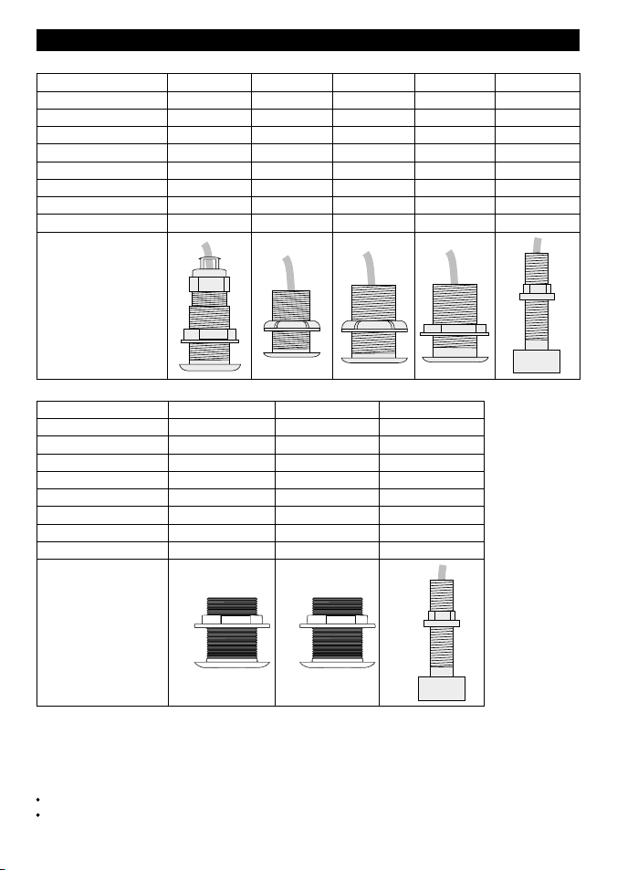
Part # - Europe 47535 47512 Not available
Part # - Rest of World AA002108 AA002107 AA002109
Material Bronze Plastic Bronze
Type (1) Fixed (Dual freq.) Fixed (Dual freq.) Fixed (Dual freq.)
Connector 6-pin LT 6-pin LT 6-pin LT
Hull hole diam. 2½" (63.5 mm) 2½" (63.5 mm) 1
1
/
6
" (27 mm)
Max. hull thickness 3
1
/
8
" (80 mm) 2¼" (56 mm) 4
7
/
8
" (110 mm)
Cable length 33 ft (10 m) 33 ft (10 m) 33 ft (10 m)
Flush or long stem Flush Flush Long stem
2 Through hull transducers
Depth transducers:
Part # - Europe 25983 26032 31357 31358 Not available
Part # - Rest of World Not available AA002155 Not available AA002106 AA000043
Material Plastic Plastic Plastic Bronze Bronze
Type (1) Insertable Fixed Fixed Fixed Fixed
Connector RCA phono RCA phono RCA phono RCA phono RCA phono
Hull hole diam. 1
7
/
8
" (48 mm) 1
5
/
8
" (42 mm) 2" (51 mm) 2" (51 mm)
7
/
8
" (22 mm)
Max. hull thickness 2
3
/
8
" (60 mm) 1
5
/
8
" (42 mm)
7
/
8
" (22 mm) 2
3
/
8
" (60 mm) 2
5
/
8
" (92 mm)
Cable length 26.2 ft (8 m) 26.2 ft (8 m) 26.2 ft (8 m) 26.2 ft (8 m) 29.5 ft (9 m)
Flush or long stem Flush Flush Flush Flush Long stem
Notes
1 With an insertable transducer, the transducer element can be removed, leaving the hull
fi tting in place in the hull. With a fi xed transducer, the transducer element and hull fi tting can
not be separated.
Caution
Plastic through hull transducers are not suitable for wooden hulls.
Bronze transducers are usually unsuitable for metal hulls.
5Through hull & In-hull transducer installation manual
NAVMAN
Speed/temperature transducers:
Part # - Europe 25982 40640 26017 40641
Part # - Rest of
World
Not available Not available AA002150 AA002082
Material Plastic Plastic Plastic Bronze
Type (1) Insertable Insertable Insertable Insertable
Connector 4-pin Fuji 8-pin LT 4-pin Fuji 8-pin LT
Hull hole diam. 1
7
/
8
" (48 mm) 1
7
/
8
" (48 mm) 1
5
/
8
" (42 mm) 1
5
/
8
" (42 mm)
Max. hull thickness 2
3
/
8
" (60 mm) 2
3
/
8
" (60 mm) 1
5
/
8
" (42 mm) 1
5
/
8
" (42 mm)
Cable length 26.2 ft (8 m) 26.2 ft (8 m) 26.2 ft (8 m) 26.2 ft (8 m)
Flush or long stem Flush Flush Flush Flush
Same as
25982, but
with 8-pin LT
connector
Same as
AA002150 /
26017, but
with 8-pin LT
connector
Part # - Europe 31359 47552
Part # - Rest of
World
AA000055 AA002151
Material Bronze Bronze
Type (1) Insertable Insertable
Connector 4-pin Fuji 8-pin LT
Hull hole diam. 2" (51 mm) 2" (51 mm)
Max. hull thickness 2
1
/
8
" (55 mm) 2
1
/
8
" (55 mm)
Cable length 29.5 ft (9 m) 29.5 ft (9 m)
Flush or long stem Flush Flush
Same as
AA000055 /
31359, but
with 8-pin LT
connector
Notes
1 With an insertable transducer, the transducer element can be removed, leaving the hull
fi tting in place in the hull. With a fi xed transducer, the transducer element and hull fi tting
can not be separated.
Caution
Plastic through hull transducers are not suitable for wooden hulls.
Bronze transducers are usually unsuitable for metal hulls.
6 Through hull & In-hull transducer installation manual
NAVMAN
2-2 Installing a through hull transducer
1 Select a suitable position for the
transducer (see section 2-1).
If the hull panel is too thin or the panel
might not be strong enough, consider
fi tting a reinforcing pad on the inside of
the hull.
2 Find the hole size required for the
transducer from the table above. Drill or
cut the hole in the hull. The hole must be
perpendicular to the hull surface.
3 For an insertable transducer:
i remove the locking nut or pin
rom the fi tting
ii pull the transducer out from the
hull fi tting
iii unscrew the nut from the hull fi tting.
For a fi xed transducer:
i unscrew the nut from the hull fi tting
ii hold the nut just inside the hole
in the hull
iii feed most of the transducer cable
through the hole in the hull (from the
outside) and through the nut.
4 Apply a thick layer of fl exible bedding
compound (such as Sikafl ex) to the
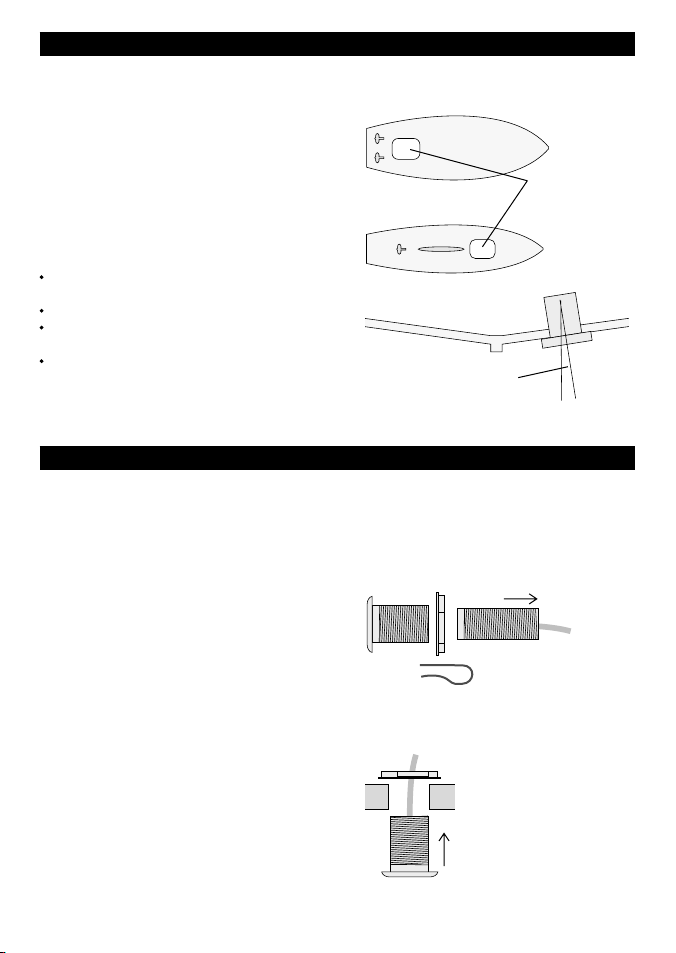
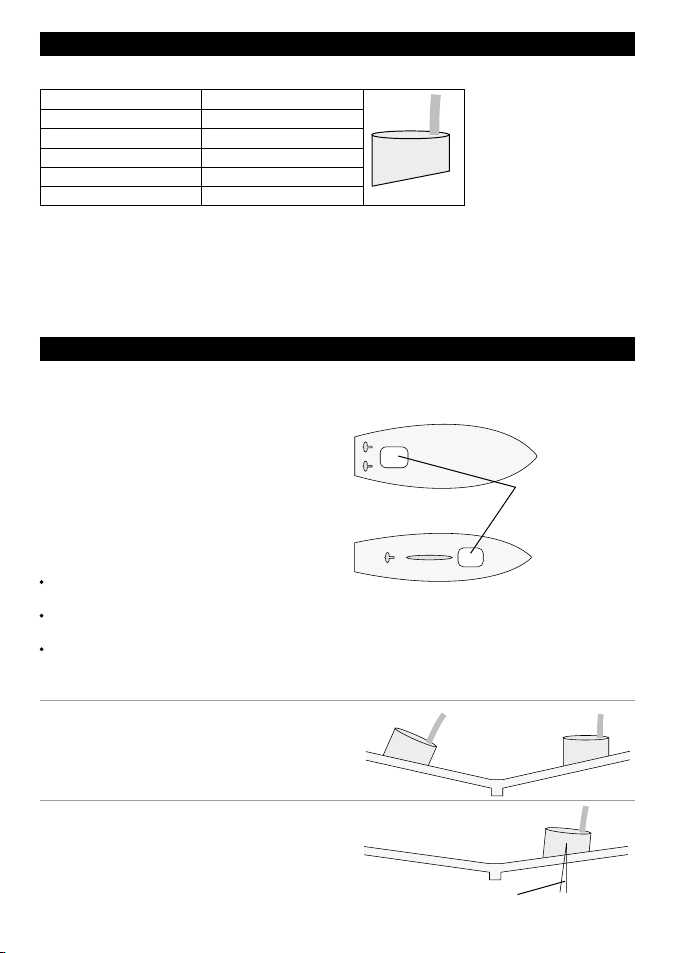
2-1 Positioning a through hull transducer
This transducer will be fi tted in a hole drilled
in the bottom of the boat. Select a position
for the transducer that has a smooth fl ow of
clear water over the transducer surface at all
times. This means that the transducer should
be ahead of any keel, hull projections, hull
openings, paddle wheel transducers, propellers
or propeller wash. If the bottom of the boat is
painted and the boat has been used, do not
mount the transducer where the paint is eroded
(an indication of turbulence).
In addition, position the transducer:
as close to the middle line of the hull as
possible and as deep as possible
where the deadrise angle is small
with suffi cient space inside the hull for
access and wiring
so that it will not interfere with launching
or retrieving the boat
Ideally a depth transducer should be fi tted so
that its axis is vertical, however it can be up to
15° off vertical.
Planing or displacement boat
Sailing boat
Suitable
locations for
transducer
Remove
transducer
Insertable transducer
Fixed transducer
Remove locking
nut or pin
Up to 15°
7Through hull & In-hull transducer installation manual
NAVMAN
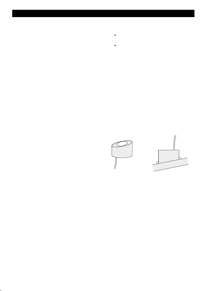
Bedding
compound
Arrow faces forward
to within 5°
Arrow
5°
hull fi tting on the inside face of the fl ange
and on the exterior threads where they
pass through the hull.
5 Insert the hull fi tting into the hull from
outside. For a speed/temperature
transducer, rotate the fi tting until the arrow
on the outside lip points forward to within 5°.
6 Fit and tighten the nut on the hull fi tting.
For a plastic fi tting, hand-tighten the nut
and do not over tighten. For a bronze
fi tting, tighten with slip-joint pliers.
Tighten the nut until excess bedding
compound is squeezed out from under
the nut and the face of the hull fi tting.
Remove the excess bedding compound.
7 For a speed/temperature transducer,
check that the arrow on the hull fi tting still
points forward.
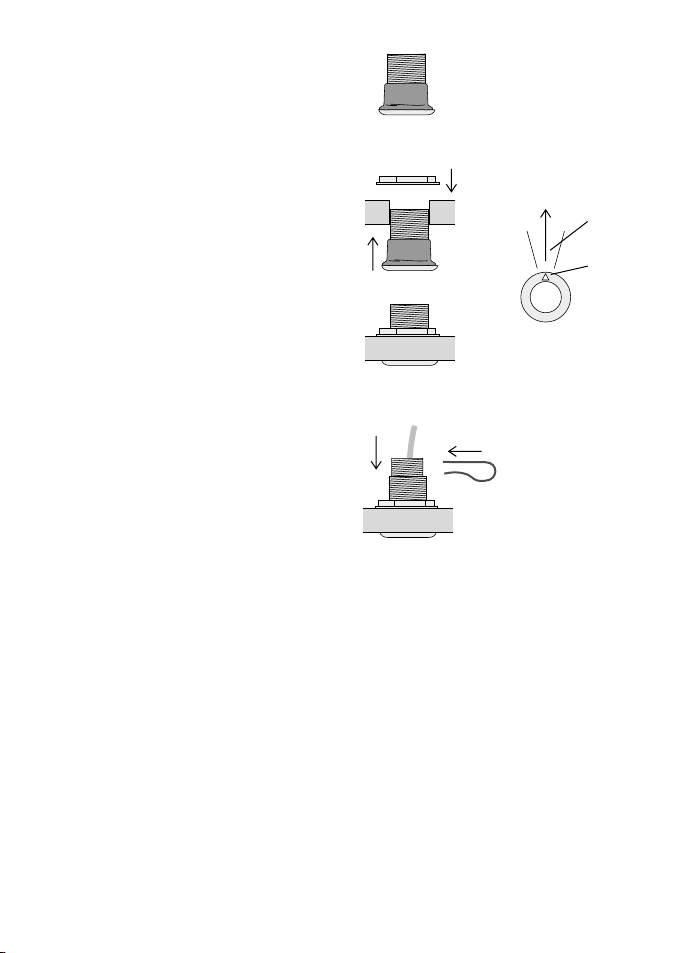
8 For an insertable transducer:
i ensure there is a thin layer of silicone
grease or O-ring lubricant on the
transducer O-rings
ii insert the transducer back into the hull
fi tting, rotating the transducer so that
the arrow on the transducer mates
with the notch on the fi tting
iii replace the locking nut or pin.
9 Wait for the bedding compound to dry.
10 Before leaving the boat unattended,
check that there is no water ingress
from around the transducer.
Grease
Insert
Replace locking nut or pin
Forward
View from bottom
Insertable transducer
8 Through hull & In-hull transducer installation manual
NAVMAN
3 In-hull depth transducer
3-1 Positioning an in-hull transducer
This transducer will be glued to the inside of
the bottom of the boat. Select a position for the
transducer that has a smooth fl ow of clear water
under the transducer at all times. This means
that the transducer should be ahead of any keel,
hull projections, hull openings, paddle wheel
transducers, propellers or propeller wash. If
the bottom of the boat is painted and the boat
has been used, do not mount the transducer
where the paint is eroded (an indication of
turbulence).
In addition, position the transducer:
as close to the middle line of the hull as
possible and as deep as possible
with suffi cient space inside the hull for
access and wiring
where the inside surface of the hull is fl at and
smooth and there will be no gaps between
the face of the transducer and the hull.
Planing or displacement boat
Sailing boat
Suitable locations
for transducer
Up to 15°
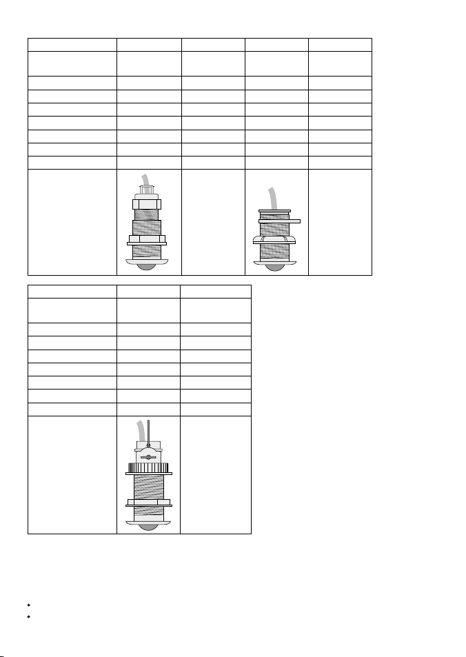
Part # - Europe 27948
Part # - Rest of World AA002161
Material Plastic
Connector RCA phono
Max. hull thickness ¾" (20 mm)
Cable length 26.2 ft (8 m)
One in-hull transducer is available, a depth transducer.
Caution
In-hull depth transducers are only suitable for solid GRP hulls up to ¾" (20 mm) thick, without air
pockets, beads or voids. They are not suitable for wooden, metal or sandwich hulls. Compared to
other types of transducer, in-hull depth transducers generally have lower performance because
power is absorbed in the hull.
No Yes
Ideally the transducer should be rotated so
that its axis is vertical, however it can be up
to 15° off vertical.
The face of the transducer is angled. When
fi tting the transducer, rotate the transducer so
that the axis of the transducer is as close to
vertical as possible.
9Through hull & In-hull transducer installation manual
NAVMAN
1 Select a suitable position for the
transducer and establish how the
transducer should be rotated so that the
axis is as vertical as possible (see section
2-1).
2 Test the transducer at this position
with the boat in the water before
mounting it permanently:
i Partially fi ll a thin plastic bag with
water, place the transducer inside and
close it tightly around the cable
with a tie-wrap.
ii Install the depth instrument as
described in the instrument’s
Installation and Operation manual.
iii Wet the surface of the hull and press
the transducer against the inside of
the hull where you plan to mount the
transducer.
iv Check that the instrument measures
depth correctly and consistently, up
to the maximum depth specifi ed for
the instrument. If necessary, move the
bag around the hull to fi nd the best
position.
3 Choose an adhesive or sealant to glue
the transducer to the hull. Hard epoxies
transmit the transducer signals best but
temperature changes and hull fl exing can
cause delamination. As a compromise,
use a viscous slow cure, fairly rigid epoxy
or Sikafl ex 252 sealant.
3-2 Installing an in-hull depth transducer
4 Ensure the inside of the hull where the
transducer will be mounted is fl at.
Clean, degrease and dry:
the inside of the hull where the
transducer will be mounted
the sloping face of the transducer
5 Fit the transducer:
i Apply the epoxy or sealant to the
middle of the transducer face.
ii Press the transducer into place
on the hull.
iii Twist the transducer back and forth to
expel any trapped air and to expel as
much glue as possible from the joint.
The fi nished joint should be as thin as
possible and not contain any
air bubbles.
Leave the transducer rotated to the
correct angle.
iv Temporarily secure the transducer in
place with tape and wait for the glue
to cure for 24 hours.
Glue

10 Guide d’installation des capteurs traversants et des
sondes à montage interne
NAVMAN
Important
Il incombe au propriétaire de veiller à ce que l’instrument et le capteur soient installés et utilisés
de telle sorte qu’ils ne causent pas d’accidents, de blessures ou de dommages matériels.
L’utilisateur de ce produit est seul responsable du respect des règles de sécurité en matière
de navigation.
Installation du capteur : une attention toute particulière doit être portée au choix, à
l’emplacement et à l’angle de montage du capteur. Si le capteur n’est pas correctement installé,
il ne pourra pas fonctionner de manière optimale. N’hésitez pas à consulter votre revendeur
Navman pour des informations complémentaires. Veillez à ce que les trous de montage soient
percés à des endroits adaptés et n’endommagent pas la structure du bateau. En cas de doute,
veuillez vous adresser à un chantier naval.
Avertissement : les informations contenues dans cette notice sont données à titre indicatif.
Certains facteurs indépendants de la volonté de Navman NZ Limited, tels que le matériau de
construction du bateau, la forme de la coque ou l’installation moteur, ont une infl uence sur les
performances du capteur.
NAVMAN NZ LIMITED DECLINE TOUTE RESPONSABILITE DANS LE CAS D’UNE
UTILISATION DU PRODUIT OCCASIONNANT DES ACCIDENTS, DES DOMMAGES MATE-
RIELS OU UN NON-RESPECT DE LA LOI.
Langue de référence : cette notice a été traduite de l’anglais. En cas de litige concernant
l’interprétation de la notice, la version anglaise de la notice prévaudra.
Cette notice présente les procédures d’installation des capteurs traversants et des sondes à
montage interne telles qu’elles sont à la date d’impression. Navman NZ Limited se réserve le
droit de modifi er les spécifi cations contenues dans cette notice sans préavis.
Copyright © 2003 Navman NZ Limited, Nouvelle-Zélande. Tous droits réservés. NAVMAN est
une marque déposée de Navman NZ Limited.

11Guide d’installation des capteurs traversants et des
sondes à montage interne
NAVMAN
1-1 Câblage
Chaque capteur est équipé d’un câble qui doit
être relié à l’instrument de navigation. Lors de
l’installation :
S’assurer que le câble passe le plus loin
possible des autres câbles et du reste de
l’équipement (lampes fl uo, convertisseurs
et émetteurs-récepteurs VHF).
Ne pas couper le câble d’une sonde.
Si nécessaire, utiliser un câble
d’extension 4 m (une seule rallonge
possible). Un câble d’extension 20 m est
1 Introduction
1-2 Nettoyage et entretien
Nettoyer le capteur à l’aide d’un chiffon humide
ou imprégné de détergent doux. Ne pas utiliser
de produits abrasifs, d’essence ou tout autre
solvant.
Si vous désirez repeindre la coque, recouvrir
ou retirer tout capteur de vitesse présent. Ne
pas peindre le capteur.
Ce guide explique comment installer :
les capteurs traversants Navman (vitesse/
température et profondeur).
la sonde à montage interne Navman.
Accessoires
Les accessoires suivants sont disponibles
chez votre revendeur local :
Câble d’extension 4 m pour capteur de
vitesse/température.
Câble d’extension 4 m pour sonde mono
ou bi-fréquence.
Passe-coque de rechange pour capteur
de vitesse/température.
Roue à aubes de rechange pour capteur
de vitesse/température.
Câble d’extension 20 m pour sonde bi-
fréquence.
également disponible pour les sondes
bi-fréquence.
S’assurer qu’aucun connecteur de câble
ne repose sur le fond de cale.
Attacher le câble à intervalles réguliers.
Pour la connexion du câble à l’instrument,
se référer au guide d’installation de
l’instrument de navigation.
Ne jamais utiliser de système de nettoyage
haute pression sur la roue à aubes du capteur
de vitesse afi n de ne pas endommager les
paliers.
Sommaire
1 Introduction.............................................................................................3
1-1 Câblage.......................................................................................................... 3
1-2 Nettoyage et entretien.................................................................................... 3
2 Capteurs traversants .............................................................................4
2-1 Choix de l’emplacement d’un capteur traversant........................................... 6
2-2 Installation d’un capteur traversant ................................................................ 6
3 Sonde à montage interne.......................................................................8
3-1 Choix de l’emplacement d’une sonde à montage interne .............................. 8
3-2 Installation d’une sonde à montage interne ................................................... 9
 Loading...