


MULTI 3100
Installation and
Operation Manual
DRAFT
Approved by translator |
English ............. |
2 |
|
Français ......... |
18 |
Approved by Plastimo |
|
|
|
Español .......... |
33 |
This document is still under review and is subject to change. |
Português ...... |
48 |
Each completed stage to be marked with |
|
|
w w w . n a v m a n . c o m
NAVMAN MULTI 3100 Installation and Operation Manual
NAVMAN
1

FCC Statement
Note: This equipment has been tested and found to comply with the limits for a Class B digital device, pursuant to Part 15 of the FCC Rules. These limits are designed to provide reasonable protection against harmful interference in a normal installation. This equipment generates, uses and can radiate radio frequency energy and, if not installed and used in accordance with the instructions, may cause harmful interference to radio communications. However, there is no guarantee that interference will not occur in a particular installation. If this equipment does cause harmful interference to radio or television reception, which can be determined by turning the equipment off and on, the user is encouraged to try to correct the interference by one or more of the following measures:
Reorient or relocate the receiving antenna.
Increase the separation between the equipment and receiver.
Connect the equipment into an output on a circuit different from that to which the receiver is connected.
Consult the dealer or an experienced technician for help.
A shielded cable must be used when connecting a peripheral to the serial ports.
2 |
NAVMAN |
MULTI 3100 Installation and Operation Manual |

Contents |
|
1 Introduction ..................................................................................................... |
5 |
2 Operation ......................................................................................................... |
6 |
2-1 Turn on and off ............................................................................................................ |
6 |
2-2 Basic operation ............................................................................................................ |
6 |
2-3 Change units ............................................................................................................... |
6 |
2-4 Alarms ......................................................................................................................... |
6 |
2-5 Simulate mode ............................................................................................................. |
6 |
2-6 Key reference .............................................................................................................. |
7 |
3 Speed, average speed, maximum speed, trim speed .................................. |
8 |
3-1 Set speed and log units ............................................................................................... |
8 |
3-2 Reset average speed ................................................................................................... |
8 |
3-3 Reset maximum speed ................................................................................................ |
8 |
3-4 Reset trim speed ......................................................................................................... |
8 |
3-5 Set speed damping ...................................................................................................... |
8 |
3-6 Set speed resolution .................................................................................................... |
8 |
3-7 Calibrate speed ........................................................................................................... |
8 |
4 Log and total log ............................................................................................. |
9 |
4-1 Reset log ..................................................................................................................... |
9 |
4-2 Reset total log .............................................................................................................. |
9 |
5 Depth, keel offset, too deep alarm, too shallow alarm ............................... |
10 |
5-1 Set depth units .......................................................................................................... |
10 |
5-2 Set too deep alarm ..................................................................................................... |
10 |
5-3 Set too shallow alarm ................................................................................................. |
10 |
5-4 Anchor watch ............................................................................................................. |
10 |
5-5 Set keel offset ............................................................................................................ |
10 |
6 Temperature .................................................................................................... |
11 |
6-1 Set temperature units ................................................................................................ |
11 |
6-2 Calibrate temperature ................................................................................................ |
11 |
7 Countdown timer ............................................................................................ |
11 |
7-1 Start countdown timer ................................................................................................ |
11 |
7-2 Stop and reset countdown timer ................................................................................. |
11 |
7-3 Adjust start time ......................................................................................................... |
11 |
8 Systems of several instruments .................................................................. |
12 |
8-1 NMEA ....................................................................................................................... |
12 |
8-2 NavBus ..................................................................................................................... |
12 |
9 MULTI 3100 hardware .................................................................................... |
12 |
9-1 What comes with your MULTI 3100 ........................................................................... |
12 |
9-2 Other parts required .................................................................................................. |
12 |
9-3 Transducers .............................................................................................................. |
13 |
9-4 Accessories ............................................................................................................... |
13 |
NAVMAN MULTI 3100 Installation and Operation Manual |
3 |

10 Installation and setup .................................................................................. |
13 |
10-1 Installation ............................................................................................................... |
13 |
10-2 Setup ....................................................................................................................... |
15 |
10-3 Resetting to factory defaults .................................................................................... |
15 |
Appendix A - Specifications ............................................................................ |
15 |
Appendix B - Troubleshooting ........................................................................ |
16 |
Appendix C - How to contact us ..................................................................... |
63 |
Units
This unit is set up with default units of metres, °C, knots and nautical miles.
Please refer to section 2-3 of this manual to change the units.
Important
It is the owner’s sole responsibility to install and use the instrument and transducer/s in a manner that will not cause accidents, personal injury or property damage. The user of this product is solely responsible for observing safe boating practices.
NAVMAN NZ LIMITED DISCLAIMS ALL LIABILITY FOR ANY USE OF THIS PRODUCT IN A WAY THAT MAY CAUSE ACCIDENTS, DAMAGE OR THAT MAY VIOLATE THE LAW.
This manual represents the MULTI 3100 as at the time of printing. Navman NZ Limited reserves the right to make changes to specifications without notice.
Governing Language: This statement, any instruction manuals, user guides and other information relating to the product (Documentation) may be translated to, or has been translated from, another language (Translation). In the event of any conflict between any Translation of the Documentation, the English language version of the Documentation will be the official version of the Documentation.
Copyright © 2002 Navman NZ Limited, New Zealand. All rights reserved. NAVMAN is a registered trademark of Navman NZ Limited.
4 |
NAVMAN |
MULTI 3100 Installation and Operation Manual |
1 Introduction
The MULTI 3100 measures and displays speed, water depth and water temperature. It can calculate and display average speed, maximum speed, trim speed, trip log (distance) and total log.
An installed MULTI 3100 usually has two parts:
The display unit.
Depth and speed / temperature transducers which are attached to the hull and wired to the display unit.
The unit is powered from the boat’s power supply.
The MULTI 3100 is part of the NAVMAN family of instruments for boats, which includes instruments for speed, depth, wind and repeaters. These instruments can be connected together to form an integrated data system for a boat (see section 8).
For maximum benefit, please read this manual carefully before installation and use.
How the transducer measures depth
The depth transducer generates an ultrasonic (sound) pulse, which travels down through the water. When the pulse meets the bottom, some of the pulse is reflected back up towards the boat and is received by the transducer.
The display unit analyses the reflections from each pulse. It removes unwanted reflections (from bubbles and other objects) and calculates the depth by measuring the time between sending the pulse and receiving its echo.
How the transducer measures speed
The speed transducer has a small paddlewheel which spins as the boat moves through the water. The transducer measures how fast the paddlewheel is spinning and calculates the boat speed by averaging several measurements.
Cleaning and maintenance
Clean the display unit and any plastic transducers with a damp cloth or mild detergent. Avoid abrasive cleaners, petrol or other solvents.
When repainting the hull, cover or remove any visible transducers. Depth transducers may be coated with a thin layer of antifouling paint; gently sand off any previous paint first.
Do not use a high pressure water blast on the speed transducer paddlewheel as it may damage the bearings.
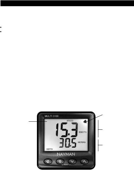
The MULTI 3100 display unit
Alarm symbol
Display (backlit)
Top part of display, (showing boat speed)
Bottom part of display, (showing water depth)
Four keys |
|
111 x 111 mm |
|
||
(backlit) |
|
(4.4" x 4.4") |
NAVMAN MULTI 3100 Installation and Operation Manual |
5 |
2 Operation
2-1 Turn on and off
Turn the unit on and off with the auxiliary power switch on the boat. The unit does not have its own power switch. When you turn it off, any settings you have made are retained.
If the word SIM flashes at the bottom, right of the display, then the unit is in simulate mode (see section 2-5).
2-2 Basic operation
The keys
The unit has four keys, labelled 

 and
and  . In this manual:
Press means to push the key for less than one second.
Hold for two seconds means to hold the key down for two seconds or more.
Press one key + another key means to push both keys together.
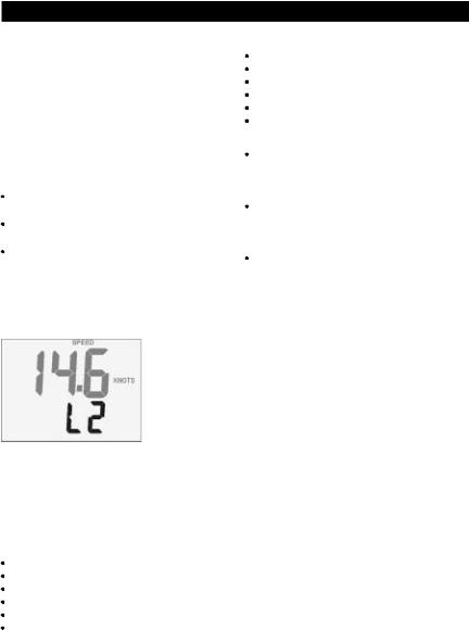
Set backlight level for screen and keys
You can set the backlight to one of four brightness levels or off. Press  once to display the current backlight level, press
  again to change the level:
Backlight
Level 2
Change the items displayed
The display can show two values at once, one in the top part of the screen and one in the bottom. If an item displays as dashes (— —) then it means that the value is outside the range, for example the depth might be too deep or unknown.
To change what is displayed in the top part of the screen, press  one or more times to select:
Speed.
Avg speed.
Max speed.
Trim speed.
Depth.
Temperature.
To change the value displayed in the bottom part of the screen, press  one or more times to select:
Speed.
Depth.
Trip log (distance).
Total log (distance).
Battery voltage. Countdown timer.
2-3 Change units
To change the speed and log units, press  until SPEED is displayed, then hold
  until the units change; if necessary, hold
  again until the units change again.
To change the depth units, press  until DEPTH is displayed, then hold
  until the units change; if necessary, hold
  until the units change again.
To change the temperature units, press  until the temperature is displayed, then hold
  until the units change.
2-4 Alarms
The MULTI 3100 can be set to sound an alarm when the water is too deep or too shallow (see sections 5-2 and 5-3). When the alarm sounds, the internal beeper sounds, the  symbol on the display flashes and any external beepers or lights operate.
Press  to mute the alarm. The alarm stays muted until the depth becomes returns to the pre-alarm condition or is within the alarm parameters. The alarm will sound if the depth becomes too deep or too shallow again.
2-5 Simulate mode
Simulate mode allows you to become familiar with the unit off the water. In Simulate mode, the MULTI 3100 functions normally except that the transducers are ignored and the unit generates this data internally. The word SIMULATE flashes at the bottom, right corner of the screen.
To turn Simulate mode on or off:
1Turn the power off.
2Hold down  while you turn the power on.
6 |
NAVMAN |
MULTI 3100 Installation and Operation Manual |
 Loading...