


L 53
Technical Bulletin
L53
Date:
Note:
Previous T.B.’s required:
DESCRIPTION: In SRS mode when playing certain CD’s and some DVD’S distortion can
be heard coming from the speakers.
REASON: The input level to the SRS decoder chip is to high.
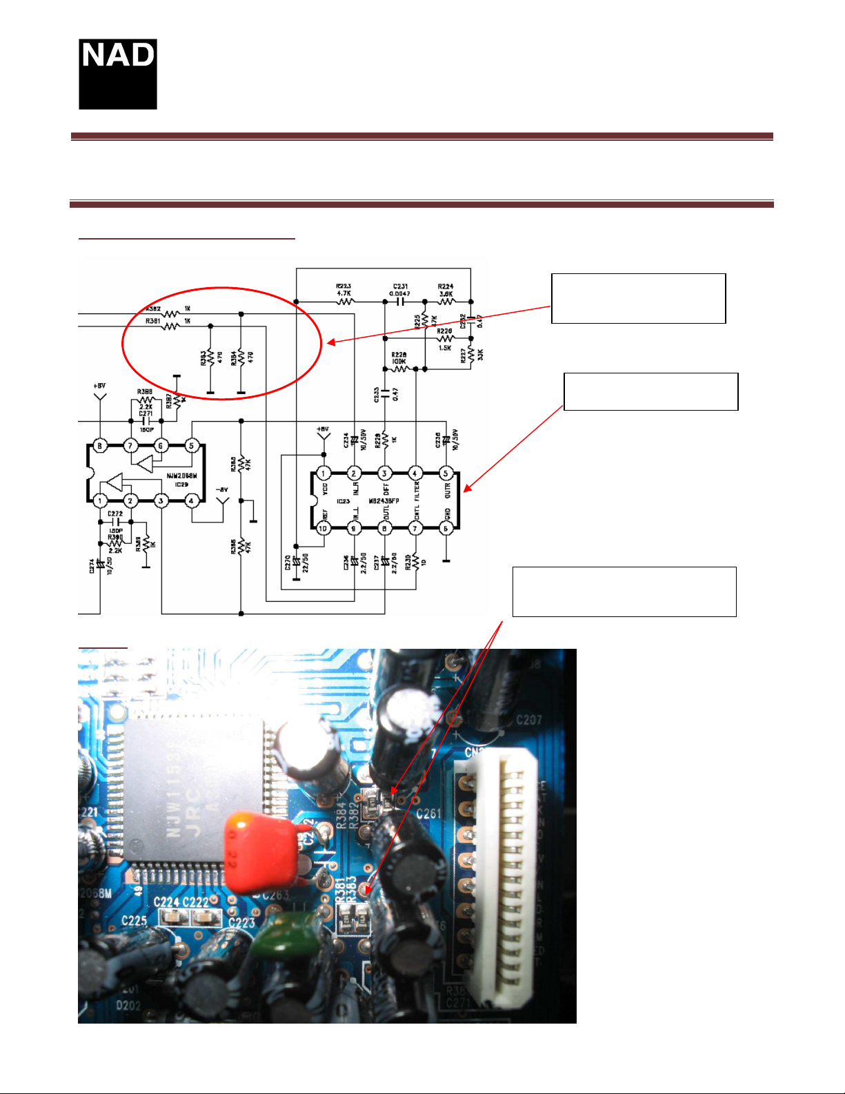
SOLUTION: In figure 1 the red circle is the part of the circuit to change. R383 and R384
are 470 ohms. By lowering these resistor values , distortion in SRS mode will be corrected.
Start by removing the top cover and locate the Audio pc board.This is the upper pc
board mount behind the dvd mechanism.
On the component side of the Audio board locate surface mount chip resistors
R381 and R382. Check that their value is 1k ohm each. See figure 1 and figure 2.
On the Audio board disconnect the tuner module flex cable CN22(see figure 3.)
Main board flex cable (CN24), SPDIF harness (CN33) , and connector board (BN25/26).
Remove the 6 screws from the back panel securing the Audio board.
The resistors that require lowering are R383 and R384 , 470 ohms each. The
addition of another 470 ohm resistor in parallel with each resistor will give an overall
resistance of 235 ohms each.. To do this lift the board and turn over to access the foil side .
Mount the two resistors (470 ohm 1/6w) from the negative side of C234 and C236. to ground
at pin-1 on BN23. See figure 4 .
NOTE: To enjoy SRS on this player we recommend that SRS mode is used with
source material that is surround encoded. Certain stereo material will give unpredictable
results.
Contact:
NAD Electronics International
633 Granite Court
Pickering, ON Canada L1K 3K1
Voice: 905-831-0799 FAX 905-837-6357
www.nadelectronics.com
June 27/05 Subject: SRS Distortion
❑❑❑❑
❑❑❑❑
Product: DVD Receiver
Hardware Technical Bulletin: L53-H2005-01
YES
NO
Page 1 of 3
Technical Bulletin
L53
Figure 1 (schematic of Audio board)
Product: DVD Receiver
Hardware Technical Bulletin: L53-H2005-01
R381,R382,R383,R384
SRS Decoder chip
Figure 2
PC Board top view showing
R381-R384 on Audio board.
Page 2 of 3
 Loading...