


 Loading...

 ® M32
® M32
DirectDigital DAC Amplifier
ENGLISH
Owner’s Manual
ENGLISH
IMPORTANT SAFETY INSTRUCTIONS
1.Read instructions - All the safety and operating instructions should be read before the product is operated.
2.Retain instructions - The safety and operating instructions should be retained for future reference.
3.Heed Warnings - All warnings on the product and in the operating instructions should be adhered to.
4.Follow Instructions - All operating and use instructions should be followed.
5.Cleaning - Unplug this product from the wall outlet before cleaning. Do not use liquid cleaners or aerosol cleaners. Use a damp cloth for cleaning.
6.Attachments - Do not use attachments not recommended by the product manufacturer as they may cause hazards.
7.Water and Moisture - Do not use this product near water-for example, near a bath tub, wash bowl, kitchen sink, or laundry tub; in a wet basement; or near a swimming pool; and the like.
8.Accessories - Do not place this product on an unstable cart, stand, tripod, bracket, or table. The product may fall, causing serious injury to a child or adult and serious damage to the product. Use only with a
cart, stand, tripod, bracket, or table recommended by the manufacturer, or sold with the product. Any mounting of the product should follow the manufacturer’s instructions, and should use a mounting accessory recommended by the manufacturer.
9.  Cart - A product and cart combination should be moved
with care. Quick stops, excessive force, and uneven surfaces may cause the product and cart combination to overturn.
10.Ventilation - Slots and openings in the cabinet are provided for ventilation to ensure reliable operation of the product and to protect it from overheating. These openings must not be blocked or covered. The openings should never be blocked by placing the product on a bed, sofa, rug, or other similar surface. This product should not be placed in a built-in installation such as a bookcase or rack unless proper ventilation is provided or the manufacturer’s instructions have been adhered to.
11.Power Sources - This product should be operated only from the type of power source indicated on the marking label and connected to
a MAINS socket outlet with a protective earthing connection. If you are not sure of the type of power supply to your home, consult your product dealer or local power company.
12.Power-Cord Protection - Power-supply cords should be routed so that they are not likely to be walked on or pinched by items placed upon or against them, paying particular attention to cords at plugs, convenience receptacles, and the point where they exit from the product.
13.Mains Plug - Where the mains plug or an appliance coupler is used as the disconnect device, the disconnect device shall remain readily operable.
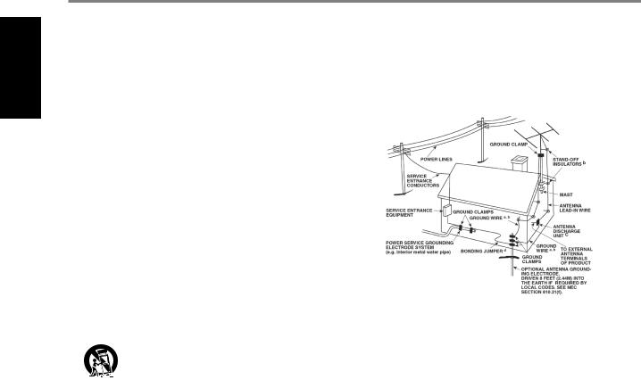
14.Outdoor Antenna Grounding - If an outside antenna or cable system is connected to the product, be sure the antenna or cable system is grounded so as to provide some protection against voltage surges and built-up static charges. Article 810 of the National Electrical Code, ANSI/NFPA 70, provides information with regard to proper grounding of the mast and supporting structure, grounding of the lead-in wire
to an antenna discharge unit, size of grounding conductors, location of antenna discharge unit, connection to grounding electrodes, and requirements for the grounding electrode.
NOTE TO CATV SYSTEM INSTALLER
ThisreminderisprovidedtocalltheCATVsysteminstaller’sattentiontoSection820-40 oftheNECwhichprovidesguidelinesforpropergroundingand,inparticular,specifies thatthecablegroundshallbeconnectedtothegroundingsystemofthebuilding,as closetothepointofcableentryaspractical.
15.Lightning - For added protection for this product during a lightning storm, or when it is left unattended and unused for long periods of time, unplug it from the wall outlet and disconnect the antenna or cable system. This will prevent damage to the product due to lightning and power-line surges.
16.Power Lines - An outside antenna system should not be located in the vicinity of overhead power lines or other electric light or power circuits, or where it can fall into such power lines or circuits. When installing an outside antenna system, extreme care should be taken to keep from touching such power lines or circuits as contact with them might be fatal.
17.Overloading - Do not overload wall outlets, extension cords, or integral convenience receptacles as this can result in a risk of fire or electric shock.
18.Flame Sources - No naked flame sources, such as lighted candles, should be placed on the product.
19.Object and Liquid Entry - Never push objects of any kind into this product through openings as they may touch dangerous voltage points or short-out parts that could result in a fire or electric shock. Never spill liquid of any kind on the product.
20.Headphones - Excessive sound pressure form earphones and headphones can cause hearing loss.
21.Damage Requiring Service - Unplug this product from the wall outlet and refer servicing to qualified service personnel under the following conditions:
a.When the power-supply cord or plug is damaged.
b.If liquid has been spilled, or objects have fallen into the product.
c.If the product has been exposed to rain or water.
d.If the product does not operate normally by following the operating instructions. Adjust only those controls that are covered by the operating instructions as an improper adjustment of other controls may result in damage and will often require extensive work by a qualified technician to restore the product to its normal operation.
e.If the product has been dropped or damaged in any way.
f.When the product exhibits a distinct change in performance-this indicates a need for service.
22.Replacement Parts - When replacement parts are required, be sure the service technician has used replacement parts specified by the manufacturer or have the same characteristics as the original part. Unauthorized substitutions may result in fire, electric shock, or other hazards.
2
IMPORTANT SAFETY INSTRUCTIONS
23.Battery Disposal - When disposing of used batteries, please comply with governmental regulations or environmental public instruction’s rules that apply in your country or area.
24.Safety Check - Upon completion of any service or repairs to this product, ask the service technician to perform safety checks to determine that the product is in proper operating condition.
25.Wall or Ceiling Mounting - The product should be mounted to a wall or ceiling only as recommended by the manufacturer.
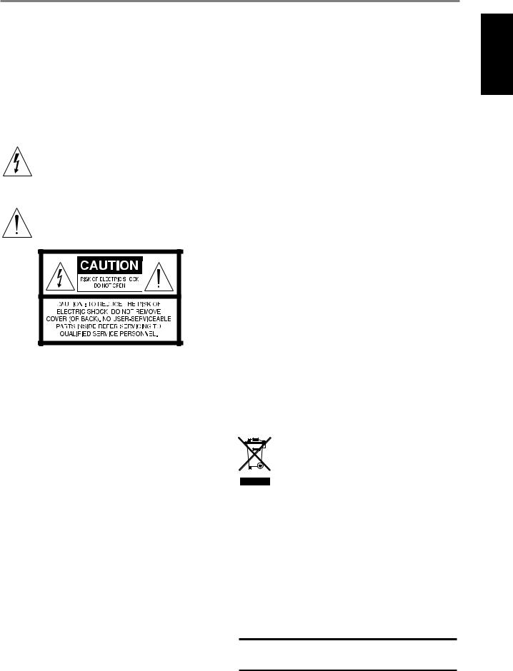
WARNING
The lightning flash with arrowhead symbol, within an equilateral triangle, is intended to alert the user to the presence of uninsulated “dangerous voltage” within the product’s enclosure that may be of sufficient magnitude to constitute a risk of electric shock to persons
The exclamation point within an equilateral triangle is intended to alert the user to the presence of important operating
and maintenance (servicing) instructions in the literature accompanying the appliance.
THE EQUIPMENT MUST BE CONNECTED TO AN EARTHED MAINS SOCKET-OUTLET.
CAUTION REGARDING PLACEMENT
To maintain proper ventilation, be sure to leave a space around the unit (from the largest outer dimensions including projections) than is equal to, or greater than shown below.
Left and Right Panels: 10 cm Rear Panel: 10 cm
Top Panel: 10 cm
FCC STATEMENT
This equipment has been tested and found to comply with the limits for Class B digital device, pursuant to Part 15 of the FCC Rules. These limits are designed to provide reasonable protection against harmful interference in a residential installation. This equipment generates, uses, and can radiate radio frequency energy and, if not installed and used in accordance with the instructions, may cause harmful interference to radio communications. However, there is no guarantee that interference will not occur in a particular installation. If this equipment does cause harmful interference to radio or television reception, which can be determined by turning the equipment off and on, the user is encouraged to try to correct the interference by one or more of the following measures:
•Reorient or relocate the receiving antenna.
•Increase the separation between the equipment and receiver.
•Connect the equipment into an outlet on a circuit different from that to which the receiver is connected.
•Consult the dealer or an experienced radio TV technician for help.
CAUTION
Changes or modifications to this equipment not expressly approved by NAD Electronics for compliance could void the user’s authority to operate this equipment.
CAUTION
To prevent electric shock, match wide blade of plug to wide slot, fully insert.
CAUTION
Marking and rating plate can be found at the rear panel of the apparatus.
WARNING
To reduce the risk of fire or electric shock, do not expose this apparatus to rain or moisture.
The apparatus shall not be exposed to dripping or splashing and that no objects filled with liquids, such as vases, shall be placed on apparatus.
Mains plug is used as disconnect device and it should remain readily operable during intended use. In order to disconnect the apparatus from the mains completely, the mains plug should be disconnected from the mains socket outlet completely.
Battery shall not be exposed to excessive heat such as sunshine, fire or the like.
CAUTION
Danger of explosion if battery is incorrectly replaced. Replace only with the same or equivalent type.
An appliance with a protective earth terminal should be connected to a mains outlet with a protective earth connection.
IF IN DOUBT CONSULT A COMPETENT ELECTRICIAN.
 This product is manufactured to comply with the radio interference requirements of EEC DIRECTIVE 2004/108/EC.
NOTES ON ENVIRONMENTAL PROTECTION
At the end of its useful life, this product must not be disposed of with regular household waste but must be returned to a collection point for the recycling of electrical and electronic equipment. The symbol on the product, user’s manual and packaging point this out.
The materials can be reused in accordance with their markings. Through re-use, recycling of raw materials, or other forms of recycling of old products, you are making an important contribution to the protection of our environment.
Your local administrative office can advise you of the responsible waste disposal point.
RECORD YOUR MODEL NUMBER (NOW, WHILE YOU CAN SEE IT)
The model and serial number of your new M32 are located on the back of the cabinet. For your future convenience, we suggest that you record these numbers here:
Model number : . . . . . . . . . . . . . . . . . . . . . . . . . . . . . . . . . . . . . .
Serial number :. . . . . . . . . . . . . . . . . . . .
NAD is a trademark of NAD Electronics International, a division of Lenbrook Industries Limited Copyright 2017, NAD Electronics International, a division of Lenbrook Industries Limited
ENGLISH
3

ENGLISH
INTRODUCTION
TABLE OF CONTENTS
IMPORTANT SAFETY INSTRUCTIONS . . . . . . . . . . . . . . . . . . . . . . . . . .2
INTRODUCTION
GETTING STARTED. . . . . . . . . . . . . . . . . . . . . . . . 5
WHAT’S IN THE BOX. . . . . . . . . . . . . . . . . . . . . . . . . .5 CHOOSING A LOCATION . . . . . . . . . . . . . . . . . . . . . . . 5 RESTORING M32 TO ITS FACTORY DEFAULT SETTINGS.. . . . . . . . 5
IDENTIFICATION OF CONTROLS |
|
FRONT PANEL.. . . . . . . . . . . . . . . . . . . . . . . . . . 6 |
|
REAR PANEL . . . . . . . . . . . . . . . . . . . . . . . . . . . |
7 |
MDC CLASSIC UPGRADE SLOTS. . . . . . . . . . . . . . . . . . . .9 DD HDM-1 (DIRECT DIGITAL HDMI) . . . . . . . . . . . . . . . . . .9 DD AP 1 (DIRECT DIGITAL ANALOG-PHONO).. . . . . . . . . . . . 9 MDC BluOS. . . . . . . . . . . . . . . . . . . . . . . . . . . . . . 9
OPERATION |
|
USING THE M32. . . . . . . . . . . . . . . . . . . . . . . . . |
10 |
NAVIGATING THE M32 FEATURES AND MAKING CHANGES. . . . . |
10 |
DISPLAY MENU OPTIONS.. . . . . . . . . . . . . . . . . . . . . |
12 |
MAIN. . . . . . . . . . . . . . . . . . . . . . . . . . . . . . . . |
12 |
MEDIA. . . . . . . . . . . . . . . . . . . . . . . . . . . . . . . |
12 |
MODE. . . . . . . . . . . . . . . . . . . . . . . . . . . . . . . . |
12 |
EQ.. . . . . . . . . . . . . . . . . . . . . . . . . . . . . . . . . |
13 |
SETUP. . . . . . . . . . . . . . . . . . . . . . . . . . . . . . . . |
13 |
SPEAKER SETUP. . . . . . . . . . . . . . . . . . . . . . . . . . . |
13 |
SOURCE SETUP.. . . . . . . . . . . . . . . . . . . . . . . . . . |
14 |
THANK YOU FOR CHOOSING NAD.
The M32 DirectDigital DAC Amplifier is an elegant, top-of-the-line, BluOS™ capable integrated amplifier with a host of features that offer maximum flexibility, excellent efficiency, and reduced noise and distortion. Its advanced software-controlled algorithms result in the shortest signal path from source to speaker producing virtually no distortion and a damping factor of over 1,000. This technology is among the fastest and most accurate amplification and error correction available.
Using a proprietary modular design, you can upgrade or expand your M32 as technologies emerge, ensuring a cost-effective way to keep the music “on” into the future.
OTHER FEATURES. . . . . . . . . . . . . . . . . . . . . . . . |
15 |
DIGITAL OUTPUT. . . . . . . . . . . . . . . . . . . . . . . . . . |
15 |
CONTROL SETUP. . . . . . . . . . . . . . . . . . . . . . . . . . |
15 |
LISTENING TO COMPUTER.. . . . . . . . . . . . . . . . . . . . . |
15 |
BluOS MENU . . . . . . . . . . . . . . . . . . . . . . . . . . . . |
16 |
USING THE HTRM 2 REMOTE CONTROL . . . . . . . . . . . . . . |
17 |
CONTROLLING THE M32. . . . . . . . . . . . . . . . . . . . . . |
17 |
LEARNING CODES FROM OTHER REMOTES.. . . . . . . . . . . . |
17 |
PUNCH THROUGH. . . . . . . . . . . . . . . . . . . . . . . . . |
18 |
COPY A COMMAND FROM ANOTHER KEY.. . . . . . . . . . . . . |
18 |
MACRO COMMANDS . . . . . . . . . . . . . . . . . . . . . . . |
18 |
KEY ILLUMINATION TIMEOUT.. . . . . . . . . . . . . . . . . . . |
19 |
CONFIGURING KEY ILLUMINATION. . . . . . . . . . . . . . . . . |
19 |
FACTORY RESET. . . . . . . . . . . . . . . . . . . . . . . . . . . |
19 |
LOADING CODE-LIBRARIES. . . . . . . . . . . . . . . . . . . . . |
20 |
SEARCH MODE. . . . . . . . . . . . . . . . . . . . . . . . . . . |
20 |
CHECKING CODE LIBRARY NUMBER. . . . . . . . . . . . . . . . . |
20 |
SUMMARY OF THE HTRM 2 MODES . . . . . . . . . . . . . . . . . |
20 |
BATTERY INSTALLATION. . . . . . . . . . . . . . . . . . . . . . . |
21 |
SPECIFICATIONS. . . . . . . . . . . . . . . . . . . . . . . . . |
22 |
As with all our products, NAD’s “Music First” design philosophy guided the M32’s design. We have also been careful to ensure that the M32 is as musically transparent, faithful to every detail and spatially accurate as possible, incorporating much of what we’ve learned from more than a quarter-century’s experience designing audio, video and home-theater components.
We encourage you to take a few minutes now to read right through this manual. Investing a little time here at the outset might save you a good deal of time later, and is by far the best way to ensure that you make the most of your investment in the M32.
For warranty information contact your local distributor.
NAD SHALL NOT BE HELD LIABLE FOR ANY TECHNICAL OR USER INTERFACE DISCREPANCIES IN THIS MANUAL. THE M32 OWNER’S MANUAL MAY BE SUBJECT TO CHANGE WITHOUT PRIOR NOTICE. CHECK OUT THE NAD WEBSITE FOR THE LATEST VERSION OF THE M32 OWNER’S MANUAL.
4
|
|
INTRODUCTION |
|
|
GETTING STARTED |
|
|
|
WHAT’S IN THE BOX |
|
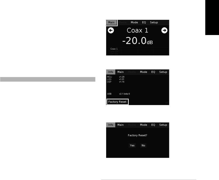
RESTORING M32 TO ITS FACTORY DEFAULT SETTINGS |
Packed with your M32 you will find |
|
1 Press and hold front panel’s “Main” display. |
•Two detachable mains power cord
•The HTRM 2 remote control with 4 AA batteries
•Four magnetic feet
•Cleaning cloth
•USB flash drive
•Quick Setup Guide
SAVE THE PACKAGING
Please save the box and the packaging that came with the M32. Should you move or need to transport your M32, this is the safest container to use.
We’ve seen too many otherwise perfect components damaged in transit 2 Select “Factory Reset” display option. for lack of a proper shipping carton, so please: Save that box!
CHOOSING A LOCATION
Choose a location that is well ventilated (with at least several inches to both sides and behind), and will provide a clear line of sight, within 25 feet / 8 meters, between the M32’s front panel and your primary listening/ viewing position - this will ensure reliable infrared remote control communications. The M32 generates a modest amount of heat, but nothing that should trouble adjacent components.
3 Select “Yes” to reset your M32 to factory default settings or “No” if you decide not to reset your M32.
4 Factory reset is complete when the M32 goes to standby mode.
IMPORTANT NOTE
After factory reset, wait out for at least one minute to switch back the M32 from standby mode to operating mode. This wait time can be bypassed by turning OFF/ON the rear panel power switch and then press Standby button.
ENGLISH
FRANÇAIS
ESPAÑOL
ITALIANO
SVENSKA NEDERLANDS DEUTSCH
РУССКИЙ
5
IDENTIFICATION OF CONTROLS
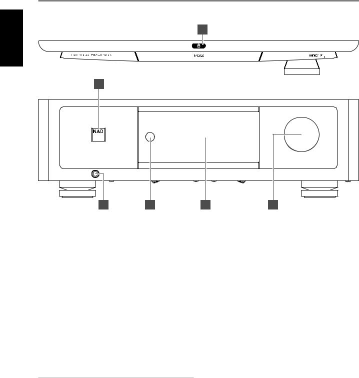
FRONT PANEL
ENGLISH |
|
|
|
2 |
|
|
|
|
|
|
|
|
|
1 |
|
|
|
|
|
|
|
|
© NAD M32 |
|
|
3 |
4 |
5 |
6 |
1 |
POWER INDICATOR |
|
4 |
REMOTE SENSOR |
|
|
• |
This indicator will be amber when the M32 is in standby mode. |
|
• Point the HTRM 2 remote control at the remote sensor and press |
|
|
• |
When the M32 is powered up from standby mode, this indicator |
|
the appropriate buttons. |
|
|
|
will change from amber to bright white color. |
|
|
• Do not expose the remote sensor of the M32 to a strong light |
|
|
|
|
|
source such as direct sunlight or illumination. If you do so, you may |
2 |
o(STANDBY) |
|
|
not be able to operate the M32 with the remote control. |
|
|
• |
Touch the o (Standby) button on top of the unit to switch the |
|
Distance: About 23 ft. (7 m.) from the front of the remote sensor. |
|
|
|
M32 ON from standby mode. The Power indicator will change from |
|
Angle: About 30 degrees in each direction of the front of the |
|
|
|
amber to bright/white color. |
|
|
remote sensor. |
|
• |
Press and hold o (Standby) button until M32 switches back to |
|
|
|
|
|
standby mode. |
|
5 DISPLAY (TOUCH PANEL DISPLAY) |
|
|
• |
One press or touch of the o (Standby) button will not switch the |
|
• Displays visual and menu information according to the settings |
|
|
|
M32 to standby mode. This is intended to avoid unintentionally |
|
selected. |
|
|
|
setting the M32 to standby mode if one happens to just touch or |
|
• The following display options are accessible via the touch panel |
|
|
|
press the o (Standby) button at operating mode. |
|
display - Main, Media, Mode, EQ and Setup. |
|
|
• |
The Power indicator will change to amber color at standby mode. |
|
• Touch the screen to select any of the display options, to see their |
|
|
• |
The o (Standby) button cannot activate the M32 if the rear panel |
|
corresponding menu options, or settings. |
|
|
|
POWER switch is off. |
|
|
|
|
• |
Refer also to +12V TRIGGER - REAR PANEL. |
|
6 |
VOLUME |
|
|
|
|
|
• The VOLUME control adjusts the overall loudness of the signal sent |
IMPORTANT NOTES |
|
|
to the loudspeakers. The Volume control is characterized by perfect |
||
|
For the o(Standby) button to activate, the following must occur: |
|
signal tracking and channel balance. It provides a highly linear and |
||
|
a |
The supplied power cord from the M32 must be plugged in to a |
|
low noise operation. |
|
|
|
power source. |
|
|
• Turn clockwise to increase the volume level and counter clockwise |
|
b |
The rear panel POWER switch must be set to ON. |
|
to lower it. |
|
|
|
|
|
|
• The default volume level is -20dB. |
3 |
HEADPHONE |
|
|
|
|
|
• |
A 1/4” stereo jack socket is supplied for headphone listening and will |
|
|
|
|
|
work with conventional headphones of any impedance. |
|
|
|
|
• |
The volume, tone and balance controls are operative for |
|
|
|
|
|
headphone listening. Use a suitable adapter to connect |
|
|
|
|
|
headphones with other types of sockets, such as 3.5mm “personal |
|
|
|
|
|
stereo” jack plugs. |
|
|
|
6 |
|
|
|
|
|

IDENTIFICATION OF CONTROLS
REAR PANEL
|
1 |
|
2 |
|
3 |
4 |
|
5 |
|
6 |
7 |
ENGLISH |
|
|
|
|
|
|
|
|
|
|
|
|
|
|
COAX1 |
|
|
|
|
|
|
|
|
|
|
|
n |
|
n |
n |
|
|
|
|
|
|
|
|
|
o |
COAX2 |
o |
o |
|
|
|
|
|
|
|
|
|
i |
i |
i |
|
|
|
|
|
|
|
|
|
|
t |
t |
t |
|
|
|
|
|
|
|
|
|
|
c |
|
c |
c |
|
|
|
|
|
|
|
|
|
r u |
|
r u |
r u |
|
|
|
|
|
|
|
|
|
a n r |
|
a n r |
a n r |
|
|
|
|
|
|
|
|
|
d u l s i g n s t |
OPT1 |
d u l s i g n s t |
d u l s i g n s t |
|
|
|
|
|
|
|
|
|
o e o |
|
o e o |
o e o |
|
|
|
|
|
|
|
|
|
M D C |
|
M D C |
M D C |
|
|
|
|
|
|
|
|
|
|
|
|
|
|
|
|
INPUT |
|
OUTPUT |
|
|
|
|
OPT2 |
|
|
|
|
PHONO |
LINE 1 |
LINE 2 |
PRE-OUT/SUBW |
|
|
|
|
|
|
|
|
|
L |
L |
L |
L |
|
|
|
|
|
|
|
|
|
MM |
|
|
|
|
|
|
|
|
|
COMPUTER |
SERVICE |
|
R |
R |
R |
R |
|
|
|
|
AES/EUB IN |
|
|
|
|
|
|
|
|
|
|
|
|
|
|
|
|
|
|
|
|
|
|
|
© NAD M32 |
|
8 |
|
9 |
10 |
11 |
|
|
12 |
13 |
14 |
15 |
|
ATTENTION!
Please ensure that the M32 is powered off or unplugged from the main power source before making any connections. It is also advisable to power down or unplug all associated components while making or breaking any signal or AC power connections.
1COAX 1-2, OPT 1-2
•Connect to the corresponding optical or coaxial digital output of sources such as CD or BD/DVD players, digital cable box, digital tuners and other applicable components.
2COAXIAL OUT, OPTICAL OUT,
•Connect the optical or coaxial DIGITAL OUT to a corresponding digital audio input of compatible devices such as receivers, computer soundcards or other digital processors.
NOTE
Only digital sources can be streamed through COAXIAL/OPTICAL DIGITAL OUT.
3+12V TRIGGER
+12V TRIGGER OUT
The +12V TRIGGER OUT is used for controlling external equipment equipped with a +12V trigger input.
•Connect this +12V TRIGGER OUT to the other equipment’s corresponding +12V DC input jack using a mono cable with 3.5mm male plug.
•This output will be 12V when the M32 is ON and 0V when it is either OFF or in standby mode.
+12V TRIGGER IN
With this input triggered by a 12V DC supply, the M32 can be switched ON remotely from Standby Mode by compatible devices such as amplifiers, preamplifiers, receivers, etc. If the 12V DC supply is cut off, the M32 will return to standby mode.
•Connect this +12V Trigger input to the remote device’s corresponding +12V DC output jack using a mono cable with 3.5mm male plug. The controlling device must be equipped with a +12V trigger output to use this feature.
4IR IN
•This input is connected to the output of an IR (infrared) repeater (Xantech or similar) or the IR output of another component to allow control of the M32 from a remote location.
5RS 232
NAD is a certified partner of AMX and Crestron and fully supports these external devices. Check out the NAD website for information about AMX and Crestron compatibility with NAD. See your NAD audio specialist for more information.
•Connect this interface using RS-232 serial cable (not supplied) to any Windows compatible PC to allow remote control of the M32 via compatible external controllers.
•Refer to the NAD website for information about RS232 Protocol documents and PC interface program.
6SPEAKERS
•The M32 has two sets of SPEAKER connections which are identical in function (parallel connection). They allow for bi-wiring.
•Connect M32’s Right speaker terminals marked “R +” and “R-” to the corresponding “+” and “-“ terminals of your designated right speaker. Repeat the same for M32’s Left speaker terminals and corresponding left speaker.
•Double check the speaker connections before powering up the M32.
BI-WIRING
Most high quality loudspeakers offer the option of Bi-wiring. This separates the High Frequency (HF) crossover from the Low Frequency (LF) crossover. This offers enhanced performance by preventing LF returned currents from affecting the HF performance. To bi-wire, remove the “links” at the loudspeaker that connect the LF and HF sections (these are provided for convenience when a single wire connection is used).
NOTES
•Use 16 gauge (American Wire Gauge or AWG) or lower stranded wire. Connections to the M32 can be made with banana-type plugs.
•Bare wire or pins can also be used by loosening the terminal’s plastic nut, making a clean, neat connection and re-tightening. To minimize the danger of a short circuit, ensure that only 1/2-inch of exposed wire or pin is used to connect and no loose strands of speaker wire.
7
ENGLISH
IDENTIFICATION OF CONTROLS
REAR PANEL
7POWER
•The POWER switch supplies the master AC mains power for the M32.
•When the POWER switch is set to ON position, the M32 goes to standby mode as shown by the amber status condition of the front panel Power indicator. Press the front panel Standby button or HTRM 2’s remote control’s [ON] button to switch ON the M32 from standby mode.
•If you do not intend to use the M32 for long periods of time (such as when on vacation), switch off the POWER switch.
•With POWER switched off, neither the front panel Standby button nor HTRM 2 remote control’s [ON] button can activate the M32.
8DIGITAL AES/EBU
•Connect SACD/CD Players or processors to this XLR connector for digital audio streaming.
•High-end sources with higher sampling rates (176kHz and 192kHz) should be connected to the AES/EBU IN connector.
9COMPUTER
•Use a Type A to Type B cable connector (not supplied), to interface computer audio to this asynchronous Type B USB input to directly stream 24/96 PCM content from your PC or MAC.
•The Type A-style connector is a flat, rectangular interface.
•The Type B-style interface is square in shape and has beveled corners on the top ends of the connector.
•Refer to LISTENING TO COMPUTER in the OTHER FEATURES section on the OPERATION page.
10SERVICE
Use for servicing purposes only. Not for consumer use.
11INPUT
PHONO: Input for a Moving Magnet (MM) phono cartridge. Connect the twin RCA lead from your turntable to this input if you are using a Moving Magnet cartridge.
LINE1, LINE 2: Input for line level sources such as CD player, tuner or any compatible devices. Use a twin RCA-to-RCA lead to connect the source device’s left and right “Audio Output” to this input.
12OUTPUT (PRE-OUT/SUBW)
•These output terminals have dual function. They are used either as PRE-OUT or SUBWOOFER terminals.
•The M32 and associated external devices must be turned OFF always before connecting or disconnecting anything to the OUTPUT sockets.
IMPORTANT
Set the “Sub Output” option under “Speaker Setup” settings to “ON” for the OUTPUT terminals to function as Subwoofer out. On the other hand, the OUTPUT terminals will function as PRE-OUT if the “Sub Output” option is set to “OFF”.
PRE-OUT
•The PRE OUT/SUBW sockets make it possible for the M32 to be used as a full range preamplifier to an external power amplifier.
•Use a dual RCA cable to connect PRE-OUT/SUBW to the corresponding analog audio input of compatible devices such as amplifiers, receivers or other applicable devices.
•PRE-OUT/SUBW will be affected by the M32’s volume control settings. Turn the VOLUME control to adjust the output level of the PRE OUT/SUBW sockets.
SUBWOOFER
•Use a dual RCA cable to connect PRE OUT/SUBW to the low level input of a powered subwoofer.
•Low frequency information up to 200Hz is sent to the connected subwoofer via PRE OUT/SUBW.
13AC MAINS INPUT
•The M32 comes supplied with two separate mains power cords. Select the mains power cord appropriate for your region.
•Before connecting the plug to the mains power source, ensure that it is firmly connected to the M32’s AC Mains input socket.
•Always disconnect the mains power plug from the mains power source before disconnecting the cable from the M32’s AC Mains input socket.
14FUSE HOLDER
•Only qualified NAD service technicians can have access to this fuse holder. Opening this fuse holder may cause damage thus voiding the warranty of your M32.
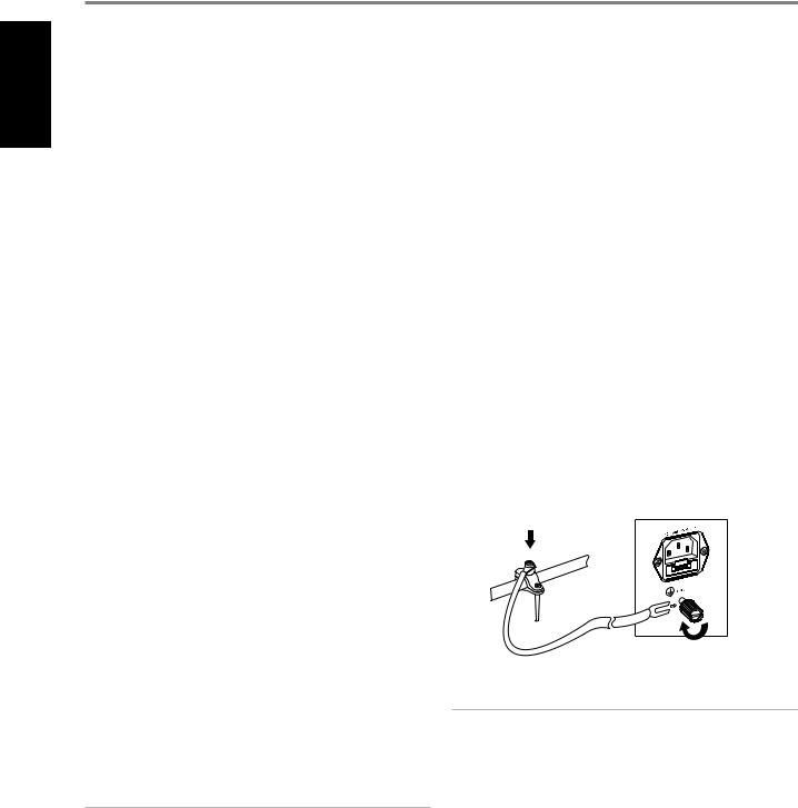
15GROUND TERMINAL
•Ensure that the M32 is plugged-in to a grounded AC wall outlet.
•If necessary, use this ground terminal to connect to ground a phono or turntable source for PHONO input.
•If a separate earth ground is necessary, use this terminal to ground your M32. The M32 can be connected to ground by connecting a ground lead wire or similar to this terminal. After insertion, tighten the terminal to secure the lead.
NOTES
•The above illustration shows the M32 being connected to ground via a metal water pipe. There maybe other grounding conductor points in your home. Consult with a licensed electrician to locate or install a grounding conductor in your home. NAD is not responsible for any malfunction, damage or costs associated with the installation, connection, or grounding of your M32.
•The grounding wire is not supplied with your M32.
8
Loading...