


 ® C315BEE
Integrated Amplifier
Owner’s Manual Manuel d’Installation Bedienungsanleitung Gebruikershandleiding Manual del Usuario Manuale delle Istruzioni
Инструкция по эксплуатации Bruksanvisning
ENGLISH
FRANÇAIS
ESPAÑOL NEDERLANDS DEUTSCH
ITALIANO
РУССКИЙ
SVENSKA
ENGLISH
FRANÇAIS
ESPAÑOL NEDERLANDS DEUTSCH
ITALIANO
РУССКИЙ
SVENSKA
IMPORTANT SAFETY INSTRUCTIONS
Save these instructions for later use.
Follow all warnings and instructions marked on the audio equipment.
1Read instructions - All the safety and operating instructions should be read before the product is operated.
2Retain instructions - The safety and operating instructions should be retained for future reference.
3Heed Warnings - All warnings on the product and in the operating instructions should be adhered to.
4Follow Instructions - All operating and use instructions should be followed.
5Cleaning - Unplug this product from the wall outlet before cleaning. Do not use liquid cleaners or aerosol cleaners. Use a damp cloth for cleaning.
6Attachments - Do not use attachments not recommended by the product manufacturer as they may cause hazards.
7Water and Moisture - Do not use this product near water-for example, near a bath tub, wash bowl, kitchen sink, or laundry tub; in a wet basement; or near a swimming pool; and the like.
8Accessories - Do not place this product on an unstable cart, stand, tripod, bracket, or table. The product may fall, causing serious injury to a child or adult, and serious damage to the product. Use only with a cart, stand, tripod, bracket, or table recommended by the manufacturer, or sold with the product. Any mounting of the product should follow the manufacturer’s instructions, and should use a mounting accessory recommended by the manufacturer.
9A product and cart combination should be moved with care.
Quick stops, excessive force, and uneven surfaces may cause the product and cart combination to overturn.
10Ventilation - Slots and openings in the cabinet are provided for ventilation and to ensure reliable operation of the product and to protect it from overheating, and these openings must not be blocked or covered. The openings should never be blocked by placing the product on a bed, sofa, rug, or other similar surface. This product should not be placed in a built-in installation such as a bookcase or rack unless proper ventilation is provided or the manufacturer’s instructions have been adhered to.
11Power Sources - This product should be operated only from the type of power source indicated on the marking label. If you are not sure of the type of power supply to your home, consult your product dealer or local power company. The primary method of isolating the amplifier from the mains supply is to disconnect the mains plug. Ensure that the mains plug remains accessible at all times. Unplug the AC power cord from the AC outlet if the unit will not be used for several months or more.
12Grounding or Polarization - This product may be equipped with a polarized alternating-current line plug (a plug having one blade wider than the other). This plug will fit into the power outlet only one way. This is a safety feature. If you are unable to insert the plug fully into the outlet, try reversing the plug. If the plug should still fail to fit, contact your electrician to replace your obsolete outlet. Do not defeat the safety purpose of the polarized plug.
13Power - Cord Protection - Power-supply cords should be routed so that they are not likely to be walked on or pinched by items placed upon or against them, paying particular attention to cords at plugs, convenience receptacles, and the point where they exit from the product.
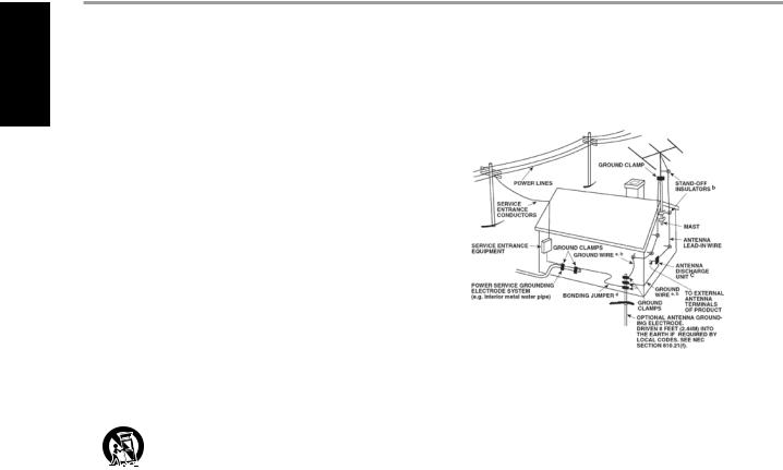
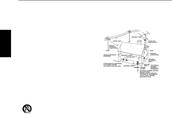
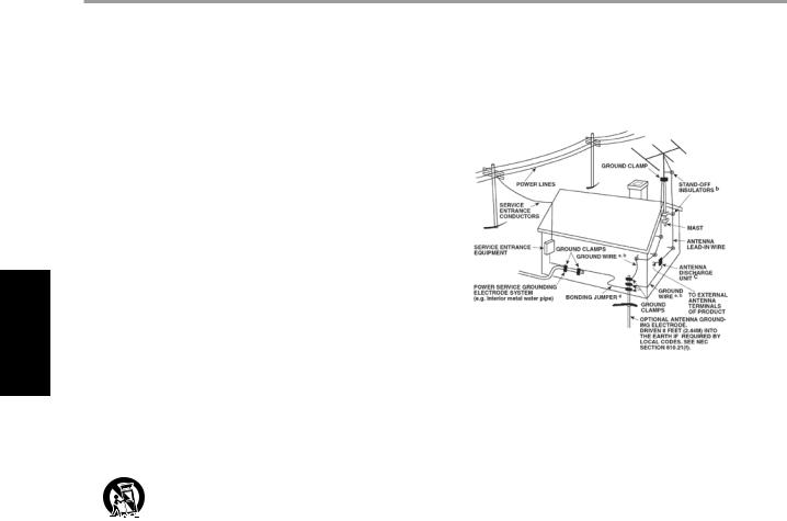
14Outdoor Antenna Grounding - If an outside antenna or cable system is connected to the product, be sure the antenna or cable system is grounded so as to provide some protection against voltage surges and built-up static charges. Article 810 of the National Electrical Code, ANSI/NFPA 70, provides information with regard to proper grounding of the mast and supporting structure, grounding of the lead-in wire to an antenna discharge unit, size of grounding conductors, location of antenna discharge unit, connection to grounding electrodes, and requirements for the grounding electrode.
NOTE TO CATV SYSTEM INSTALLER
This reminder is provided to call the CATV system installer’s attention to Section 820-40 of the NEC which provides guidelines for proper grounding and, in particular, specifies that the cable ground shall be connected to the grounding system of the building, as close to the point of cable entry as practical.
15Lightning - For added protection for this product during a lightning storm, or when it is left unattended and unused for long periods of time, unplug it from the wall outlet and disconnect the antenna or cable system. This will prevent damage to the product due to lightning and power-line surges.
16Power Lines - An outside antenna system should not be located in the vicinity of overhead power lines or other electric light or power circuits, or where it can fall into such power lines or circuits. When installing an outside antenna system, extreme care should be taken to keep from touching such power lines or circuits as contact with them might be fatal.
17Overloading - Do not overload wall outlets, extension cords, or integral convenience receptacles as this can result in a risk of fire or electric shock.
18Object and Liquid Entry - Never push objects of any kind into this product through openings as they may touch dangerous voltage points or short-out parts that could result in a fire or electric shock. Never spill liquid of any kind on the product.
WARNING: The apparatus shall noT be exposed to dripping or splashing, and objects filled with liquids, such as vases, shall not be placed on the apparatus. As with any electronic products, use care not to spill liquids into any part of the system. Liquids can cause a failure and/or a fire hazard.
19Damage Requiring Service - Unplug this product from the wall outlet and refer servicing to qualified service personnel under the following conditions:
a)When the power-supply cord or plug is damaged.
b)If liquid has been spilled, or objects have fallen into the product.
c)If the product has been exposed to rain or water.
d)If the product does not operate normally by following the operating instructions. Adjust only those controls that are covered by the operating instructions as
an improper adjustment of other controls may result in damage and will often require extensive work by a qualified technician to restore the product to its normal operation.
e)If the product has been dropped or damaged in any way.
f)when the product exhibits a distinct change in performance-this indicates a need for service.
20Replacement Parts - When replacement parts are required, be sure the service technician has used replacement parts specified by the manufacturer or have the same characteristics as the original part. Unauthorized substitutions may result in fire, electric shock, or other hazards.
21Safety Check - Upon completion of any service or repairs to this product, ask the service technician to perform safety checks to determine that the product is in proper operating condition.
22Wall or Ceiling Mounting - The product should be mounted to a wall or ceiling only as recommended by the manufacturer.
IMPORTANT SAFETY INSTRUCTIONS
WARNING
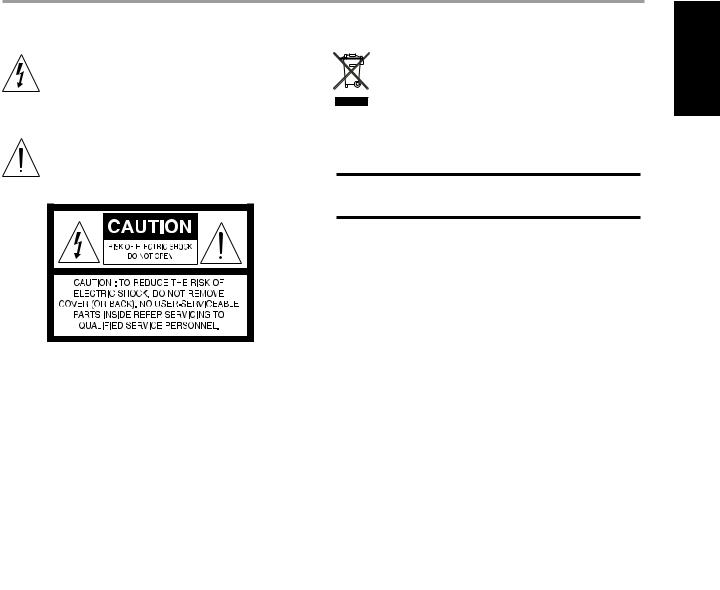
TO PREVENT FIRE OR SHOCK HAZARD, DO NOT EXPOSE THIS APPLIANCE TO RAIN OR MOISTURE. THE LIGHTNING FLASH WITH ARROWHEAD SYMBOL, WITHIN AN EQUILATERAL TRIANGLE, IS INTENDED TO ALERT THE USER TO THE PRESENCE OF UNINSULATED“DANGEROUS VOLTAGE” WITHIN THE PRODUCT’S ENCLOSURE THAT MAY BE OF SUFFICIENT MAGNITUDE TO CONSTITUTE A RISK OF ELECTRIC SHOCK TO PERSONS.
THE EXCLAMATION POINT WITHIN AN EQUILATERAL TRIANGLE IS INTENDED TO ALERT THE USER TO THE PRESENCE OF IMPORTANT OPERATING AND MAINTENANCE (SERVICING) INSTRUCTIONS IN THE LITERATURE ACCOMPANYING THE APPLIANCE
CAUTION
Changes or modifications to this equipment not expressly approved by NAD Electronics for compliance could void the user’s authority to operate this equipment.
CAUTION REGARDING PLACEMENT
To maintain proper ventilation, be sure to leave a space around the unit (from the largest outer dimensions including projections) equal to, or greater than, shown below.
Left and Right Panels : 10 cm Rear Panel : 10 cm
Top Panel : 50 cm
IMPORTANT INFORMATION FOR UK CUSTOMERS
DO NOT cut off the mains plug from this equipment. If the plug fitted is not suitable for the power points in your home or the cable is too short to reach a power point, then obtain an appropriate safety
approved extension lead or consult your dealer. If, nonetheless, the mains plug is cut off, REMOVE THE FUSE and dispose of the PLUG immediately, to avoid possible shock hazard by inadvertent connection to the mains supply. If this product is not provided with a mains plug, or one has to be fitted, then follow the instructions given below:
IMPORTANT
DO NOT make any connection to the larger terminal which is marked with the letter ‘E’ or by the safety earth symbol or coloured GREEN or GREEN AND YELLOW.
The wires in the mains lead on this product are coloured in accordance with the following code:
BLUE - NEUTRAL
BROWN - LIVE
As these colours may not correspond with the coloured markings identifying the terminals in your plug, proceed as follows:
The BLUE wire must be connected to the terminal marked with the letter ‘N’ or coloured BLACK.
The BROWN wire must be connected to the terminal marked with the letter ‘L’ or coloured RED
When replacing the fuse, only a correctly rated and approved type should be used, and be sure to re-fit the fuse cover.
IF IN DOUBT CONSULT A COMPETENT ELECTRICIAN
This product is manufactured to comply with the radio interference requirements of EEC DIRECTIVE 89/68/EEC and 2006/95/EEC.
NOTES ON ENVIRONMENTAL PROTECTION
At the end of its useful life, this product must not be disposed of with regular household waste but must be returned to a collection point for
the recycling of electrical and electronic equipment. The symbol on the product, user’s manual and packaging, point this out.
The materials can be reused in accordance with their markings. Through re-use, recycling of raw materials, or other forms of recycling of old products, you are making an important contribution to the protection of our environment.
Your local administrative office can advise you of the responsible waste disposal point.
Model No. :________________________
Serial No. :_________________
ENGLISH
FRANÇAIS
ESPAÑOL NEDERLANDS DEUTSCH
ITALIANO
РУССКИЙ
SVENSKA

ENGLISH
FRANÇAIS
ESPAÑOL NEDERLANDS DEUTSCH
ITALIANO
РУССКИЙ
SVENSKA
Preparation |
|
|
|
|
|
|
|
|
|
|
|
|
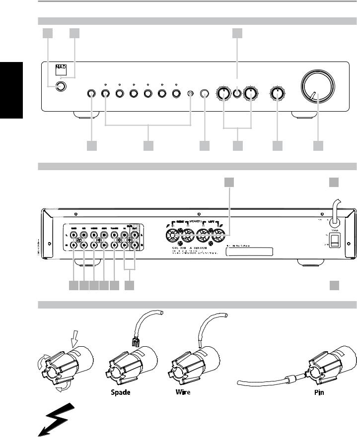
FRONT PANEL CONTROLS (FIGURE 1) |
|
|
|
|
|
|
|
|
||||
1 |
2 |
|
|
|
|
|
|
|
7 |
|
|
|
|
Stereo Integrated Amplifier C 315BEE |
|
|
|
|
|
|
|
|
VOLUME |
||
|
|
|
|
|
|
|
|
|
|
|||
|
|
|
|
|
|
|
|
BASS |
TONE |
TREBLE |
BALANCE |
|
|
|
|
|
|
|
|
|
DEFEAT |
|
|||
|
PHONES |
TAPE |
TUNER |
AUX |
VIDEO |
CD |
DISC |
MP |
|
|
|
|
© NAD C 315BEE |
|
|
|
|
|
|
|
|
|
|
|
|
|
3 |
|
|
|
4 |
|
|
5 |
6 |
|
8 |
9 |
REAR PANEL CONNECTIONS (FIGURE 2)
7 |
8 |
1 |
2 |
3 |
4 |
5 |
6 |
9 |
BARE WIRES AND PIN CONNECTORS (FIGURE 3)
Warning
The Terminals marked with this symbol are hazardous live. External wiring connected to these terminals requires installation by an instructed person or the use of ready-made leads or cords.
NAD is a trademark of NAD Electronics International, a division of Lenbrook Industries Limited
Copyright 2007, NAD Electronics International, a division of Lenbrook Industries Limited

Operation
NOTES ON INSTALLATION
Your NAD C315BEE should be placed on a firm, level surface. Avoid placing the unit in direct sunlight or near sources of heat and damp. Allow adequate ventilation. Do not place the unit on a soft surface like a carpet. Do not place it in an enclosed position such a bookcase or cabinet that may impede the air-flow through the ventilation slots. Make sure the unit is switched off before making any connections.
The RCA sockets on your NAD C315BEE are colour coded for convenience. Red and white are Right and Left audio respectively.
Use high quality leads and sockets for optimum performance and reliability. Ensure that leads and sockets are not damaged in any way and all sockets are firmly pushed home.
For best performance, use quality speaker leads of 16 gauge (1.5mm) thickness or more. If the unit is not going to be used for some time, disconnect the plug from the AC socket.
Should water get into your NAD C315BEE, shut off the power to the unit and remove the plug from the AC socket. Have the unit inspected by a qualified service technician before attempting to use it again.
DO NOT REMOVE THE COVER, THERE ARE NO USER-SERVICEABLE PARTS INSIDE.
Use a dry soft cloth to clean the unit. If necessary, lightly dampen the cloth with soapy water. Do not use solutions containing benzol or other volatile agents.
QUICK START
1Connect the speakers to the rear Speaker terminals and sources to the relevant rear input sockets.
2Plug in the AC power cord.
3Switch to ON, the POWER button on the rear panel, to turn the C315BEE to standby.
4Press the front panel Standby button to turn the NAD C315BEE on.
5Press the required input selector.
FRONT PANEL CONTROLS (FIGURE 1)
1.Standby Button : The Standby Button turns on and to standby the C315BEE. This button will only function when the Power/Standby/ Protection LED is either amber representing the standby state, or green representing the on-state.
2Power/Standby/Protection LED : Upon switching the power on, the LED will light up red for a few seconds before the protection circuit is deactivated. The LED will then turn green, representing normal operation. In cases of serious abuse of the amplifier, such as overheating, excessively low loudspeaker impedance, short circuit etc. the amplifier will engage its Protection circuitry, indicated by the LED turning from green to red, and the sound being muted. In such a case, turn the amplifier off by the rear panel POWER switch, wait for it to cool down and/or check the speaker connections, making sure the overall loudspeaker impedance doesn’t go below 4 ohms. Once the cause for the protection circuitry to engage has been removed, switch ON the rear POWER button and then the Standby Button to resume normal operation.
3Headphone socket :A 1/4” stereo jack socket is supplied for headphone listening and will work with conventional headphones of any impedance. Inserting a headphone jack into this socket automatically switches off the loudspeakers. The volume, tone and balance controls are operative for headphone listening. Use a suitable adaptor to connect headphones with other types of sockets, such as 3.5mm stereo ‘personal stereo’ jack plugs.
SAFETY NOTES
•Make certain that the volume control is turned to minimum (fully anticlockwise) before connecting or disconnecting headphones. Listening at high levels can damage your hearing.
•Excessive sound pressure from earphones or headphones can cause hearing loss.
4Input selectors : These buttons select the active input to the NAD C315BEE and the signal sent to the loudspeakers and the Tape outputs. The buttons on the remote control handset duplicate these buttons. Green LEDs just above each button will indicate which input is currently selected.
TAPE Selects the output from a tape recorder when playing back tape recordings being made through the Tape sockets.
TUNER Selects the tuner (or other line-level source) connected to the Tuner sockets as the active input.
AUX Selects a line-level source connected to the AUX sockets as the active input.
VIDEO Selects the VCR (or stereo TV/Satellite/Cable receiver) connected to the VIDEO sockets as the active input.
CD Selects the CD (or other line-level source) connected to the CD sockets as the active input.
DISC/MP (Media Player) Selects a line-level source connected to the DISC sockets as the active input. When a 3.5mm stereo plug is inserted into the MP socket, the indicator above the socket will illuminate, and the DISC line-level source will be disconnected. It is recommended
to mute the volume or switch to a different input before plugging/ unplugging the external Media Player cable
5Infra-red remote control command receiver :The infrared sensor, located behind this circular window, receives commands from the remote control. There must be a clear line-of-sight path from the remote control to this window; if that path is obstructed, the remote control may not work.
NOTES
Direct sunlight or very bright ambient lighting may affect the operating range and angle for the remote control handset.
The remote control handset with the C315BEE supplied is of a universal NAD type, designed to operate several NAD models.
6Tone controls :The NAD C315BEE is fitted with BASS and TREBLE tone controls to adjust the tonal balance of your system.
The 12 o’clock position is‘flat’ with no boost or cut, and an indent indicates this position. Rotate the control clockwise to increase the amount of Bass or Treble. Rotate the control anti-clockwise to decrease the amount of Bass or Treble. The Tone controls do not affect recordings made using the Tape outputs but will affect the signal going to the Speakers.
7Tone defeat : The TONE DEFEAT switch by-passes the tone control section of the NAD C315BEE. If the Tone Controls are not normally used and left in the 12 o’clock position, then it is advisable to switch out
the Tone Control section altogether by using this switch. In the ‘out’ position, the Tone Control circuits are active, pushing the TONE DEFEAT switch ‘in’ bypasses the Tone Control section.
ENGLISH
FRANÇAIS
ESPAÑOL NEDERLANDS DEUTSCH
ITALIANO
РУССКИЙ
SVENSKA

ENGLISH
FRANÇAIS
ESPAÑOL NEDERLANDS DEUTSCH
ITALIANO
РУССКИЙ
SVENSKA
Operation
8Balance : The BALANCE control adjusts the relative levels of the left and right speakers. The 12 o’clock position provides equal level to the left and right channels. A detent indicates this position.
Rotating the control clockwise moves the balance towards the right. Rotating the control anti-clockwise moves the balance to the left. The BALANCE control does not affect recordings made using the Tape outputs but will affect the signal going to the Speakers.
9Volume : The VOLUME control adjusts the overall loudness of the signals being fed to the loudspeakers. It is motor driven and can be adjusted from the remote control handset. The VOLUME control does not affect recordings made using the Tape outputs but will affect the signal going to the Speakers.
On the remote control handset, press the MUTE button to temporarily switch off the sound to the speakers and headphones. Mute mode is indicated by the active input LED flashing. Press the MUTE button again to restore sound. Mute does not affect recordings made using the Tape outputs but will affect the signal going to the Speakers.
REAR PANEL CONNECTIONS (FIGURE 2)
1Disc input : Input for additional line level input signals such as CD, Mini Disc player or the output signal from a step-up amplifier for a turntable. Use a twin RCA-to-RCA lead to connect the auxiliary unit’s left and right ‘Audio Outputs’ to this input.
NOTES
When a 3.5mm stereo plug is inserted into the Front Panel MP socket, the indicator above the socket will illuminate, and the DISC line-level source will be disconnected.
It is recommended to mute the volume or switch to a different input before plugging/unplugging the external Media Player cable.
2CD input : Input for a CD or other line-level signal source. Use a twin RCA-to-RCA lead to connect the CD player’s left and right ‘Audio Outputs’ to this input. The NAD C315BEE only accepts analogue signals from your CD player.
3Video input : Input for the audio signal from a stereo VCR (or stereo TV/Satellite/Cable receiver) or other line-level audio source. Using twin RCA-to-RCA leads, connect to the left and right ‘Audio Outputs’ of the unit to these inputs. Note: These are audio inputs only.
4AUX input : Input for additional line level input signals such as another CD player. Use a twin RCA-to-RCA lead to connect the auxiliary unit’s left and right ‘Audio Outputs’ to this input.
5Tuner input : Input for a tuner or other line-level signal source. Use a twin RCA-to-RCA lead to connect the tuner left and right ‘Audio Outputs’ to this input.
6Tape In/Out : Connections for analogue recording and playback to an audio tape recorder of any type. Using twin RCA-to-RCA leads, connect to the left and right ‘Audio Output’ of the tape machine to the TAPE
IN sockets for playback and tape monitoring. Connect the left and right ‘Audio Input’ of the tape machine to the TAPE OUT sockets for recording.
TO MAKE A RECORDING
When any source is selected, its signal is also fed directly to any tape machine connected to the TAPE OUTPUT for recording.
7Speakers : Speaker terminals for speakers with an impedance of 4 ohms or more. Connect the right speaker to the terminals marked ‘R +’ and ‘R-’ ensuring that the ‘R+’ is connected to the ‘+’ terminal on your loudspeaker and the ‘R-’ is connected to the loudspeaker’s ‘-’ terminal. Connect the terminals marked ‘L+’ and ‘L-’ to the left speaker in the same way.
Always use heavy duty (16 gauge; 1.5mm, or thicker) stranded wire to connect loudspeakers to your NAD C315BEE. The high-current binding post terminals can be used as a screw terminal for cables terminating in spade or pin sockets or for cables with bare wire ends.
BARE WIRES AND PIN CONNECTORS (FIGURE 3)
Bare wires and pin sockets should be inserted into the hole in the shaft of the terminal. Unscrew the speaker terminal’s plastic bushing until the hole in the screw shaft is revealed. Insert the pin or bare cable end into the hole and secure the cable by tightening down the terminal’s bushing. Ensure bare wire from the speaker cables does not touch the back panel or another socket. Ensure that there is only 1/2” (1cm) of bare cable or pin and no loose strands of speakers wire.
8AC line cord : Plug the AC power cord into a live AC wall socket. Make sure all connections have been made before connecting to mains.
9POWER Switch : The POWER switch supplies the master AC mains power for the C315BEE. When this switch is in the ON position the C315BEE is in standby as shown by the amber Status Condition L.E.D. above the power switch on the front panel. If you intend not to use the amplifier for long periods of time, switch the POWER switch to the OFF position.
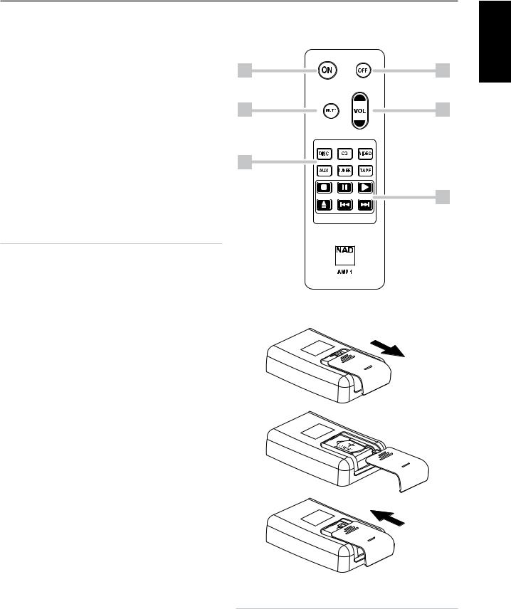
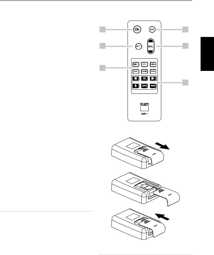
REMOTE CONTROL HANDSET AMP 1 (FIGURE 4)
The Remote Control handset handles all the key functions of the NAD C315BEE and has additional controls to remotely operate NAD CD machines. It will operate up to a distance of 16ft (5m). Alkaline batteries are recommended for maximum operating life. One CR2025 battery should be fitted in the battery compartment at the back of the Remote Control handset (see Figure 4).
Please refer to previous sections of the manual for a full description of individual functions.
When a command from the remote control is received, the Standby/ protection indicator will blink.
1POWER ON & OFF : The NAD C315BEE remote has a separate On and Off button. This can be particularly useful to keep components within a system “insync”: This way all components will switch to stand-by when Off is pressed or switch to operating mode when On is pressed, instead of some components switching On when the amplifier is switched
to Stand-by. (Note that the other components have to be capable of responding to the separate On and Off commands as well). Press the ON button to switch the unit from Stand-by to the operating mode; The Stand-by indicator (Fig. 1; No. 2) will turn from amber, to red, then to green. Press the OFF button to switch the unit to the Stand-by mode: The Stand-by indicator will light up amber.
2MUTE : Press the MUTE Button to temporarily switch off the sound to the speakers and headphones. Press MUTE again to restore sound. Mute does not affect recordings made using the Tape output but will affect the signal going to the Speakers.
Operation
3MASTER VOLUME : Press the MASTER VOLUME or
or buttons to respectively increase or decrease the loudness level. Release the button when the desired level is reached. The motorised Volume Control on the front panel will indicate the level set. The Master Volume buttons do not affect recordings made using the Tape outputs but will affect the signal going to the Speakers.
4INPUTS : The input selector buttons perform the same functions as the buttons labelled the same on the front panel.
5CD PLAYER CONTROL :
(for use with NAD CD-Player) 
 engages Pause
 engages Stop
 engages Play.
 engages reverse Skip

 engages forward Skip.
 engages CD drawer Open/Close; Press once to open the CD drawer then once again to close the CD drawer and start playback.
NOTES
The remote control handset supplied with the C315BEE is of a universal NAD type, designed to operate several NAD models.
Direct sunlight or very bright ambient lighting may affect the operating range and angle for the remote control handset.
REMOTE CONTROL HANDSET AMP 1 (FIGURE 4) |
|
1 |
1 |
2 |
3 |
4 |
|
|
5 |
ENGLISH
FRANÇAIS
NEDERLANDS DEUTSCH
ENSURE THE CORRECT
POLARITY IS OBSERVED.
WARNING
Do not expose the battery or remote to excessive heat, fire or alike.
ESPAÑOL
ITALIANO
РУССКИЙ
SVENSKA

ENGLISH
FRANÇAIS
ESPAÑOL NEDERLANDS DEUTSCH
ITALIANO
РУССКИЙ
SVENSKA
TROUBLESHOOTING
PROBLEM |
|
CAUSE |
|
SOLUTION |
|
|
|
|
|||
NO SOUND |
• Power AC lead unplugged or power not |
• Check if AC lead is plugged in and power |
|||
|
|
switched on |
|
switched on |
|
|
|
|
|||
|
• Mute on |
• Switch off Mute |
|||
|
|
|
|||
|
• Headphones inserted |
• Unplug the headphones |
|||
|
|
|
|
|
|
NO SOUND ONE CHANNEL |
• |
Balance control not centered |
• |
Center Balance control |
|
|
|
|
|||
|
• Speaker not properly connected or damaged |
• Check connections and speakers |
|||
|
|
|
|||
|
• Input lead disconnected or damaged |
• Check leads and connections |
|||
|
|
|
|
|
|
WEAK BASS / DIFFUSED STEREO IMAGE |
• |
Speakers wired out of phase |
• |
Check connections to all speakers in the |
|
|
|
|
|
system |
|
|
|
|
|
|
|
REMOTE CONTROL HANDSET NOT |
• |
Battery flat, or incorrectly inserted |
• |
Check or replace battery |
|
WORKING |
|
|
|
|
|
• |
IR transmitter or receiver windows obstructed |
• |
Remove obstruction |
||
|
|||||
|
|
|
|
||
|
• IR receiver in direct sun or very bright |
• |
Place unit away from direct sun, reduce |
||
|
|
ambient light |
|
amount of ambient light |
|
|
|
|
|
||
POWER/PROTECTION LED TURNS RED |
• |
Amplifier has overheated |
• Turn amplifier off, make sure ventilation |
||
DURING OPERATION |
|
|
|
slots on top and bottom of amplifier are not |
|
|
|
|
|
blocked. After amplifier has cooled down, |
|
|
|
|
|
turn back on. |
|
|
|
|
|
|
|

SPECIFICATIONS
Line level inputs (Disc, CD, Video, Aux, Tuner, Tape) measured at Speakers Output
Input impedance (R and C) |
50kΩ + 100pF |
Input sensitivity (ref. rated power) |
200mV |
Maximum input signal |
7V |
Line level outputs
Output impedance Tape Source Z + 600Ω
Tone controls
Treble |
|
±5dB at 10kHz |
Bass |
|
±8dB at 100Hz |
Continuous output power into 8Ω 2 |
|
40W (16dBW) |
Rated distortion (THD 20Hz - 20kHz) |
|
0.02% |
Clipping power (maximum continuous power per channel 4Ω and 8Ω) |
|
40W |
IHF Dynamic headroom |
8Ω |
45W, +16.5dB |
|
4Ω |
60W, +17.8dB |
IHF dynamic power (maximum short term power per channel) |
8Ω |
90W (19.5dBW) |
|
4Ω |
120W (20.8dBW) |
Damping factor (ref. 8Ω, 1kHz) |
|
>200 |
Voltage gain |
|
39dB |
Signal/noise ratio, A-weighted 1 |
ref. 1W |
95dB |
THD + Noise 3 |
|
<0.02% |
SMPTE IM 4 |
|
<0.02% |
IHF IM 5 |
|
<0.01% |
Headphone output impedance |
|
68Ω |
|
|
|
PHYSICAL SPECIFICATIONS |
|
|
Dimensions (W x H x D) 6 |
Net |
435 x 70 x 242mm |
|
Gross |
435 x 80 x 292mm |
Net weight |
|
5.25kg (11.5lb) |
Shipping weight |
|
6.5kg (14.3lb) |
1From CD input to speakers output, volume setting for 500mV in, 8Ω 1W out
2Minimum power per channel, 20Hz - 20kHz, both channels driven with no more than rated distortion.
3Total harmonic distortion, 20Hz - 20kHz from 250mW to rated output
4Intermodulation distortion, 60Hz - 7kHz, 4:1, from 250mW to rated output
5CCIF IM distortion, 19 + 20kHz rated output
6Gross dimensions include feet, volume knob and extended speaker terminals.
Specifications are subject to change without notice. For updated documentation and features please log onto www.nadelectronics.com for the latest information about your C315BEE.
ENGLISH
FRANÇAIS
ESPAÑOL NEDERLANDS DEUTSCH
ITALIANO
РУССКИЙ
SVENSKA
ENGLISH
FRANÇAIS
ESPAÑOL NEDERLANDS DEUTSCH
ITALIANO
РУССКИЙ
SVENSKA
CONSIGNES DE SECURITE IMPORTANTES
Conservez ces instructions afin de pouvoir vous en servir ultérieurement.Tenez compte de tous les avertissements et suivez toutes les instructions que vous trouverez sur le matériel audio.
1Lisez les instructions - Il est essentiel de lire toutes les consignes de sécurité avant de faire fonctionner le produit.
2Conservez les instructions - Les consignes de sécurité et les instructions d’utilisation doivent être conservées pour pouvoir les consulter ultérieurement.
3Tenez compte des Avertissements - Tous les Avertissements imprimés sur le produit et figurant dans les instructions d’utilisation doivent être respectés.
4Suivez les instructions - Toutes les instructions d’utilisation et de fonctionnement doivent être suivies.
5Nettoyage - Débranchez ce produit de la prise murale avant de procéder à son nettoyage. N’utilisez aucun nettoyant liquide ou aérosol. Servez-vous d’un chiffon humide pour effectuer le nettoyage.
6Fixations - N’utilisez aucune fixation non recommandée par le fabricant du produit, car cela peut entraîner des risques.
7Eau et humidité - N’utilisez pas ce produit près de l’eau, par exemple près d’une baignoire, d’un lavabo, d’un évier ou d’un bac à lessive. Ne l’utilisez pas non plus dans une cave humide, près d’une piscine ou dans un endroit semblable.
8Accessoires - Ne mettez jamais cet appareil sur un chariot, un support, un trépied, une console ou une table instables. L’appareil risquerait de tomber, provoquant des blessures graves chez un enfant ou un adulte et pourrait lui-même subir de sérieux dommages. Utilisez exclusivement un chariot, un support, un trépied, une console ou une table préconisés par le fabricant ou vendus avec l’appareil. Toute fixation du produit doit être réalisée conformément aux instructions du fabricant, et à l’aide d’un accessoire de fixation préconisé par le fabricant.
9Un ensemble appareil et chariot doit toujours être déplacé avec
précaution. Les arrêts brusques, les efforts excessifs et les sols accidentés risquent de renverser le chariot et l’appareil.
10Ventilation - Le boîtier de l’appareil comporte des fentes d’aération évitant au produit de surchauffer et lui permettant de fonctionner de façon fiable. Ces fentes ne doivent donc jamais être obstruées ou recouvertes. Les fentes ne doivent jamais être obstruées en posant l’appareil sur un lit, un canapé, un tapis ou toute autre surface molle similaire. Ce produit ne doit pas être placé dans un ensemble encastré, comme par exemple une bibliothèque vitrée ou un rack, à moins de prévoir une ventilation adéquate ou de respecter les instructions du fabricant.
11Sources d’alimentation - Ce produit doit obligatoirement être alimenté par une source du type indiqué sur l’étiquette. Si vous avez un doute concernant le type d’alimentation secteur utilisé dans votre domicile, consultez votre revendeur ou le fournisseur local d’électricité. La principale méthode à utiliser pour isoler
l’amplificateur de l’alimentation secteur est de débrancher la prise secteur. Assurezvous que la prise secteur reste accessible à tout moment. Débranchez le cordon secteur de la prise murale si l’appareil ne va pas être utilisé pendant plusieurs mois.
12Mise à la terre ou Polarité - Il se peut que cet appareil soit équipé d’une prise secteur alternatif avec système de détrompage (fiche comportant deux broches plates, l’une plus large que l’autre). Cette fiche ne se branche sur la prise murale que dans un sens. Il s’agit d’un dispositif de sécurité. Si la fiche n’entre pas complètement dans la prise, essayez de la brancher dans l’autre sens. Si elle n’entre toujours pas, appelez votre électricien et demandez-lui de remplacer votre prise murale obsolète. Ne bricolez pas le dispositif de sécurité de la prise avec détrompage.
13Protection du câble d’alimentation - Les câbles d’alimentation ne doivent pas passer dans des endroits où ils risquent d’être piétinés ou pincés par des articles posés dessus ou à côté. Faites particulièrement attention aux câbles au niveau des prises, des connecteurs de commodité à l’arrière d’autres appareils, et à leur point de sortie de cet appareil.
14Mise à la terre d’une Antenne Extérieure - Si l’appareil est relié à une antenne extérieure ou à un réseau de câbles extérieurs, veillez à ce que l’antenne ou le réseau de câbles soit mis à la terre afin d’assurer la même protection contre les pics de tension et les charges liées à l’accumulation d’électricité statique. L’Article 810 du National Electrical Code (NEC), ANSI/NFPA 70, contient des informations concernant la mise à la terre correcte du mât et de la structure porteuse, la mise à la terre du câble d’amenée sur un dispositif de décharge d’antenne, le calibre des câbles de mise à la terre, l’emplacement du dispositif de décharge d’antenne, le branchement aux électrodes de mise à la terre et les exigences concernant les électrodes de mise à la terre.
NOTE À L’ATTENTION DE L’INSTALLATEUR CATV
Ce rappel a pour but d’attirer l’attention de l’installateur du système d’antenne collective sur la Section 820 40 du National Electrical Code (NEC), qui donne des informations concernant la mise à la terre correcte et qui spécifie, en particulier, que la terre du câble doit être reliée au système de mise à la terre du bâtiment et ce le plus près possible du point d’entrée du câble.
15Foudre - Afin d’assurer une meilleure protection de cet appareil pendant les orages, ou lorsqu’il reste inutilisé et sans surveillance pendant de longues
périodes, débranchez la prise murale et déconnectez l’antenne ou le système de câbles. Cela évitera toute détérioration de l’appareil par la foudre ou par les surtensions de secteur.
16Câbles haute tension - Un système d’antenne extérieure ne doit pas être placé près de lignes haute tension aériennes ou d’autres circuits d’éclairage ou de puissance électriques. Lorsque vous installez un système d’antenne extérieure, faites très attention de ne pas toucher de telles lignes haute tension ou de tels circuits, car tout contact pourrait être mortel.
17Surcharge électrique - Ne surchargez pas les prises murales, les rallonges électriques ou les connecteurs de commodité des appareils, sous peine de provoquer des chocs électriques ou des risques d’incendie.
18Pénétration d’objets ou de liquides - N’insérez jamais d’objet de quelque type que ce soit par les ouvertures de l’appareil, car de tels objets risqueraient de toucher des tensions électriques dangereuses ou de court-circuiter des éléments pouvant provoquer un choc électrique ou un incendie. Ne renversez jamais de liquide sur l’appareil.
ATTENTION DANGER : L’appareil ne doit pas être exposé au ruissellement de liquides ou aux l’éclaboussures par ceuxci ; ne placez jamais de récipient (vase, etc ...) contenant un
liquide sur l’appareil. Comme pour tout appareil électronique, faites attention de ne pas renverser de liquide sur une partie quelconque du système. Les liquides peuvent provoquer une panne et/ou représenter un risque d’incendie.
19 Détériorations nécessitant une intervention en Service Après Vente - Dans les cas suivants, débranchez cet appareil de la prise murale et confiez la réparation à un personnel de service après vente qualifié :
a)Si le câble secteur ou sa prise sont endommagés.
b)Si un liquide a été renversé sur l’appareil ou si des corps étrangers sont tombés à l’intérieur.
c)Si l’appareil a été exposé à la pluie ou à de l’eau.
d)Si le produit ne fonctionne pas normalement lorsque vous suivez les instructions d’utilisation. Ne réglez que les commandes décrites dans les instructions d’utilisation, car tout réglage incorrect des autres commandes risque de provoquer des détériorations nécessitant une intervention importante par un technicien qualifié pour remettre l’appareil en état de fonctionnement normal.
e)Si l’appareil est tombé ou a été endommagé d’une manière quelconque.
f)Si les performances de l’appareil changent sensiblement, cela indique qu’une intervention en service après vente est nécessaire.
10
CONSIGNES DE SECURITE IMPORTANTES
20Pièces de rechange - Lorsque des pièces de rechange sont nécessaires, veillez à ce que le technicien utilise des pièces de rechange préconisées par le fabricant ou ayant des caractéristiques identiques. Toute pièce non autorisée risque de provoquer un incendie, un choc électrique ou d’autres dangers.
21Contrôle de sécurité - Après toute intervention d’entretien ou de réparation sur cet appareil, demandez au technicien d’effectuer des contrôles de sécurité afin de s’assurer que le produit est en bon état de fonctionnement.
22Fixation au mur ou au plafond - L’appareil ne doit être fixé au mur ou au plafond que suivant les recommandations du fabricant.
ATTENTION DANGER
POUR ÉVITER TOUT RISQUE D’INCENDIE OU DE CHOC ÉLECTRIQUE, N’EXPOSEZ JAMAIS CET APPAREIL A LA PLUIE OU A L’HUMIDITÉ. LE SYMBOLE DE L’ÉCLAIR AVEC UNE FLÈCHE À SON EXTRÉMITÉ, DANS UN TRIANGLE ÉQUILATÉRAL, A POUR BUT D’AVERTIR L’UTILISATEUR DE LA PRÉSENCE D’UNE “TENSION ÉLECTRIQUE DANGEREUSE”À L’INTÉRIEUR DE L’ENCEINTE DE L’APPAREIL, QUI PEUT ÊTRE SUFFISAMMENT PUISSANTE POUR CONSTITUER UN RISQUE DE CHOC ÉLECTRIQUE POUR LES PERSONNES.
LE POINT D’EXCLAMATION DANS UN TRIANGLE ÉQUILATÉRAL A POUR BUT D’AVERTIR L’UTILISATEUR QUE LA DOCUMENTATION LIVRÉE AVEC L’APPAREIL CONTIENT DES INSTRUCTIONS IMPORTANTES CONCERNANT L’UTILISATION ET L’ENTRETIEN.
ATTENTION |
En cas de changement ou de modification dont la conformité n’aura pas été expressément approuvé(e) par NAD Electronics, le droit de l’utilisateur de faire fonctionner l’appareil risque d’être annulé.
MISE EN GARDE CONCERNANT L’EMPLACEMENT
Afin d’assurer une ventilation correcte, faites attention de laisser un espace dégagé autour de l’appareil. Les dimensions de cet espace (mesurées par rapport à l’encombrement maximum l’appareil, y compris les parties saillantes) doivent être au moins égales aux valeurs indiquées ci-dessous :
Panneaux Gauche et Droit : 10 cm Panneau arrière : 10 cm
Panneau supérieur : 50 cm
INFORMATIONS IMPORTANTES POUR LES CLIENTS AU ROYAUME UNI
NE COUPEZ PAS la prise secteur moulée sur le câble d’alimentation de cet appareil. Si la prise secteur de l’appareil ne convient pas aux prises murales de votre domicile, ou si le câble d’alimentation est
trop court pour atteindre une prise murale, achetez une rallonge homologuée ou consultez votre revendeur. Si la prise a secteur moulée a néanmoins été coupée du câble d’alimentation, ÔTEZ LE FUSIBLE et jetez immédiatement la prise, afin d’éviter tout risque de choc électrique en cas de branchement par inadvertance sur une prise murale. Si ce produit n’est pas livré avec une prise secteur, ou alors s’il s’avère nécessaire d’en monter une, suivez les instructions données ci-dessous :
IMPORTANT
NE BRANCHEZ AUCUN fil sur la plus grosse fiche, repérée par la lettre “E” ou par le symbole de sécurité représentant la terre, ou de couleur VERTE ou VERT ET JAUNE.
Les couleurs des conducteurs dans le câble secteur de ce produit sont conformes au code suivant :
BLEU - NEUTRE MARRON - PHASE
Dans la mesure où ces couleurs ne correspondront peut-être pas aux couleurs des fiches dans votre prise secteur à monter, procédez comme indiqué ci-dessous : Le fil BLEU doit être relié à la fiche repérée par la lettre “N” ou de couleur noire.
Le fil MARRON doit être relié à la fiche repérée par la lettre “L” ou de couleur rouge. Lorsque vous remplacez le fusible, utilisez exclusivement un fusible homologué de calibre et de type corrects ; faites attention de bien remettre le cache fusible.
EN CAS DE DOUTE, FAITES APPEL A UN ELECTRICIEN COMPETANT
Ce produit a été fabriqué de manière à être conforme aux exigences concernant les interférence radio des DIRECTIVES CEE 89/68/EEC et 2006/95/EEC.
NOTES CONCERNANT LA PROTECTION DE L’ENVIRONNEMENT
À la fin de sa vie utile, il ne faut pas jeter ce produit avec les déchets ménagers. Il faut l’apporter à un point de collecte pour le recyclage des matériels
électriques et électroniques. Le symbole figurant sur le produit, dans le

 manuel de l’utilisateur et sur l’emballage vous indique cette obligation. Les matériaux sont réutilisables conformément aux marquages qui figurent dessus. Grâce au recyclage des matières premières, ou aux autres formes de recyclage de
produits anciens, vous apportez une contribution importante à la protection de notre environnement.
Votre administration locale pourra vous indiquer où se trouve le point de collecte de déchets concerné.
N° de Modèle : ________________________
N° de Série :_________________
ENGLISH
FRANÇAIS
ESPAÑOL NEDERLANDS DEUTSCH
ITALIANO
РУССКИЙ
SVENSKA
11
ENGLISH
FRANÇAIS
ESPAÑOL NEDERLANDS DEUTSCH
ITALIANO
РУССКИЙ
SVENSKA
PRÉPARATION |
|
|
|
|
|
|
|
|
|
|
|
|
COMMANDES SUR LA FACE PARLANTE (FIGURE 1) |
|
|
|
|
|
|
||||||
1 |
2 |
|
|
|
|
|
|
|
7 |
|
|
|
|
Stereo Integrated Amplifier C 315BEE |
|
|
|
|
|
|
|
|
VOLUME |
||
|
|
|
|
|
|
|
|
|
|
|||
|
|
|
|
|
|
|
|
BASS |
TONE |
TREBLE |
BALANCE |
|
|
|
|
|
|
|
|
|
DEFEAT |
|
|||
|
PHONES |
TAPE |
TUNER |
AUX |
VIDEO |
CD |
DISC |
MP |
|
|
|
|
© NAD C 315BEE |
|
|
|
|
|
|
|
|
|
|
|
|
|
3 |
|
|
|
4 |
|
|
5 |
6 |
|
8 |
9 |
BRANCHEMENTS SUR LE PANNEAU ARRIERE (FIGURE 2)
7 |
8 |
1 |
2 |
3 |
4 |
5 |
6 |
9 |
FILS NUS ET BORNES A BROCHES (FIGURE 3)
Attention Danger
Les bornes repérées par ce symbole sont sous tension secteur et sont dangereux. Le câblage électrique relié à ces bornes nécessite une installation par une personne formée, ou alors l’utilisation de fils ou de cordons spécialement conçus et fabriqués.
NAD est une marque déposée de NAD Electronics International, division de Lenbrook Industries Limited. 2007, NAD Electronics International, division de Lenbrook Industries Limited
12

FONCTIONNEMENT
NOTES CONCERNANT L’INSTALLATION
Posez votre NAD C315BEE sur une surface, stable, plane et horizontale. Évitez les rayons directs du soleil et les sources de chaleur et d’humidité. Assurez une ventilation adéquate. Ne posez pas l’appareil sur une surface molle (moquette, par exemple). Ne le placez pas dans un endroit confiné (sur une étagère de bibliothèque ou derrière des portes vitrées), où le flux d’air à travers les ouïes de ventilation risque d’être entravé. Vérifiez que l’appareil est hors tension avant de réaliser des connexions quelconques. Pour vous faciliter la tâche, les prises RCA de votre NAD C315BEE sont codées couleur. Rouge pour l’audio droite, blanc pour l’audio gauche. N’utilisez que des câbles et des connecteurs de très bonne qualité, de manière à obtenir un branchement dont la fiabilité est parfaite et les performances optimales. Vérifiez que les câbles et les connecteurs ne présentent aucune détérioration, et que tous les connecteurs sont bien enfoncés jusqu’en butée.
Pour obtenir les meilleures performances, utilisez des câbles de hautparleurs d’une épaisseur égale ou supérieure au calibre 16 (1,5 mm) ou plus. Si l’appareil doit rester inutilisé pendant un certain temps, débranchez le cordon d’alimentation de la prise de secteur murale.
Si de l’eau pénètre à l’intérieur de votre NAD C315BEE, coupez l’alimentation de l’appareil et retirez la fiche de la prise secteur. Faites contrôler l’appareil par un technicien de service après-vente qualifié, avant toute tentative de remise en service.
NE RETIREZ PAS LE COUVERCLE. A L’INTERIEUR, IL N’Y A AUCUN ELEMENT SUR LEQUEL L’UTILISATEUR PEUT INTERVENIR.
Utilisez un chiffon doux sec et propre pour nettoyer l’appareil. Si nécessaire, humectez le chiffon avec un peu d’eau savonneuse. N’utilisez jamais une solution contenant du benzol ou un quelconque autre agent volatile.
MISE EN MARCHE RAPIDE
1Branchez les haut-parleurs sur les bornes“Haut-parleur”[Speaker] à l’arrière et branchez les sources aux prises d’entrée appropriées à l’arrière.
2Branchez le cordon d’alimentation secteur.
3Mettez le bouton d’ALIMENTATION [POWER] du panneau arrière sur MARCHE [ON] pour mettre le C315BEE en veille.
4Appuyez sur le bouton Veille [Standby] de la face parlante pour mettre le NAD C315BEE en marche.
5Appuyez sur le sélecteur d’entrée correspondant à la source que vous souhaitez entendre.
COMMANDES SUR LA FACE PARLANTE (FIGURE 1)
1Bouton Veille [Standby] : Le bouton Veille [Standby] met le C315BEE en marche et en mode veille. Ce bouton ne fonctionne que lorsque la LED Marche/Veille/Protection [Power/Standby/Protection] est soit orange pour indiquer l’état de veille, soit verte pour indiquer l’état alimenté.
2LED Alimentation /Veille / Protection [Power/Standby/Protection]:
Lorsque vous mettez l’appareil sous tension, la LED s’allume en rouge pendant quelques secondes avant la désactivation du circuit de protection. La LED passe alors au vert pour indiquer le fonctionnement normal. En cas d’importante surcharge de l’amplificateur, comme par exemple l’utilisation d’un haut-parleur d’impédance très faible, de court-circuit, etc ..., les circuits de protection de l’amplificateur entrent en jeu ; cet état est indiqué par le passage au rouge du LED, et par la coupure du son. Dans un cas comme celui-ci, mettez l’amplificateur hors tension grâce à l’interrupteur d’ALIMENTATION [POWER] du panneau arrière, attendez qu’il refroidisse et vérifiez le branchement des haut-parleurs ; vérifiez aussi que l’impédance
globale des haut-parleurs ne passe pas en dessous de 4 ohms. Une fois que vous aurez éliminé la cause de l’activation des circuits de protection, remettez l’appareil en MARCHE [ON] à l’aide du bouton d’ALIMENTATION [POWER] puis du bouton de Veille [Standby] pour reprendre le fonctionnement normal.
3Prise casque : Une prise stéréo pour fiche à jack de 1/4” est prévue pour l’écoute avec casque et convient aux casques conventionnels à impédance quelconque. Le fait de brancher la fiche jack d’un casque dans cette prise coupe automatiquement le son des haut-parleurs. Les commandes de volume sonore, de tonalité et de balance agissent aussi sur l’écoute sur casque. Utilisez un adaptateur approprié pour brancher des casques équipés d’un autre type de connecteur, tel qu’un jack stéréophonique de 3,5 mm de type “baladeur stéréo”.
NOTES CONCERNANT LA SECURITE
•Vérifiez que la commande de volume sonore est au minimum (butée anti-horaire) avant de brancher ou de débrancher le casque. L’écoute à des niveaux sonores élevés peut entraîner des dommages auditifs permanents.
•Une pression sonore excessive produite par des écouteurs ou par un casque peut entraîner la perte de l’ouie.
4Sélecteurs d’entrées : Ces boutons permettent de sélectionner l’entrée active du NAD C315BEE ainsi que le signal envoyé aux haut-parleurs et aux sorties Magnétophone. Les boutons sur la télécommande sont identiques à ces boutons. Une LED verte, à l’aplomb de chaque bouton, indique l’entrée active. MAGNÉTOPHONE [TAPE] Sélectionne la sortie d’un magnétophone lors de la lecture de bandes d’enregistrements réalisés via les prises Magnétophone [Tape].
TUNER Sélectionne, comme entrée active, le tuner (ou une source de niveau ligne) branché aux prises Tuner.
AUX Sélectionne, comme entrée active, une source de niveau ligne branchée aux prises AUX.
VIDEO Sélectionne, comme entrée active, le magnétoscope (ou un téléviseur stéréo/décodeur satellite/récepteur de télédistribution) connecté aux prises VIDÉO.
CD Sélectionne, comme entrée active, le lecteur CD (ou une source de niveau ligne) branchée aux prises CD.
DISC/MP (Disque / Lecteur de Media) Sélectionne, comme entrée active, une source de niveau ligne branchée aux prises DISQUE [DISC]. Lorsque vous insérez une fiche stéréo de 3,5 mm stéréo dans la prise MP, l’indicateur au dessus de la prise s’allume et la source DISC de niveau
ligne est déconnectée. Il est conseillé de couper le volume sonore à l’aide de la fonction Muet, ou alors de passer sur une autre entrée, avant de brancher/débrancher le câble de Lecteur de Médias extérieur.
5Récepteur infrarouge de télécommandes : Le capteur infrarouge, situé derrière cette fenêtre circulaire, reçoit les commandes de la télécommande. L’espace entre la télécommande et le récepteur doit être dégagé de tout obstacle, sinon la télécommande pourrait refuser de fonctionner.
NOTES
Les rayons de soleil directs ou un éclairage d’ambiance très lumineux peuvent avoir une incidence sur la distance et l’angle de fonctionnement de la télécommande.
La télécommande livrée avec le C315BEE est de type universel NAD et est conçue pour commander plusieurs modèles NAD.
6Commandes de Tonalité : Le NAD C315BEE est équipé de commandes de GRAVES [BASS] ET d’AIGUS [TREBLE], qui permettent de régler la tonalité globale de votre chaîne.
La position médiane (12 heures) correspond à une courbe plate, sans amplification ni atténuation; un léger déclic est ressenti dans le mouvement du bouton à cet endroit. Tournez le bouton en sens horaire pour amplifier les Graves ou les Aigus. Tournez le bouton en
sens anti-horaire pour atténuer les Graves ou les Aigus. Les commandes de Tonalité n’affectent pas les enregistrements faits au moyen des Sorties “Magnétophone” [TAPE] mais agissent toutefois sur le signal allant vers les haut-parleurs.
ENGLISH
FRANÇAIS
ESPAÑOL NEDERLANDS DEUTSCH
ITALIANO
РУССКИЙ
SVENSKA
13

ENGLISH
FRANÇAIS
ESPAÑOL NEDERLANDS DEUTSCH
ITALIANO
РУССКИЙ
SVENSKA
FONCTIONNEMENT
7Tonalité Neutre [Tone defeat] : L’interrupteur de TONALITÉ NEUTRE [TONE DEFEAT] contourne la section de commande de la tonalité du NAD C315BEE. Si l’on n’utilise pas les commandes de tonalité, c’est à dire si elles restent toujours en position médiane (12 heures), il est conseillé de mettre les circuits de réglage de la tonalité complètement hors circuit grâce à ce bouton-interrupteur. Si le bouton n’est pas enfoncé, les circuits de tonalité sont actifs; le fait d’enfoncer le bouton“TONALITÉ NEUTRE” [TONE DEFEAT] contourne les circuits de réglage de la tonalité.
8Balance : La commande BALANCE règle les niveaux relatifs des hautparleurs gauche et droit. La position médiane (12 heures) assure un niveau égal pour les voies gauche et droite. Un léger déclic est ressenti dans le mouvement du bouton à cet endroit.
En tournant le bouton en sens horaire, vous déportez l’équilibre vers la droite. En tournant le bouton en sens anti-horaire, vous déportez l’équilibre vers la gauche. La commande de BALANCE n’affecte pas les enregistrements faits au moyen des Sorties “Magnétophone” [TAPE] mais agit toutefois sur le signal allant vers les haut-parleurs.
9Volume : La commande de VOLUME sonore règle le volume global des signaux envoyés aux haut-parleurs. Elle est motorisée et peut être réglée à l’aide de la télécommande. La commande de VOLUME n’affecte pas les enregistrements faits au moyen des Sorties “Magnétophone” [TAPE] mais agit toutefois sur le signal allant vers les haut-parleurs.
Sur la télécommande, appuyez sur le bouton “SILENCIEUX” [MUTE] pour couper provisoirement le son des haut-parleurs et du casque. Le mode Silencieux est indiqué par le clignotement de la LED de l’entrée active.
Réappuyez sur le bouton SILENCIEUX [MUTE] pour remettre le son. La commande Muet n’affecte pas les enregistrements faits au moyen des Sorties “Magnétophone” [TAPE] mais agit toutefois sur le signal allant vers les haut-parleurs.
BRANCHEMENTS SUR LE PANNEAU ARRIERE (FIGURE 2)
1Entrée Disc : Entrée pour les signaux d’entrée supplémentaires de niveau ligne, tels qu’un lecteur CD, un lecteur Mini-Disc ou le signal de sortie provenant d’un amplificateur de rehausseur pour tourne-disques. Utilisez un câble jumelé RCA vers RCA pour relier les prises de “Sortie Audio” gauche et droite de l’appareil audio auxiliaire à cette entrée.
NOTES
Lorsque vous insérez une fiche stéréo de 3,5 mm stéréo dans la prise MP, l’indicateur au dessus de la prise s’allume et la source DISC de niveau ligne est déconnectée.
Il est conseillé de couper le volume sonore à l’aide de la fonction Muet, ou alors de passer sur une autre entrée, avant de brancher/débrancher le câble de Lecteur de Médias extérieur.
2Entrée CD : Entrée pour un lecteur CD ou pour toute autre source de signal de niveau ligne. Utilisez un câble jumelé RCA vers RCA pour relier les prises de sortie audio gauche et droite du lecteur CD à cette entrée. Le NAD C315BEE n’accepte que les signaux analogiques de votre lecteur CD.
3Entrée Vidéo input : Entrée pour le signal audio provenant d’un magnétoscope stéréo (ou TV stéréo / Satellite / Récepteur de télédistribution) ou d’une autre source audio de niveau ligne. En utilisant les câbles jumelés RCA vers RCA, reliez les connecteurs de “Sortie Audio” gauche et droit de l’appareil à ces entrées. Nota : Il s’agit d’entrées audio uniquement.
4Entrée AUX : Entrée pour d’autres signaux de niveau ligne, comme un deuxième lecteur CD par exemple. Utilisez un câble jumelé RCA vers RCA pour relier les prises de “Sortie Audio” gauche et droite de l’appareil audio auxiliaire à cette entrée.
5EntréeTuner : Entrée pour un tuner ou pour toute autre source de signal de niveau ligne. Utilisez un câble jumelé RCA vers RCA pour relier les connecteurs de“Sortie Audio” gauche et droit de l’appareil à cette entrée.
6Entrée / Sortie Magnétophone [Tape] : Branchements pour enregistrement et lecture analogiques sur un magnétophone audio de type quelconque. En utilisant des câbles jumelés RCA vers RCA, reliez les prises de “Sortie Audio” gauche et droite du magnétophone aux prises d’ENTRÉE MAGNÉTOPHONE [TAPE IN] pour la lecture et
le contrôle d’enregistrement des bandes. Reliez les prises d’Entrée Audio gauche et droite du magnétophone aux prises de SORTIE MAGNÉTOPHONE 1 [TAPE OUT] pour l’enregistrement des bandes.
ENREGISTREMENT
Lorsqu’une source est sélectionnée, son signal est aussi envoyé directement à un quelconque magnétophone relié aux SORTIES “MAGNÉTOPHONE” [TAPE] pour l’enregistrement.
7Haut-parleurs [Speakers] : Connecteurs de haut-parleurs, pour haut-parleurs ayant une impédance de 4 ohms ou plus. Branchez le haut-parleur droit sur les bornes repérées “R+” et “R-”, en vous assurant que le “R+” soit relié à la borne “+” de votre haut-parleur et que “R-” soit relié à la borne “-” de votre haut-parleur. Branchez les bornes repérées “L+” et “L “ au haut-parleur gauche en procédant de la même manière. N’utilisez que du fil torsadé haute puissance (calibre 16 ; 1,5 mm ou plus) pour brancher les haut-parleurs à votre NAD C315BEE. On peut utiliser les bornes pour courants élevés comme bornes à visser pour les câbles comportant des cosses plates, des broches ou des fils nus.
FILS NUS ET BORNES A BROCHES (FIGURE 3)
Les fils nus et les broches s’insèrent dans le trou diamétral percé dans la tige de la borne. Desserrez la bague en plastique de la borne de haut-parleur jusqu’à ce que le trou dans la tige soit visible. Insérez la broche ou le fil nu dans le trou, puis fixez le câble en vissant la bague de la borne. Veillez à ce qu’aucun fil nu des câbles des haut-parleurs ne touche le panneau arrière ou une autre prise. Veillez à ce qu’il n’y ait que 1 cm (1/2”) de fil nu ou de broche et qu’il n’y ait aucun brin libre sur les fils des haut-parleurs.
8Câble d’alimentation secteur : Branchez ce cordon à une prise murale secteur. Veillez à ce que tous les branchements aient été faits avant de brancher le cordon au secteur.
9Interrupteur MARCHE/ARRÊT [POWER] : L’interrupteur MARCHE/ ARRÊT [POWER] fournit l’alimentation secteur principale du C315BEE.
Lorsque cet interrupteur est en position MARCHE [ON], le C315BEE est en mode Veille, ce qui est indiqué par la LED orange sur la face parlante. Si vous n’avez pas l’intention d’utiliser l’amplificateur pendant une longue période, mettez l’interrupteur MARCHE/ARRÊT [POWER] à la position ARRÊT [OFF].
COMBINE DE TELECOMMANDE AMP 1 (FIGURE 4)
La Télécommande reproduit toutes les fonctions clés du NAD C315BEE, et comporte aussi des commandes supplémentaires permettant de
télécommander les Lecteurs de CD NAD. Elle fonctionne depuis une distance pouvant aller jusqu’à 5 mètres. Il est conseillé d’utiliser des piles alcalines pour une longévité maximale. Une pile CR2025 doit être insérée dans le compartiment de pile à l’arrière du combiné Télécommande (Cf. Figure 4). Reportez-vous aux sections précédentes du manuel pour des descriptions détaillées des différentes fonctions. Lors de la réception d’une commande en provenance du combiné de télécommande, la lampe témoin “Veille / Protection” [Stand-by/Protection] clignote.
14
FONCTIONNEMENT
1MARCHE/ARRÊT [POWER ON & OFF] : La télécommande NAD C315BEE est dotée de boutons Marche [On] et Arrêt [Off] distincts. Ceci est particulièrement utile pour maintenir la synchronisation des appareils constituant la chaîne : De cette manière, tous les appareils passeront en mode Veille lorsque vous appuierez sur “Arrêt” [Off], ou passeront en mode Marche lorsque vous appuierez sur “On” [Marche], plutôt que de se mettre en Marche lorsque vous mettrez l’amplificateur en mode Veille. (A noter que les autres appareils doivent eux aussi être capables de répondre à des commandes de Marche / Arrêt distinctes). Appuyez sur la touche “Marche” [ON] pour faire passer l’appareil du mode Veille au mode de fonctionnement ; la lampe témoin Veille [Stand-by] (Fig. 1 ; N° 2) passera de l’orange au rouge, puis au vert. Appuyez sur la touche OFF pour mettre l’appareil en mode Veille : La lampe témoin de Veille passera à l’orange.
2MUET [MUTE] : Appuyez sur la touche MUET [MUTE] pour couper provisoirement l’émission du son vers les haut-parleurs et le casque. Réappuyez sur MUET [MUTE] pour rétablir le son. La commande Muet n’affecte pas les enregistrements faits au moyen de la Sortie “Magnétophone” [TAPE] mais agit toutefois sur le signal allant vers les Haut-parleurs.
3VOLUME GÉNÉRAL [MASTER VOLUME] : Appuyez sur les touches
 ou
ou du VOLUME GÉNÉRAL [MASTER VOLUME] pour augmenter ou diminuer le volume sonore, respectivement. Relâchez la touche dès que le niveau sonore souhaité a été atteint. La Commande de Volume motorisée sur la face parlante indiquera le niveau réglé. La commande de Volume Général [Master Volume] n’affecte pas les enregistrements faits au moyen des sorties “Magnétophone” [Tape] mais agissent toutefois sur le signal allant vers les haut-parleurs.
4ENTRÉES : Les touches de sélection des entrées ont les mêmes fonctions que les boutons repérés de façon identique sur la face parlante.
5COMMANDE DU LECTEUR DE CD : Boutons de COMMANDE DU LECTEUR CD (pour utilisation avec un Lecteur CD NAD).

 active la fonction Pause.
 active l’Arrêt.
 active le mode Lecture [Play].
 active le mode de saut en arrière.

 active le mode de saut en avant.
 provoque l’Ouverture / Fermeture du plateau de CD ; appuyez une fois pour ouvrir le plateau de CD et une deuxième fois pour refermer le tiroir et commencer la lecture.
NOTES
La télécommande livrée avec le C315BEE est de type universel NAD et est conçue pour commander plusieurs modèles NAD.
Les rayons de soleil directs ou un éclairage d’ambiance très lumineux peuvent avoir une incidence sur la distance et l’angle de fonctionnement de la télécommande.
COMBINE DE TELECOMMANDE AMP 1 (FIGURE 4) |
|
1 |
1 |
2 |
3 |
4 |
|
|
5 |
VÉRIFIEZ LA BONNE
ORIENTATION DES PILES.
ATTENTION
N’exposez pas la batterie ou la télécommande à une chaleur excessive, au feu ou similaire.
ENGLISH
FRANÇAIS
ESPAÑOL NEDERLANDS DEUTSCH
ITALIANO
РУССКИЙ
SVENSKA
15

ENGLISH
FRANÇAIS
ESPAÑOL NEDERLANDS DEUTSCH
ITALIANO
РУССКИЙ
SVENSKA
DEPANNAGE
PROBLEME |
|
CAUSE |
|
SOLUTION |
|
|
|
|
|
AUCUN SON |
• |
Câble secteur débranché, ou alimentation |
• Vérifiez si le cordon d’alimentation est |
|
|
|
coupée. |
|
branché et que la prise murale est sous |
|
|
|
|
tension |
|
|
|
|
|
|
• |
Fonction “Silencieux” [Mute] actif. |
• |
Désactivez la fonction “Silencieux” [Mute]. |
|
|
|
||
|
• Casque branché |
• Débranchez le casque |
||
|
|
|
||
PAS DE SON SUR UNE VOIE |
• La commande de Balance n’est pas au centre |
• Centrez la commande de Balance |
||
|
|
|
|
|
|
• |
Haut-parleur incorrectement branché ou |
• |
Vérifiez les branchements et les haut-parleurs. |
|
|
détérioré |
|
|
|
|
|
|
|
|
• |
Le câble d’entrée est débranché ou détérioré. |
• Vérifiez les câbles et les branchements. |
|
|
|
|
|
|
GRAVES FAIBLES / IMAGE STÉRÉO DIFFUSE |
• |
Haut-parleurs câblés en déphasé. |
• |
Vérifiez le branchement de tous les haut- |
|
|
|
|
parleurs de la chaîne. |
|
|
|
|
|
LA TÉLÉCOMMANDE NE FONCTIONNE PAS |
• |
Pile usée ou incorrectement insérée. |
• Vérifiez ou remplacez la pile. |
|
|
|
|
|
|
|
• |
Fenêtre d’émission ou de réception IR |
• |
Retirez les obstructions. |
|
|
obstruée. |
|
|
|
|
|
|
|
|
• |
Le récepteur IR se trouve en plein soleil ou |
• Éloignez l’appareil des rayons de soleil directs, |
|
|
|
sous un éclairage d’ambiance trop puissant |
|
réduisez la luminosité |
|
|
|
|
|
LA LED D’ALIMENTATION / PROTECTION |
• |
L’amplificateur a surchauffé |
• Mettez l’amplificateur hors tension et vérifiez |
|
PASSE AU ROUGE PENDANT L’UTILISATION |
|
|
|
que les fentes d’aération sur le dessus et le |
|
|
|
|
dessous de l’amplificateur sont dégagées de |
|
|
|
|
toute obstruction. Une fois que l’amplificateur |
|
|
|
|
aura refroidi, le remettre sous tension. |
|
|
|
|
|
16

CARACTERISTIQUES
Entrées de niveau Ligne (Disc, CD, Vidéo, Aux, Tuner, Magnétophone [Tape]) mesurées sur les Sorties Haut-parleurs
Impédance d’entrée (R et C) |
50 kΩ + 100 pF |
Sensibilité d’entrée (réf. puissance nominale) |
200 mV |
Signal d’entrée maximum |
7 V |
Sorties de niveau Ligne
Impédance de sortie Magnétophone Source Z + 600 Ω
Commandes de tonalité
Aigus |
|
± 5 dB à 10 kHz |
Graves |
|
± 8 dB à 100 Hz |
Puissance de sortie en continu, sur 8 Ω 2 |
|
40 Ω (16 dBW) |
Distorsion nominale (Distorsion Harmonique Totale 20 Hz - 20 kHz) |
0,02 % |
|
Puissance d’écrêtage (puissance maximum continue par voie |
4 Ω et 8 Ω) |
40 W |
Plage dynamique IHF |
8Ω |
45 W, +16,5 dB |
|
4Ω |
60 W, +17,8 dB |
Puissance dynamique IHF (puissance maxi. instantanée par voie) |
8Ω |
90 W (19,5 dBW) |
|
4Ω |
110 W (20,4 dBW) |
Facteur d’amortissement (réf. 8 Ω, 1 kHz) |
|
> 200 |
Gain de tension |
|
39 dB |
Rapport Signal / Bruit avec pondération A |
réf. 1 W |
95 dB |
THD + Bruit 3 |
|
< 0,02 % |
SMPTE IM 4 |
|
<0,02 % |
IHF IM 5 |
|
< 0,01 % |
Impédance de sortie casque |
|
68 Ω |
|
|
|
CARACTERISTIQUES PHYSIQUES |
|
|
Dimensions (L x H x P) 6 |
Dimensions nettes |
435 x 70 x 242 mm |
|
Encombrement |
435 x 80 x 292 mm |
Masse nette |
|
5.25kg |
Masse en condition d’expédition |
|
6.5kg |
1De l’entrée CD à la sortie des HP, réglage de volume sonore pour 500 mV en entrée, 8 Ω 1 W en sortie
2Puissance minimum par voie, 20 Hz - 20 kHz, les deux voies étant pilotées avec une distorsion inférieure oui égale à la valeur nominale.
3Distorsion harmonique totale , 20 Hz - 20 kHz, depuis 250 mW jusqu’à la puissance de sortie nominale
4Distorsion d’intermodulation, 60 Hz - 7 kHz, 4:1, depuis 250 mW jusqu’à la puissance de sortie nominale
5Distorsion CCIF IM, 19 + 20 kHz sortie nominale
6L’encombrement comprend les pieds, le bouton de volume sonore et les bornes pour haut-parleurs supplémentaires.
Les caractéristiques de ce matériel peuvent être modifiées sans préavis. Pour la documentation au dernier indice et les caractéristiques les plus récentes, veuillez vous connecter sur www.nadelectronics.com, où vous trouverez les dernières informations concernant votre C315BEE.
ENGLISH
FRANÇAIS
ESPAÑOL NEDERLANDS DEUTSCH
ITALIANO
РУССКИЙ
SVENSKA
17
ENGLISH
FRANÇAIS
ESPAÑOL NEDERLANDS DEUTSCH
ITALIANO
РУССКИЙ
SVENSKA
WICHTIGE SICHERHEITSHINWEISE
Sicherheitshinweise zum Nachschlagen aufbewahren. Alle auf den Audiogeräten angebrachten Warnund Sicherheitshinweise befolgen.
1Anleitungen lesen - Alle Sicherheitsund Betriebsanleitungen vor der Gerätebenutzung aufmerksam lesen.
2Anleitungen aufbewahren - Die Sicherheitsund Betriebsanleitungen zum späteren Nachschlagen aufbewahren.
3Warnungen beachten - Alle Warnhinweise am Gerät und in der Bedienungsanleitung befolgen.
4Anleitungen befolgen - Alle Anleitungen für Betrieb und Benutzung des Gerätes befolgen.
5Reinigung – Vor der Gerätereinigung den Netzstecker aus der Steckdose ziehen. Keine flüssigen Reinigungsmittel oder Spraydosen-Reiniger verwenden, sondern nur mit einem feuchten Tuch reinigen.
6Anschlüsse - Keine Anschlüsse verwenden, die vom Hersteller nicht empfohlen sind. Sie könnten zu Gefahren führen.
7Wasser und Feuchtigkeit - Verwenden Sie dieses Gerät nicht in der Nähe von Wasser, z. B. neben einer Badewanne, Waschschüssel, Spüle oder einem Wäschekessel, in einem nassen Keller oder neben Schwimmbecken u. ä.
8Zubehör - Stellen Sie dieses Gerät nicht auf unstabile Handwagen, Ständer, Stative, Konsolen oder Tische. Wenn das Gerät herunterfällt, könnten Kinder oder Erwachsene schwere Verletzungen davontragen, und das Gerät könnte schwer beschädigt werden. Verwenden Sie nur Handwagen, Ständer, Stative, Konsolen oder Tische, die vom Hersteller empfohlen oder mit dem Gerät zusammen verkauft worden sind. Jeder Geräteeinbau sollte nur in vom Hersteller empfohlenem Einbauzubehör und unter Beachtung der Herstelleranleitung erfolgen.
9Steht das Gerät auf einem Handwagen, sollte dieser vorsichtig
bewegt werden. Schnelles Anhalten, überhöhte Kraftanwendung und unebene Bodenflächen können dazu führen, daß der Handwagen mit dem Gerät umkippt.
10Schlitze und Gehäuseöffnungen dienen der Luftzirkulation, sollen einen zuverlässigen Betrieb sicherstellen und das Gerät dabei vor Überhitzung schützen. Diese Öffnungen dürfen nicht blockiert oder abgedeckt werden. Das Gerät darf daher niemals auf ein Bett, Sofa, einen Teppich oder ähnliche Oberflächen gestellt werden. Es kann nur dann in einer festen Installation wie einem Einbauschrank oder Rack untergebracht werden, wenn für eine ausreichende Lüftung gesorgt wird und die Herstellerhinweise dabei beachtet werden.
11Netzanschluß - Dieses Gerät darf nur an Spannungsquellen betrieben werden, die im Etikett auf dem Gerät angegeben sind. Wenn Sie nicht sicher sind, welche Spannungsversorgung Sie in Ihrem Hause haben, wenden Sie sich an Ihren Händler oder an das örtliche Elektrizitätswerk. Als erste Maßnahmen zum Trennen des Verstärkers vom Netz wird der Netzstecker aus der Steckdose gezogen. Stellen Sie daher sicher, daß der Netzstecker immer zugänglich ist. Wenn das Gerät für mehrere Monate nicht verwendet wird, das Netzkabel aus der Steckdose ziehen.
12Dieses Gerät ist mit einem gepolten Wechselstromstecker ausgerüstet (ein Stift ist breiter als der andere). Der Stecker paßt nur auf eine Art in die Steckdose. Dies ist eine Sicherheitsvorkehrung. Wenn Sie den Stecker nicht ganz in die Steckdose einstecken können, versuchen Sie es mit umgedrehtem Stecker noch einmal. Paßt der Stecker immer noch nicht, wenden Sie sich an Ihren Elektriker, um die veraltete Steckdose auszutauschen. Versuchen Sie nicht, diese Sicherheitsvorkehrung in irgendeiner Weise zu umgehen.
13Netzkabelschutz - Das Verlegen von Netzkabeln muß so erfolgen, daß Kabelquetschungen durch Darauftreten oder daraufliegende Gegenstände ausgeschlossen sind. Dabei sollte besonders auf die Leitung in Steckernähe, Mehrfachsteckdosen und am Geräteauslaß geachtet werden.
14Erdung der Außenantenne - Wird eine Außenantenne oder ein Kabelsystem an das Gerät angeschlossen, sicherstellen, daß die Antenne oder das Kabelsystem geerdet ist, um einen gewissen Schutz gegen Spannungsspitzen und statische Aufladungen zu bieten. Artikel 810 des National Electrical Code, ANSI/NFPA
70, enthält Informationen zur geeigneten Erdung des Antennenmastes und Trägergerüstes, zur Erdung der Leitung einer Antennen-Entladeeinheit, zur Größe des Erders, Position der Antennen-Entladeeinheit, zum Anschließen und zu den Anforderungen von Erdern.
HINWEIS FÜR INSTALLATEURE VON KABEL-TV-SYSTEMEN
Wir möchten die Installateure von Kabel-TV-Systemen auf den Abschnitt 820-40 des NEC aufmerksam machen, in dem Richtlinien für sachgemäße Erdung zu finden sind und
in dem insbesondere festgelegt ist, daß die Kabelerdung mit dem Erdungssystem des Gebäudes verbunden werden soll, und zwar so nahe wie möglich an der Kabeleinführung.
15 Blitz - Ziehen Sie zum besonderen Schutz bei Gewitter oder wenn das Gerät unbeaufsichtigt über längere Zeit nicht verwendet wird, den Netzstecker aus der Steckdose und das Antennenkabel aus der Antennenoder Kabelsteckdose. Dadurch wird das Gerät vor Blitzoder Überspannungsschäden geschützt.
16 Hochspannungsleitungen - Eine Außenantennenanlage sollte nicht in direkter Nachbarschaft von Hochspannungsleitungen oder anderen elektrischen
Lichtoder Netzleitungen, oder wo sie in solche Spannungsleitungen fallen kann, installiert werden. Bei der Installation eines Außenantennensystems muß äußerst vorsichtig vorgegangen werden, um Hochspannungsleitungen nicht zu berühren. Der Kontakt mit solchen Leitungen kann tödlich sein.
17 Überlastung - Wandsteckdosen, Verlängerungskabel oder integrierte Mehrfachsteckdosen dürfen nicht überlastet werden. Gefahr von elektrischem Schlag und Feuer.
18 Eindringen von Fremdkörpern und Flüssigkeiten - Niemals irgendwelche Fremdkörper durch die Gehäuseöffnungen in das Gerät stecken. Sie könnten Teile mit gefährlichen Spannungen berühren oder einen Kurzschluß auslösen, der ein Feuer verursachen oder zu einem Stromschlag führen könnte. Niemals Flüssigkeiten, welcher Art auch immer, auf das Gerät schütten.
ACHTUNG: Das Gerät darf keinen tropfenden oder spritzenden Flüssigkeiten ausgesetzt werden, und flüssigkeitsgefüllte Gegenstände wie z. B. Vasen dürfen nicht auf das Gerät gestellt werden. Wie bei allen elektronischen Geräten darauf achten, dass auf keine Teile des Gerätes Flüssigkeiten
verschüttet werden. Flüssigkeiten können Störungen und/oder Brandgefahr verursachen.
19 Ziehen Sie den Geräte - Netzstecker aus der Steckdose und lassen Sie von qualifizierten Fachkräften eine Reparatur durchführen, wenn:
a)das Netzkabel oder der Netzstecker beschädigt ist.
b)Flüssigkeit in das Gerät geschüttet worden ist oder Fremdkörper hineingefallen sind.
c)das Gerät Regen oder Wasser ausgesetzt worden ist.
d)das Gerät trotz Beachtung der Bedienungsanleitung nicht normal funktioniert. Betätigen Sie nur Einsteller, die in der Bedienungsanleitung erwähnt werden. Die fehlerhafte Einstellung anderer Einsteller kann zu Beschädigung führen und erfordert häufig den enormen Aufwand eines qualifizierten Technikers, um den normalen Geräte-Betriebszustand wiederherzustellen.
e)das Gerät heruntergefallen oder in irgendeiner Weise beschädigt worden ist.
f)wenn das Gerät auffallende Veränderungen in der Leistung aufweist. Dies ist meistens ein Anzeichen dafür, daß eine Reparatur oder Wartung notwendig ist.
18
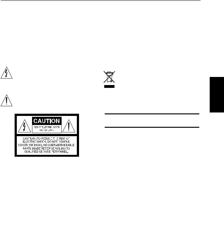
WICHTIGE SICHERHEITSHINWEISE
20Ersatzteile - Wenn Ersatzteile benötigt werden, stellen Sie sicher, daß der Servicetechniker Original-Ersatzteile vom Hersteller oder zumindest solche mit denselben Charakteristika wie die Originalteile verwendet hat. Nicht autorisierter Ersatz kann Feuer, elektrischen Schlag oder andere Gefahren verursachen.
21Sicherheitsüberprüfung - Bitten Sie den Servicetechniker nach allen Wartungen oder Reparaturen an diesem Gerät darum, eine
Sicherheitsüberprüfung durchzuführen und den einwandfreien Betriebszustand des Gerätes festzustellen.
22Wand oder Deckenmontage - Das Gerät darf an eine Wand oder Decke nur entsprechend der Herstellerhinweise montiert werden.
WARNUNG
UM DIE GEFAHR VON FEUER ODER STROMSCHLAG ZU VERHINDERN, DIESES GERÄT NICHT REGEN ODER FEUCHTIGKEIT AUSSETZEN. DAS BLITZSYMBOL MIT PFEIL IN EINEM GLEICHSEITIGEN DREIECK SOLL DEN BENUTZER VOR EINER NICHT ISOLIERTEN, FÜR DAS RISIKO EINES ELEKTRISCHEN SCHLAGES FÜR PERSONEN AUSREICHEND HOHEN
GEFÄHRLICHEN SPANNUNG IM INNERN DES GERÄTEGEHÄUSES WARNEN. DAS AUSRUFEZEICHEN IN EINEM GLEICHSEITIGEN DREIECK SOLL
DEN BENUTZER DARAUF AUFMERKSAM MACHEN, DASS DIE MIT DEM GERÄT GELIEFERTE DOKUMENTATION WICHTIGE BETRIEBSUND WARTUNGSHINWEISE ENTHÄLT.
Da diese Farben nicht mit den farblichen Markierungen der Klemmen in Ihrem Stecker übereinstimmen müssen, fahren Sie wie folgt fort:
Der BLAUE Draht muß mit der SCHWARZEN oder dem Buchstaben “N” gekennzeichneten Klemme verbunden werden.
Der BRAUNE Draht muß mit der ROTEN oder dem Buchstaben “L” gekennzeichneten Klemme verbunden werden.
Die Sicherung darf nur mit einem zugelassenen Typ mit denselben Nennwerten ersetzt werden. Sicherstellen, daß der Sicherungsdeckel wieder angebracht ist.
IM ZWEIFELSFALLE EINEN QUALIFIZIERTEN ELEKTRIKER HINZUZIEHEN.
Dieses Gerät wurde in Übereinstimmung mit den Anforderungen gegen Hochfrequenzstörungen der EEC RICHTLINIE 89/68/EEC und 2006/95/EEC hergestellt.
HINWEISE ZUM UMWELTSCHUTZ
Am Ende seiner Nutzungsdauer darf dieses Gerät nicht mit dem normalen Hausmüll entsorgt, sondern muß an einer Sammelstelle für Elektround
Elektronikschrott abgegeben werden. Dafür stehen die Symbole auf dem Gerät, in der Bedienungsanleitung und auf der Verpackung.
Die Materialien können entsprechend ihrer Kennzeichnung wiederverwendet werden. Durch Wiederverwendung, Recycling von Rohstoffen oder anderen Arten von Altgeräte-Recycling leisten Sie einen wichtigen Beitrag zum Schutz unserer Umwelt. Weitere Informationen über Ihre zuständige Abfallbeseitungsstelle erhalten Sie bei Ihrer örtlichen Verwaltung.
Modellnr. :________________________
Seriennr. :_________________
ENGLISH
FRANÇAIS
NEDERLANDS DEUTSCH
ACHTUNG
Werden Änderungen an diesem Gerät durchgeführt, die von NAD Electronics nicht ausdrücklich genehmigt sind, kann der Besitzer die Berechtigung zur Gerätebenutzung verlieren.
HINWEIS ZUR AUFSTELLUNG
Um eine ausreichende Lüftung zu gewährleisten, stellen Sie sicher, daß um das Gerät herum genügend Platz vorhanden ist (gemessen von den Außenabmessungen und evtl. hervorstehenden Teilen). Mindestabstände:
Linke und rechte Seite: 10 cm Rückwand: 10 cm Gehäusedeckel: 50 cm
WICHTIGE HINWEISE FÜR KUNDEN IN GROSSBRITANNIEN
Den Netzstecker dieses Gerätes NICHT abschneiden. Wenn der Netzstecker in keine Steckdose in Ihrem Räumen passt, oder das Netzkabel zu kurz für die vorhandenen Steckdosen ist, besorgen Sie
sich ein geeignetes und sicheres Verlängerungs¬kabel oder wenden Sie sich an Ihren Händler. Falls der Netzstecker bereits abgeschnitten ist, die SICHERUNG ENTFERNEN und den STECKER sofort vernichten, um die Gefahr eines möglichen Stromschlages durch versehentliches Einstecken in spannungsführende Steckdosen zu verhindern. Wurde dieses Gerät nicht mit einem Netzstecker geliefert, oder muß erst noch ein Stecker angeschlossen werden, folgen Sie der untenstehenden Anleitung:
WICHTIG
Schließen Sie KEINE Leitung am längeren Stift an, der mit dem Buchstaben “E”, dem Schutzerde-Symbol, der Farbe GRÜN oder GRÜNGELB gekennzeichnet ist.
Die Drähte im Netzkabel dieses Geräts sind entsprechend dem folgenden Farbcode gekennzeichnet:
BLAU - NEUTRAL
BRAUN - PHASE
ESPAÑOL
ITALIANO
РУССКИЙ
SVENSKA
19
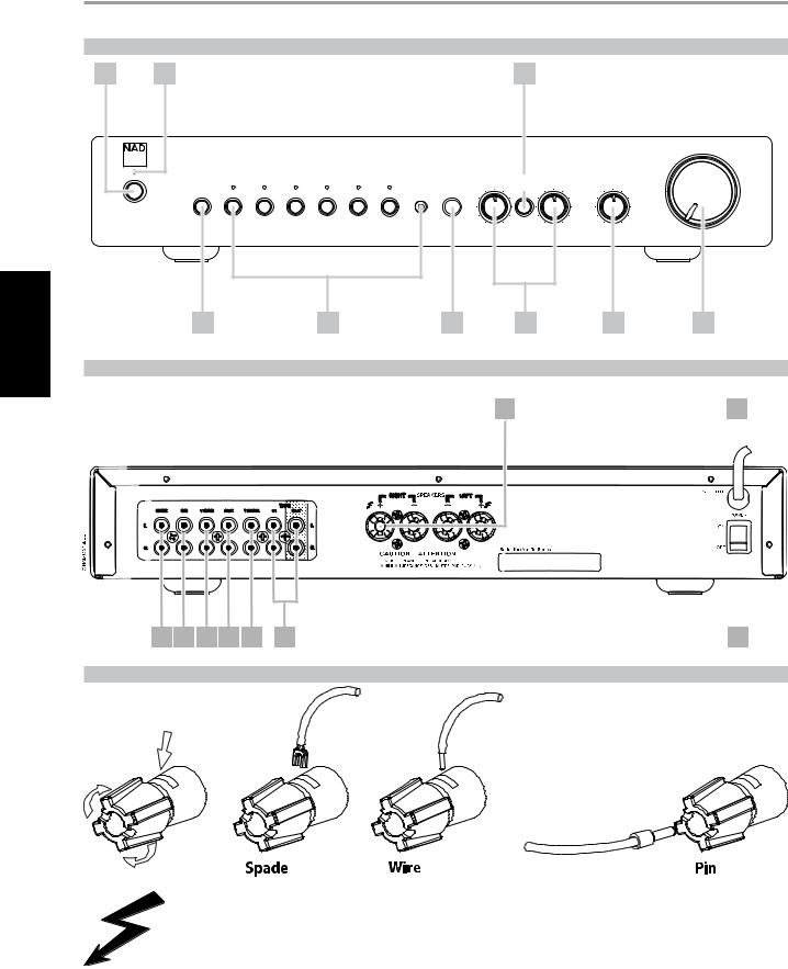
ENGLISH
FRANÇAIS
ESPAÑOL NEDERLANDS DEUTSCH
ITALIANO
РУССКИЙ
SVENSKA
VORBEREITUNG |
|
|
|
|
|
|
|
|
|
|
|
|
FRONTPLATTENELEMENTE (Abb. 1) |
|
|
|
|
|
|
|
|
||||
1 |
2 |
|
|
|
|
|
|
|
7 |
|
|
|
|
Stereo Integrated Amplifier C 315BEE |
|
|
|
|
|
|
|
|
VOLUME |
||
|
|
|
|
|
|
|
|
|
|
|||
|
|
|
|
|
|
|
|
BASS |
TONE |
TREBLE |
BALANCE |
|
|
|
|
|
|
|
|
|
DEFEAT |
|
|||
|
PHONES |
TAPE |
TUNER |
AUX |
VIDEO |
CD |
DISC |
MP |
|
|
|
|
© NAD C 315BEE |
|
|
|
|
|
|
|
|
|
|
|
|
|
3 |
|
|
|
4 |
|
|
5 |
6 |
|
8 |
9 |
RÜCKWANDANSCHLÜSSE (Abb. 2)
7 |
8 |
1 |
2 |
3 |
4 |
5 |
6 |
9 |
BLANKE DRÄHTE UND ENDHÜLSEN (ABB. 3)
Achtung
Die mit diesem Symbol markierten Kontakte sind gefährlich, wenn Sie stromführend sind. Eine externe Verkabelung zu diesen Kontakten muß von einer Fachkraft ausgeführt oder es müssen konfektionierte Leitungen oder Kabel verwendet werden.
NAD ist ein Warenzeichen von NAD Electronics International, einem Unternehmensbereich von Lenbrook Industries Limited Copyright 2007, NAD Electronics International, ein Unternehmensbereich von Lenbrook Industries Limited
20
 Loading...