


 Loading...

 ® C 368
Hybrid Digital DAC Amplifier
ENGLISH
Owner’s Manual
ENGLISH
IMPORTANT SAFETY INSTRUCTIONS
1.Read instructions - All the safety and operating instructions should be read before the product is operated.
2.Retain instructions - The safety and operating instructions should be retained for future reference.
3.Heed Warnings - All warnings on the product and in the operating instructions should be adhered to.
4.Follow Instructions - All operating and use instructions should be followed.
5.Cleaning - Unplug this product from the wall outlet before cleaning. Do not use liquid cleaners or aerosol cleaners. Use a damp cloth for cleaning.
6.Attachments - Do not use attachments not recommended by the product manufacturer as they may cause hazards.
7.Water and Moisture - Do not use this product near water-for example, near a bath tub, wash bowl, kitchen sink, or laundry tub; in a wet basement; or near a swimming pool; and the like.
8.Accessories - Do not place this product on an unstable cart, stand, tripod, bracket, or table. The product may fall, causing serious injury to a child or adult and serious damage to the product. Use only with a cart, stand, tripod, bracket, or table recommended by the manufacturer, or sold with the product. Any mounting of the product should follow the manufacturer’s instructions, and should use a mounting accessory recommended by the manufacturer.
9.Cart - A product and cart combination should be moved with care.
Quick stops, excessive force, and uneven surfaces may cause the product and cart combination to overturn.
10.Ventilation - Slots and openings in the cabinet are provided for ventilation to ensure reliable operation of the product and to protect it from overheating.
These openings must not be blocked or covered. The openings should never be blocked by placing the product on a bed, sofa, rug, or other similar surface. This product should not be placed in a built-in installation such as a bookcase or rack unless proper ventilation is provided or the manufacturer’s instructions have been adhered to.
11.Power Sources - This product should be operated only from the type of power source indicated on the marking label and connected to a MAINS socket outlet with a protective earthing connection. If you are not sure of the type of power supply to your home, consult your product dealer or local power company.
12.Power-Cord Protection - Power-supply cords should be routed so that they are not likely to be walked on or pinched by items placed upon or against them, paying particular attention to cords at plugs, convenience receptacles, and the point where they exit from the product.
13.Mains Plug - Where the mains plug or an appliance coupler is used as the disconnect device, the disconnect device shall remain readily operable.
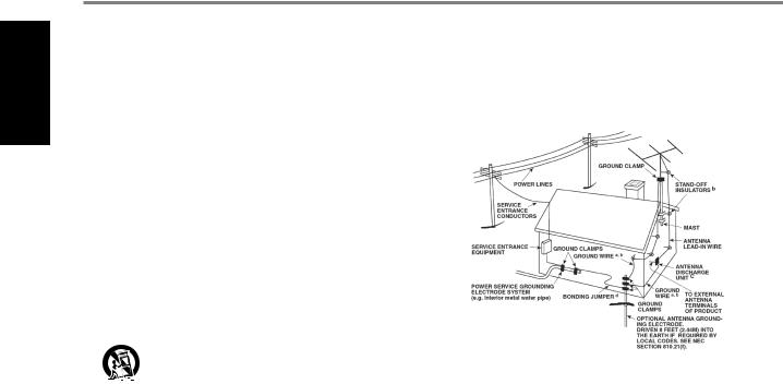
14.Outdoor Antenna Grounding - If an outside antenna or cable system is connected to the product, be sure the antenna or cable system is grounded so as to provide some protection against voltage surges and built-up static charges. Article 810 of the National Electrical Code, ANSI/NFPA 70, provides information with regard to proper grounding of the mast and supporting structure, grounding of the lead-in wire to an antenna discharge unit, size of grounding conductors, location of antenna discharge unit, connection to grounding electrodes, and requirements for the grounding electrode.
NOTE TO CATV SYSTEM INSTALLER
This reminder is provided to call the CATV system installer’s attention to Section 820-40 of the NEC which provides guidelines for proper grounding and, in particular, specifies that the cable ground shall be connected to the grounding system of the building, as close to the point of cable entry as practical.
15.Lightning - For added protection for this product during a lightning storm, or when it is left unattended and unused for long periods of time, unplug it from the wall outlet and disconnect the antenna or cable system. This will prevent damage to the product due to lightning and power-line surges.
16.Power Lines - An outside antenna system should not be located in the vicinity of overhead power lines or other electric light or power circuits, or where it can fall into such power lines or circuits. When installing an outside antenna system, extreme care should be taken to keep from touching such power lines or circuits as contact with them might be fatal.
17.Overloading - Do not overload wall outlets, extension cords, or integral convenience receptacles as this can result in a risk of fire or electric shock.
18.Flame Sources - No naked flame sources, such as lighted candles, should be placed on the product.
19.Object and Liquid Entry - Never push objects of any kind into this product through openings as they may touch dangerous voltage points or short-out parts that could result in a fire or electric shock. Never spill liquid of any kind on the product.
20.Headphones - Excessive sound pressure form earphones and headphones can cause hearing loss.
21.Damage Requiring Service - Unplug this product from the wall outlet and refer servicing to qualified service personnel under the following conditions:
a.When the power-supply cord or plug is damaged.
b.If liquid has been spilled, or objects have fallen into the product.
c.If the product has been exposed to rain or water.
d.If the product does not operate normally by following the operating instructions. Adjust only those controls that are covered by the operating instructions as an improper adjustment of other controls may result in damage and will often require extensive work by a qualified technician to restore the product to its normal operation.
e.If the product has been dropped or damaged in any way.
f.When the product exhibits a distinct change in performance-this indicates a need for service.
22.Replacement Parts - When replacement parts are required, be sure the service technician has used replacement parts specified by the manufacturer or have the same characteristics as the original part. Unauthorized substitutions may result in fire, electric shock, or other hazards.
2
IMPORTANT SAFETY INSTRUCTIONS
23.Battery Disposal - When disposing of used batteries, please comply with governmental regulations or environmental public instruction’s rules that apply in your country or area.
24.Safety Check - Upon completion of any service or repairs to this product, ask the service technician to perform safety checks to determine that the product is in proper operating condition.
25.Wall or Ceiling Mounting - The product should be mounted to a wall or ceiling only as recommended by the manufacturer.
WARNING
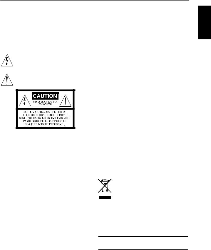
The lightning flash with arrowhead symbol, within an equilateral triangle, is intended to alert the user to the presence of uninsulated “dangerous voltage” within the product’s enclosure that may be of sufficient magnitude to constitute a risk of electric shock to persons
The exclamation point within an equilateral triangle is intended to alert the user to the presence of important operating and maintenance (servicing) instructions in the literature accompanying the appliance.
THE EQUIPMENT MUST BE CONNECTED TO AN EARTHED MAINS SOCKET-OUTLET.
CAUTION REGARDING PLACEMENT
To maintain proper ventilation, be sure to leave a space around the unit (from the largest outer dimensions including projections) than is equal to, or greater than shown below.
Left and Right Panels: 10 cm Rear Panel: 10 cm
Top Panel: 10 cm
FCC STATEMENT
This equipment has been tested and found to comply with the limits for Class B digital device, pursuant to Part 15 of the FCC Rules. These limits are designed to provide reasonable protection against harmful interference in a residential installation. This equipment generates, uses, and can radiate radio frequency
energy and, if not installed and used in accordance with the instructions, may cause harmful interference to radio communications. However, there is no guarantee that interference will not occur in a particular installation. If this equipment does cause harmful interference to radio or television reception, which can be determined
by turning the equipment off and on, the user is encouraged to try to correct the interference by one or more of the following measures:
•Reorient or relocate the receiving antenna.
•Increase the separation between the equipment and receiver.
•Connect the equipment into an outlet on a circuit different from that to which the receiver is connected.
•Consult the dealer or an experienced radio TV technician for help.
CAUTION
•Changes or modifications to this equipment not expressly approved by NAD Electronics for compliance could void the user’s authority to operate this equipment.
•This device complies with Part 15 of the FCC Rules / Industry Canada licenceexempt RSS standard(s). Operation is subject to the following two conditions: 1 This device may not cause harmful interference, and
2 This device must accept any interference received, including interference that may cause undesired operation.
•Under Industry Canada regulations, this radio transmitter may only operate using an antenna of a type and maximum (or lesser) gain approved for the transmitter by Industry Canada. To reduce potential radio interference to other users, the antenna type and its gain should be so chosen that the equivalent isotropically radiated power (e.i.r.p.) is not more than that necessary for successful communication.
•To prevent electric shock, match wide blade of plug to wide slot, fully insert.
•Marking and rating plate can be found at the rear panel of the apparatus.
•To reduce the risk of fire or electric shock, do not expose this apparatus to rain or moisture. The apparatus shall not be exposed to dripping or splashing and that no objects filled with liquids, such as vases, shall be placed on apparatus.
•Mains plug is used as disconnect device and it should remain readily operable during intended use. In order to disconnect the apparatus from the mains completely, the mains plug should be disconnected from the mains socket outlet completely.
•Battery shall not be exposed to excessive heat such as sunshine, fire or the like.
•Danger of explosion if battery is incorrectly replaced. Replace only with the same or equivalent type.
•An appliance with a protective earth terminal should be connected to a mains outlet with a protective earth connection.
MPE REMINDER
To satisfy FCC/IC RF exposure requirements, a separation distance of 20 cm or more should be maintained between the antenna of this device and persons during device operation. To ensure compliance, operations at closer than this distance is not recommended.
IF IN DOUBT CONSULT A COMPETENT ELECTRICIAN.
This product is manufactured to comply with the radio interference requirements of EEC DIRECTIVE 2004/108/EC.
NOTES ON ENVIRONMENTAL PROTECTION
At the end of its useful life, this product must not be disposed of with
regular household waste but must be returned to a collection point for the recycling of electrical and electronic equipment. The symbol on the product, user’s manual and packaging point this out.
The materials can be reused in accordance with their markings. Through re-use, recycling of raw materials, or other forms of recycling of old products, you are making an important contribution to the protection of our environment.
Your local administrative office can advise you of the responsible waste disposal point.
RECORD YOUR MODEL NUMBER (NOW, WHILE YOU CAN SEE IT)
The model and serial number of your new C 368 are located on the back of the cabinet. For your future convenience, we suggest that you record these numbers here:
Model number : . . . . . . . . . . . . . . . . . . . . . .
Serial number :. . . . . . . . . . . . . . . . . . . . . .
ENGLISH
NAD is a trademark of NAD Electronics International, a division of Lenbrook Industries Limited Copyright 2017, NAD Electronics International, a division of Lenbrook Industries Limited
3

ENGLISH
INTRODUCTION
GETTING STARTED
IMPORTANT SAFETY INSTRUCTIONS |
2 |
|
|
WHAT’S IN THE BOX |
|||
|
|
INTRODUCTION |
|
GETTING STARTED. . . . . . . . . . . . . . . . . . . . . . . . |
4 |
WHAT’S IN THE BOX. . . . . . . . . . . . . . . . . . . . . . . . . |
.4 |
CHOOSING A LOCATION . . . . . . . . . . . . . . . . . . . . . . |
. 4 |
RESTORING C 368 TO ITS FACTORY DEFAULT SETTINGS. . . . . . . |
4 |
IDENTIFICATION OF CONTROLS |
|
FRONT PANEL.. . . . . . . . . . . . . . . . . . . . . . . . . . 5 |
|
REAR PANEL . . . . . . . . . . . . . . . . . . . . . . . . . . . |
6 |
MDC CLASSIC UPGRADE SLOTS. . . . . . . . . . . . . . . . . . . |
.8 |
DD HDM-1 (DIRECT DIGITAL HDMI). . . . . . . . . . . . . . . . . |
.8 |
DD USB 2.0. . . . . . . . . . . . . . . . . . . . . . . . . . . . . . |
8 |
MDC BluOS. . . . . . . . . . . . . . . . . . . . . . . . . . . . . . |
8 |
SR 9 REMOTE CONTROL. . . . . . . . . . . . . . . . . . . . . . |
9 |
USING THE SR 9 REMOTE CONTROL. . . . . . . . . . . . . . . . . |
.9 |
USING THE SR 9 REMOTE CONTROL LIBRARY. . . . . . . . . . . . |
11 |
NAD REMOTE APP. . . . . . . . . . . . . . . . . . . . . . . |
12 |
USING THE NAD REMOTE APP. . . . . . . . . . . . . . . . . . . . |
12 |
OPERATION |
|
USING THE C 368. . . . . . . . . . . . . . . . . . . . . . . . . |
13 |
ACCESS MAIN MENU . . . . . . . . . . . . . . . . . . . . . . . |
13 |
NAVIGATING THE MENU OPTIONS AND MAKING CHANGES. . . . . |
13 |
SOURCE SETUP.. . . . . . . . . . . . . . . . . . . . . . . . . . |
13 |
ENABLED. . . . . . . . . . . . . . . . . . . . . . . . . . . . . . |
13 |
NAME. . . . . . . . . . . . . . . . . . . . . . . . . . . . . . . . |
13 |
SETTINGS. . . . . . . . . . . . . . . . . . . . . . . . . . . . . |
13 |
TONE CONTROLS.. . . . . . . . . . . . . . . . . . . . . . . . . |
13 |
BASS, TREBLE, BALANCE. . . . . . . . . . . . . . . . . . . . . . . |
14 |
FILTERS. . . . . . . . . . . . . . . . . . . . . . . . . . . . . . . |
14 |
PRE OUT/SUBWOOFER. . . . . . . . . . . . . . . . . . . . . . . |
14 |
SPEAKER CHANNEL. . . . . . . . . . . . . . . . . . . . . . . . |
14 |
TEMPORARY DISPLAY . . . . . . . . . . . . . . . . . . . . . . . . |
14 |
DIMMER.. . . . . . . . . . . . . . . . . . . . . . . . . . . . . . |
15 |
NETWORK STANDBY. . . . . . . . . . . . . . . . . . . . . . . . . . . . . . . . . . . . . . . . . . . . . . . . |
15 |
AUTO STANDBY. . . . . . . . . . . . . . . . . . . . . . . . . . . |
15 |
AUTO SENSE . . . . . . . . . . . . . . . . . . . . . . . . . . . . |
15 |
IR CHANNEL.. . . . . . . . . . . . . . . . . . . . . . . . . . . . |
16 |
IR LEARNING DEVICE . . . . . . . . . . . . . . . . . . . . . . . |
16 |
BT WORK MODE. . . . . . . . . . . . . . . . . . . . . . . . . . . |
17 |
C368 AS A BLUETOOTH SINK. . . . . . . . . . . . . . . . . . . . |
17 |
C368 AS A BLUETOOTH SOURCE . . . . . . . . . . . . . . . . . . |
18 |
VOLUME DISPLAY MODE. . . . . . . . . . . . . . . . . . . . . . |
18 |
FIRMWARE VERSION. . . . . . . . . . . . . . . . . . . . . . . . . |
19 |
FIRMWARE UPGRADE. . . . . . . . . . . . . . . . . . . . . . . |
19 |
MDC CARD UPGRADE. . . . . . . . . . . . . . . . . . . . . . . . |
19 |
BLUOS SETUP . . . . . . . . . . . . . . . . . . . . . . . . . . . . |
19 |
REFERENCE
SPECIFICATIONS. . . . . . . . . . . . . . . . . . . . . . . . .20
Packed with your C 368 you will find
•Two detachable mains power cord
•SR 9 remote control with 2 AA batteries
•Bluetooth antenna
•Quick Setup Guide
SAVE THE PACKAGING
Please save the box and all of the packaging in which your C 368 arrived. Should you move or need to transport your C 368, this is the safest container in which to do so. We’ve seen too many otherwise perfect components damaged in transit for lack of a proper shipping carton so, please: Save that box!
CHOOSING A LOCATION
Choose a location that is well ventilated (with at least several inches to both sides and behind), and that will provide a clear line of sight, within 25 feet / 8 meters, between the C 368’s front panel and your primary
listening/viewing position—this will ensure reliable infrared remote control communications. The C 368 generates a modest amount of heat, but nothing that should trouble adjacent components.
RESTORING C 368 TO ITS FACTORY DEFAULT SETTINGS
Press and hold both front panel’s a SOURCE s buttons until the display shows “FACTORY RESET”. Release both a SOURCE s buttons afterwards.
4
|
|
|
|
|
IDENTIFICATION OF CONTROLS |
|
||
|
|
|
|
|
|
|
FRONT PANEL |
|
|
NAD |
|
|
Hybrid Digital DAC Amplifier C 368 |
|
VOLUME |
ENGLISH |
|
|
|
|
|
|
||||
|
|
|
|
|
|
|
|
|
|
|
|
|
|
|
SOURCE |
|
|
|
|
|
|
|
|
|
© NAD C368 |
|
1 |
2 |
3 |
4 |
5 |
6 |
7 |
8 |
|
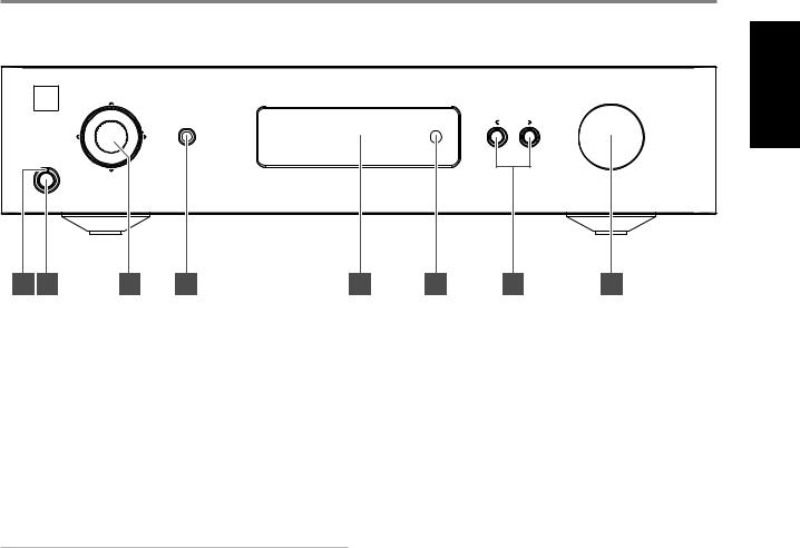
1 POWER INDICATOR |
5 |
•This indicator will be amber when the C 368 is in standby mode.
•When the C 368 is powered up from standby mode, this indicator will change from amber to blue color.
2STANDBY BUTTON
•Press Standby button to switch ON the C 368 from standby mode. The Power indicator will change from amber to blue color.
•Pressing Standby button again switches back C 368 to standby
mode. The Power indicator will change from blue to amber color. |
6 |
•The Standby button cannot activate the C 368 if the rear panel POWER switch is off.
IMPORTANT NOTES
For the Standby button to activate, the following must occur:
aThe supplied power cord from the C 368 must be plugged in to a power source.
bThe rear panel POWER switch must be set to ON.
3 NAVIGATION AND ENTER BUTTONS |
7 |
•The navigation [d/f/a/s] and [ENTER] buttons are used to go through menu options and selections.
• Use [d/f/a/s] to go up, down, left or right given options or |
8 |
selections. |
|
•The middle round button is designated as [ENTER] button. This is normally pressed to complete a selection, procedure, sequence or other applicable functions.
4HEADPHONE
•A 1/4” stereo jack socket is supplied for headphone listening and will work with conventional headphones of any impedance.
•The volume, tone and balance controls are operative for headphone listening. Use a suitable adapter to connect headphones with other types of sockets, such as 3.5mm “personal stereo” jack plugs.
DISPLAY
•Show visual and menu information according to the selected settings.
•The following Main menu options are shown in the display - Source Setup, Settings and BluOS Setup (available if MDC BluOS module is installed).
•Use the SR 9 remote control or front panel navigation [d/f/a/s] and [ENTER] buttons to go through menu options and selections.
REMOTE SENSOR
•Point the SR 9 remote control at the remote sensor and press the buttons.
•Do not expose the remote sensor of the C 368 to a strong light source such as direct sunlight or illumination. If you do so, you may not be able to operate the C 368 with the remote control.
Distance: About 23ft (7m) from the front of the remote sensor. Angle: About 30o in each direction of the front of the remote sensor.
aSOURCE s
•Press a SOURCE or SOURCE s to select Sources.
VOLUME
•The VOLUME control adjusts the overall loudness of the signal sent to the loudspeakers. The Volume control is characterized by perfect signal tracking and channel balance. It provides a highly linear and low noise operation.
•Turn clockwise to increase the volume level and counter clockwise to lower it.
•The default volume level is -20 dB.
•If the volume level is higher than -20 dB when the unit goes into standby mode, either via the front panel Standby button, the SR 9 remote’s Power Off button, or the unit’s auto standby settings, then when the unit wakes up the volume level will be reset to the default -20 dB. If, however, the volume level is lower than -20 dB when the unit goes into standby mode, that level setting will be preserved when the unit wakes up.
5

IDENTIFICATION OF CONTROLS
REAR PANEL
ENGLISH |
11 |
12 |
|
13 |
|
|
|
14 |
|
|
|
|
|
|
|
||
|
|
|
|
|
|
|
|
|
|
|
|
|
|
|
|
|
|
|
|
|
|
|
|
|
|
|
|
|
|
RIGHT |
SPEAKERS |
LEFT |
|
|
|
|
|
|
BT |
|
|
|
|
|
|
|
|
|
A |
|
|
POWER |
|
|
|
|
ANTENNA |
|
|
|
|
|
|
|
|
|
|
|
|
|
|
M o d u l a r |
|
|
SERVICE |
|
GND |
|
|
|
RS232 |
|
|
|
|
|
|
ON |
|
D e s i g n |
|
|
|
|
|
|
|
|
|
|
100-120V/220-240V~50/60Hz |
||||||
C o n s t r u c t i o n |
|
|
|
|
|
|
|
|
|
|
|
BRIDGE MODE |
|
||||
|
|
|
Serial No./N |
de serie |
|
|
|
|
|
|
|
|
|
|
|
||
|
|
|
|
|
|
|
|
|
RIGHT |
SPEAKERS |
LEFT |
|
|
|
|||
|
|
OPTICAL IN |
COAXIAL IN |
PHONO IN |
LINE 1 IN |
LINE 2 IN |
PRE-OUT/SUBW |
IR |
TRIGGER +12V |
|
|
B |
|
|
|
|
|
|
|
1 |
2 |
1 |
L |
L |
L |
L |
IN |
IN |
|
|
|
|
|
|
|
|
|
|
|
|
|
|
|
|
|
|
|
|
|
|
|
||
M o d u l a r |
|
|
|
|
MM |
|
|
|
OUT |
|
BRIDGE MODE |
|
|
|
|
|
|
D e s i g n |
|
|
|
|
|
|
|
|
|
|
|
|
|
|
|
|
|
C o n s t r u |
c t i o n |
|
|
|
|
|
|
|
|
|
OFF |
ON |
|
|
|
|
|
|
|
|
|
2 |
R |
R |
R |
R |
|
|
(STEREO) |
(MONO) |
BRIDGE MODE |
|
|
|
|
|
|
|
|
|
|
|
|
|
|
|
|
|
|
|
|
|
© NAD C368 |
|
|
|
1 |
|
|
2 |
|
3 |
4 |
5 |
6 |
|
|
7 |
8 |
9 |
10 |
ATTENTION!
Please ensure that the C 368 is powered off or unplugged from the main power source before making any connections. It is also advisable to power down or unplug all associated components while making or breaking any signal or AC power connections.
1COAX 1-2, OPT 1-2
•Connect to the corresponding optical or coaxial digital output of sources such as CD or BD/DVD players, digital cable box, digital tuners and other applicable components.
2PHONO IN, LINE 1-2 IN
PHONO: Input for a Moving Magnet (MM) phono cartridge. Connect the twin RCA lead from your turntable to this input if you are using a Moving Magnet cartridge.
LINE1, LINE 2: Input for line level sources such as CD player, tuner or any compatible devices. Use a twin RCA-to-RCA lead to connect the source device’s left and right “Audio Output” to this input.
3PRE-OUT/SUBW
•These output terminals have dual function. They are used either as PRE-OUT or SUBWOOFER terminals.
•The C 368 and associated external devices must be turned OFF always before connecting or disconnecting anything to the PREOUT/SUBW sockets.
PRE-OUT
•The PRE OUT/SUBW sockets make it possible to use the C 368 as a full range preamplifier to an external power amplifier.
•Use dual RCA cable to connect PRE-OUT/SUBW to the corresponding analog audio input of compatible devices such as amplifiers, receivers or other applicable devices.
•PRE-OUT/SUBW will be affected by the C 368’s volume control settings. Turn the VOLUME control to adjust the output level of the PRE OUT/SUBW sockets.
SUBWOOFER
•Use a dual RCA cable to connect PRE OUT/SUBW to the low level input of a powered subwoofer.
•Low frequency information up to 150 Hz is sent to the connected subwoofer via PRE-OUT/SUBW. This is based from 2nd order Linkwitz-Riley Crossover Filter @150 Hz.
4IR IN/IR OUT
•These mini-jacks accept and output remote-controlled codes in electrical format, using industry-standard protocols, for use with “IR-repeater” and multi-room systems and related technologies.
•All NAD products with IR IN/IR OUT features are fully compatible with the C 368. For non-NAD models, please check with your other product’s service specialists with respect to their compatibility to the C 368’s IR features.
IR IN
•This input is connected to the output of an IR (infrared) repeater (Xantech or similar) or the IR output of another compatible device to allow control of the C 368 from a remote location.
IR OUT
•Connect IR OUT to the IR IN jack of a compatible device.
•Command and control the linked compatible device by directing its own remote control to C 368’s infrared receiver.
5TRIGGER +12V +12V TRIGGER OUT
•The +12V TRIGGER OUT is used for controlling external equipment equipped with a +12V trigger input.
•Connect this +12V TRIGGER OUT to the other equipment’s corresponding +12V DC input jack using a mono cable with 3.5mm male plug.
•This output will be 12V when the C 368 is ON and 0V when it is either OFF or in standby mode.
+12V TRIGGER IN
•With this input triggered by a 12V DC supply, the C 368 can be switched ON remotely from standby mode by compatible devices such as amplifiers, preamplifiers, receivers, etc. If the 12V DC supply is cut off, the C 368 will return to standby mode.
•Connect this +12V Trigger input to the remote device’s corresponding +12V DC output jack using a mono cable with 3.5mm male plug. The controlling device must be equipped with a +12V trigger output to use this feature.
6
IDENTIFICATION OF CONTROLS
REAR PANEL
NOTE
If there is a stereo jack connected to +12V TRIGGER IN, the C 368 cannot be powered ON/OFF using the front panel Standby button or SR 9’s ON/OFF buttons. The stereo jack has to be unplugged to resume normal powering up of the unit via front panel Standby button or SR 9’s ON/OFF buttons.
6BRIDGE MODE
The C 368 amplifier can be configured to be MONO (Bridge Mode), more than doubling its output power. This way, the C 368 can be used as part of a high power stereo or home-theatre system, by connecting additional power amplifiers.
•In BRIDGED MODE (switch at ON (MONO) setting), the C 368 will produce approximately 300W into an 8 ohm loudspeaker. In this mode, the amplifier sections will react as though the speaker impedance has been halved. Low impedance speakers (under 8 ohms) are not recommended when using Bridge Mode as these may cause the amplifier’s thermal cut-out to operate if played at high levels.
•Set the BRIDGE MODE switch to the “ON (MONO)” position and connect the speaker to the terminals marked “L +” and “R-” ensuring that the “L+” is connected to the “+” terminal of your speaker and the “R-” is connected to the speaker’s “ - ” terminal.
•Connect the source to the Left input sockets only. Do not connect anything to the Right Input socket when Bridge Mode is selected.
7SPEAKERS
•The C 368 has two sets of SPEAKER connections which are identical in function (parallel connection).
•Connect C 368’s Right speaker terminals marked “R +” and “R-” to the corresponding “+” and “-“ terminals of your designated right speaker. Repeat the same for C 368’s Left speaker terminals and corresponding left speaker.
•Double check the speaker connections before powering up the C 368.
IMPORTANT NOTES
•The blue terminals must never be connected to ground (earth).
•Never connect the blue terminals together or to any common ground device.
•Do not connect the output of this amplifier to any headphone adapter, speaker switch or any device that uses common ground for left and right channels.
NOTES
•Use 16 gauge (American Wire Gauge or AWG) or lower stranded wire. Connections to the C 368 can be made with banana-type plugs.
•Bare wire or pins can also be used by loosening the terminal’s plastic nut, making a clean, neat connection and re-tightening. To minimize the danger of a short circuit, ensure that only 1/2-inch of exposed wire or pin is used to connect and no loose strands of speaker wire.
8POWER
•Supplies the AC mains power to the C 368.
•When the POWER switch is set to ON position, the C 368 goes to standby mode as shown by the amber status condition of the front panel Power indicator.
•Press the front panel Standby button or SR 9’s remote control’s [ON] button to switch ON the C 368 from standby mode.
•If you do not intend to use the C 368 for long periods of time (such as when on vacation), switch off the POWER switch.
•With POWER switched off, neither the front panel Standby button nor SR 9 remote control’s [ON] button can activate the C 368.
9FUSE HOLDER
•Only qualified NAD service technicians can have access to this fuse holder. Opening this fuse holder may cause damage thus voiding the warranty of your C 368.
10AC MAINS INPUT
•The C 368 comes supplied with two separate mains power cords. Select the mains power cord appropriate for your region.
•Before connecting the plug to the mains power source, ensure that it is firmly connected to the C 368’s AC Mains input socket.
•Always disconnect the mains power plug from the mains power source before disconnecting the cable from the C 368’s AC Mains input socket.
11SERVICE
•Use for servicing purposes only. Not for consumer use.
12BLUETOOTH ANTENNA TERMINAL
•Install supplied Bluetooth antenna to this Bluetooth antenna terminal.
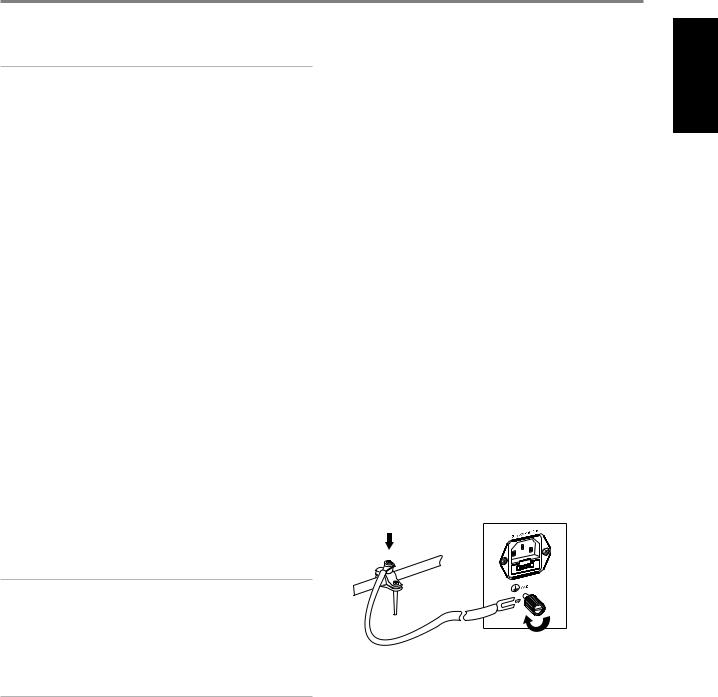
13GROUND TERMINAL
•Ensure that the C 368 is plugged-in to a grounded AC wall outlet.
•If necessary, use this ground terminal to connect to ground a phono or turntable source for PHONO input.
•If a separate earth ground is necessary, use this terminal to ground your C 368. The C 368 can be connected to ground by connecting a ground lead wire or similar to this terminal. After insertion, tighten the terminal to secure the lead.
EXAMPLE ILLUSTRATION OF GROUNDING THE C 368 VIA THE REAR PANEL GROUND TERMINAL
14RS 232
NAD is a certified partner of AMX and Crestron and fully supports these external devices. Check out the NAD website for information about AMX and Crestron compatibility with NAD. See your NAD audio specialist for more information.
•Connect this interface using RS-232 serial cable (not supplied) to any Windows compatible PC to allow remote control of the C 368 via compatible external controllers.
•Refer to the NAD website for information about RS232 Protocol documents and PC interface program.
ENGLISH
7
Loading...