


 Loading...

 ® T 758
AV Surround Sound Receiver
ENGLISH
Owner’s Manual
ENGLISH
IMPORTANT SAFETY INSTRUCTIONS
SAVE THESE INSTRUCTIONS FOR LATER USE.
FOLLOW ALL WARNINGS AND INSTRUCTIONS MARKED ON THE AUDIO EQUIPMENT.
1Read instructions - All the safety and operating instructions should be read before the product is operated.
2Retain instructions - The safety and operating instructions should be retained for future reference.
3Heed Warnings - All warnings on the product and in the operating instructions should be adhered to.
4Follow Instructions - All operating and use instructions should be followed.
5Cleaning - Unplug this product from the wall outlet before cleaning. Do not use liquid cleaners or aerosol cleaners. Clean only with a dry cloth.
6Attachments - Do not use attachments not recommended by the product manufacturer as they may cause hazards.
7Water and Moisture - Do not use this product near water-for example, near a bath tub, wash bowl, kitchen sink, or laundry tub; in a wet basement; or near a swimming pool; and the like.
8Accessories - Do not place this product on an unstable cart, stand, tripod, bracket, or table. The product may fall, causing serious injury to a child or adult, and serious damage to the product. Use only with a cart, stand, tripod, bracket, or table recommended by the manufacturer, or sold with the product. Any mounting of the product should follow the manufacturer’s instructions, and should use a mounting accessory recommended by the manufacturer.
9A product and cart combination should be moved with care. Quick
stops, excessive force, and uneven surfaces may cause the product and cart combination to overturn.
10Ventilation - Slots and openings in the cabinet are provided for ventilation and to ensure reliable operation of the product and to protect it from overheating, and these openings must not be blocked or covered. The openings should never be blocked by placing the product on a bed, sofa, rug, or other similar surface. This product should not be placed in a built-in installation such as a bookcase or rack unless proper ventilation is provided or the manufacturer’s instructions have been adhered to.
11Power Sources - This product should be operated only from the type of power source indicated on the marking label. If you are not sure of the type of power supply to your home, consult your product dealer or local power company. The primary method of isolating the amplifier from the mains supply is to disconnect the mains plug. Ensure that the mains plug remains accessible at all times. Unplug the AC power cord from the AC outlet if the unit will not be used for several months or more.
12Grounding or Polarization - This product may be equipped with a polarized alternating current line plug (a plug having one blade wider than the other). This plug will fit into the power outlet only one way. This is a safety feature. If you are unable to insert the plug fully into the outlet, try reversing the plug. If the plug should still fail to fit, contact your electrician to replace your obsolete outlet. Do not defeat the safety purpose of the polarized plug.
13Power Cord Protection - Power supply cords should be routed so that they are not likely to be walked on or pinched by items placed upon or against them, paying particular attention to cords at plugs, convenience receptacles, and the point where they exit from the product.
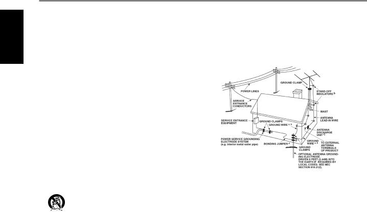
14Outdoor Antenna Grounding - If an outside antenna or cable system is connected to the product, be sure the antenna or cable system is grounded so as to provide some protection against voltage surges and built-up static charges. Article 810 of the National Electrical Code, ANSI/NFPA 70, provides information
with regard to proper grounding of the mast and supporting structure, grounding of the lead-in wire to an antenna discharge unit, size of grounding conductors, location of antenna discharge unit, connection to grounding electrodes, and requirements for the grounding electrode.
NOTE TO CATV SYSTEM INSTALLER
This reminder is provided to call the CATV system installer’s attention to Section 820-40 of the NEC which provides guidelines for proper grounding and, in particular, specifies that the cable ground shall be connected to the grounding system of the building, as close to the point of cable entry as practical.
15Lightning - For added protection for this product during a lightning storm, or when it is left unattended and unused for long periods of time, unplug it from the wall outlet and disconnect the antenna or cable system. This will prevent damage to the product due to lightning and power line surges.
16Power Lines - An outside antenna system should not be located in the vicinity of overhead power lines or other electric light or power circuits, or where it can fall into such power lines or circuits. When installing an outside antenna system, extreme care should be taken to keep from touching such power lines or circuits as contact with them might be fatal.
17Overloading - Do not overload wall outlets, extension cords, or integral convenience receptacles as this can result in a risk of fire or electric shock.
18Object and Liquid Entry - Never push objects of any kind into this product through openings as they may touch dangerous voltage points or short-out parts that could result in a fire or electric shock. Never spill liquid of any kind on the product.
WARNING: THE APPARATUS SHOULD NOT BE EXPOSED TO DRIPPING OR SPLASHING, AND OBJECTS FILLED WITH LIQUIDS, SUCH AS VASES,
SHOULD NOT BE PLACED ON THE APPARATUS. AS WITH ANY ELECTRONIC PRODUCTS, USE CARE NOT TO SPILL LIQUIDS INTO ANY PART OF THE SYSTEM. LIQUIDS CAN CAUSE A FAILURE AND/OR A FIRE HAZARD.
19Damage Requiring Service - Unplug this product from the wall outlet and refer servicing to qualified service personnel under the following conditions:
a)When the power supply cord or plug is damaged.
b)If liquid has been spilled, or objects have fallen into the product.
c)If the product has been exposed to rain or water.
d)If the product does not operate normally by following the operating instructions. Adjust only those controls that are covered by the operating instructions as an improper adjustment of other controls may result in damage and will often require extensive work by a qualified technician to restore the product to its normal operation.
e)If the product has been dropped or damaged in any way.
f)when the product exhibits a distinct change in performance-this indicates a need for service.
20Replacement Parts - When replacement parts are required, be sure the service technician has used replacement parts specified by the manufacturer or have the same characteristics as the original part. Unauthorized substitutions may result in fire, electric shock, or other hazards.
21Safety Check - Upon completion of any service or repairs to this product, ask the service technician to perform safety checks to determine that the product is in proper operating condition.
2

IMPORTANT SAFETY INSTRUCTIONS
22Wall or Ceiling Mounting - The product should be mounted to a wall or ceiling only as recommended by the manufacturer.
23Heat - The product should be situated away from heat sources such as radiators, heat registers, stoves or other products (including amplifiers) that produce heat.
24Headphones - Excessive sound pressure form earphones and headphones can cause hearing loss.
25Battery Disposal - When disposing of used batteries, please comply with governmental regulations or environmental public instruction’s rules that apply in your country or area. Batteries (battery pack or batteries installed) must not be exposed to excessive heat such as sunshine, fire or the like.
CAUTION
Danger of explosion if battery is incorrectly replaced.
Replace only with the same or equivalent type.
WARNING
TO REDUCE THE RISK OF FIRE OR ELECTRIC SHOCK, DO NOT EXPOSE THIS PRODUCT TO RAIN OR MOISTURE.
CAUTION
TO PREVENT ELECTRIC SHOCK, MATCH WIDE BLADE OF PLUG TO WIDE SLOT, FULLY INSERT.
THE LIGHTNING FLASH WITH ARROWHEAD SYMBOL, WITHIN AN EQUILATERAL TRIANGLE, IS INTENDED TO ALERT THE USER TO THE PRESENCE OF UNINSULATED “DANGEROUS VOLTAGE”WITHIN THE PRODUCT’S ENCLOSURE THAT MAYBE OF SUFFICIENT MAGNITUDE TO CONSTITUTE A RISK OF ELECTRIC SHOCK TO PERSONS.
THE EXCLAMATION POINT WITHIN AN EQUILATERAL TRIANGLE IS INTENDED TO ALERT THE USER TO THE PRESENCE OF IMPORTANT OPERATING
AND MAINTENANCE (SERVICING) INSTRUCTIONS IN THE LITERATURE ACCOMPANYING THE APPLIANCE.
THE EQUIPMENT MUST BE CONNECTED TO AN EARTHED MAINS SOCKET-OUTLET.
The disconnect device of the apparatus is its mains plug. Cut off power to the apparatus by disconnecting its mains plug from the mains outlet.
The mains plug of the apparatus should be easily accessible or free from any obstruction during intended use.
CAUTION
Changes or modifications to this equipment not expressly approved by NAD Electronics for compliance could void the user’s authority to operate this equipment.
CAUTION REGARDING PLACEMENT
To maintain proper ventilation, be sure to leave a space around the unit (from the largest outer dimensions including projections) that is equal to or greater than shown below.
Left and Right Panels: 10 cm Rear Panel: 10 cm
Top Panel: 20 cm
NOTES ON ENVIRONMENTAL PROTECTION
At the end of its useful life, this product must not be disposed of with regular household waste but must be returned to a collection point for the recycling of electrical and electronic equipment. The symbol on the product, user’s manual and packaging, point this out.
The materials can be reused in accordance with their markings. Through re-use, recycling of raw materials or other forms of recycling of old products, you are making an important contribution to the protection of our environment. Your local administrative office can advise you of the responsible waste disposal point.
INFORMATION ABOUT COLLECTION AND DISPOSAL OF WASTE BATTERIES (DIRECTIVE 2006/66/EC OF THE EUROPEAN PARLIAMENT AND THE COUNCIL OF EUROPEAN UNION) (FOR EUROPEAN CUSTOMERS ONLY)
Batteries bearing any of these symbols indicate that they should be treated as “separate collection” and not
as municipal waste. It is encouraged that necessary measures are implemented to maximize the separate
collection of waste batteries and to minimize the disposal of batteries as mixed municipal waste.
End-users are exhorted not to dispose waste batteries as unsorted municipal waste. In order to achieve a high level of recycling waste batteries, discard waste batteries separately and properly through an accessible collection
point in your vicinity. For more information about collection and recycling of waste batteries, please contact your local municipality, your waste disposal service or the point of sale where you purchased the items.
By ensuring compliance and conformance to proper disposal of waste batteries, potential hazardous effects on human health is prevented and the negative impact of batteries and waste batteries on the environment is minimized, thus contributing to the protection, preservation and quality improvement of the environment.
NOTE: THE T 758 IS NOT AN AUTO VOLTAGE UNIT. CONNECT ONLY TO THE PRESCRIBED AC OUTLET, I.E., 120V 60HZ OR 230V 50HZ.
WARNING: DO NOT INGEST BATTERY, CHEMICAL BURN HAZARD
The remote control supplied with this product contains a coin/button cell battery. If the coin/button cell battery is swallowed, it can cause severe internal burns in just 2 hours and can lead to death.
Keep new and used batteries away from the children. If the battery compartment does not close securely, stop using the product and keep it away from children.
If you think batteries might have been swallowed or placed inside a part of the body, seek immediate medical attention.
RECORD YOUR MODEL NUMBER (NOW, WHILE YOU CAN SEE IT)
The model and serial number of your new T 758 are located on the back of the cabinet. For your future convenience, we suggest that you record these numbers here:
Model no:. . . . . . . . . . . . . . . . . . . .
Serial no.: . . . . . . . . . . . . . . . . . . . . . . . . . . . . . . . . . . . . . .
NAD is a trademark of NAD Electronics International, a division of Lenbrook Industries Limited Copyright 2015, NAD Electronics International, a division of Lenbrook Industries Limited
ENGLISH
3

ENGLISH
INTRODUCTION
TABLE OF CONTENTS
IMPORTANT SAFETY INSTRUCTIONS . . . . . . . . . . . . . . . . . . . . . . . . . .2
INTRODUCTION
GETTING STARTED.. . . . . . . . . . . . . . . . . . . . . . . . . . . . . . . . . . . . . . . . . . . . . . . 5
WHAT’S IN THE BOX. . . . . . . . . . . . . . . . . . . . . . . . . .5 INITIAL SETUP. . . . . . . . . . . . . . . . . . . . . . . . . . . . .5 CHOOSING A LOCATION . . . . . . . . . . . . . . . . . . . . . . . 5 DEFAULT SOURCE SETTINGS .. . . . . . . . . . . . . . . . . . . . 5
IDENTIFICATION OF CONTROLS |
|
FRONT PANEL. . . . . . . . . . . . . . . . . . . . . . . . . . . . . . . . . . . . . . . . . . . . . . . . . . . . |
6 |
REAR PANEL .. . . . . . . . . . . . . . . . . . . . . . . . . . . . . . . . . . . . . . . . . . . . . . . . . . . . |
. 8 |
AVR 4 REMOTE CONTROL. . . . . . . . . . . . . . . . . . . . . . . . . . . . . . . . . . . . . . . . |
11 |
USING THE AVR 4 REMOTE CONTROL. . . . . . . . . . . . . . . |
11 |
LIBRARY. . . . . . . . . . . . . . . . . . . . . . . . . . . . . . . |
14 |
USING THE ZR 7 REMOTE CONTROL. . . . . . . . . . . . . . . . . |
14 |
ALTERNATE IR CHANNEL . . . . . . . . . . . . . . . . . . . . . . |
15 |
OPERATION |
|
USING THE T 758 - MAIN MENU. . . . . . . . . . . . . . . . . . . . . . . . . . . . . . . . . . . |
16 |
ABOUT THE ON-SCREEN DISPLAY (OSD). . . . . . . . . . . . . . |
16 |
MAIN MENU.. . . . . . . . . . . . . . . . . . . . . . . . . . . . |
16 |
LISTENING MODE . . . . . . . . . . . . . . . . . . . . . . . . . . |
16 |
ADJUSTING LISTENING MODES . . . . . . . . . . . . . . . . . . . |
17 |
DSP OPTIONS . . . . . . . . . . . . . . . . . . . . . . . . . . . . |
18 |
TONE CONTROLS.. . . . . . . . . . . . . . . . . . . . . . . . . |
18 |
ZONE CONTROLS. . . . . . . . . . . . . . . . . . . . . . . . . . . . . . . . . . . . . . . . . . . . . . . . . . . |
18 |
USING THE T 758 – SETUP MENU. . . . . . . . . . . . . . . . . . . . . . . . . . . . . . . . . |
19 |
SETUP MENU. . . . . . . . . . . . . . . . . . . . . . . . . . . . |
19 |
CONTROL SETUP. . . . . . . . . . . . . . . . . . . . . . . . . . |
19 |
SOURCE SETUP . . . . . . . . . . . . . . . . . . . . . . . . . . . |
20 |
SOURCE SETUP (NORMAL VIEW) . . . . . . . . . . . . . . . . . . |
20 |
SOURCE SETUP (TABLE VIEW). . . . . . . . . . . . . . . . . . . |
21 |
iPod SETUP. . . . . . . . . . . . . . . . . . . . . . . . . . . . . |
22 |
SPEAKER SETUP. . . . . . . . . . . . . . . . . . . . . . . . . . . |
22 |
AUDYSSEY SETUP . . . . . . . . . . . . . . . . . . . . . . . . . . |
22 |
SPEAKER CONFIGURATION. . . . . . . . . . . . . . . . . . . . . |
24 |
SPEAKER LEVELS. . . . . . . . . . . . . . . . . . . . . . . . . . |
24 |
SPEAKER DISTANCE . . . . . . . . . . . . . . . . . . . . . . . . . |
25 |
THANK YOU FOR CHOOSING NAD.
The T 758 AV Surround Sound Receiver is a technologically advanced and highly capable product yet we have invested great effort in making it simple and easy to use. The T 758 delivers a range of genuinely useful options for surround sound and stereo listening alike, using powerful digital signal processing and superbly accurate digital-audio circuitry. However, we have also been careful to ensure that the T 758 is as musically transparent, faithful
ADJUSTING THE VOLUME . . . . . . . . . . . . . . . . . . . . . . |
25 |
ZONE SETUP . . . . . . . . . . . . . . . . . . . . . . . . . . . . |
25 |
AMPLIFIER SETUP . . . . . . . . . . . . . . . . . . . . . . . . . . |
26 |
TRIGGER SETUP . . . . . . . . . . . . . . . . . . . . . . . . . . . |
26 |
LISTENING MODE SETUP. . . . . . . . . . . . . . . . . . . . . . |
26 |
DOLBY SETUP. . . . . . . . . . . . . . . . . . . . . . . . . . . . |
28 |
DTS SETUP . . . . . . . . . . . . . . . . . . . . . . . . . . . . . |
28 |
DTS SURROUND MODES. . . . . . . . . . . . . . . . . . . . . . |
28 |
ENHANCED STEREO. . . . . . . . . . . . . . . . . . . . . . . . . |
29 |
DISPLAY SETUP.. . . . . . . . . . . . . . . . . . . . . . . . . . |
29 |
A/V PRESETS. . . . . . . . . . . . . . . . . . . . . . . . . . . . |
30 |
LISTENING TO AM/FM RADIO.. . . . . . . . . . . . . . . . . . . . . . . . . . . . . . . . . . . . |
33 |
SELECTING A TUNER BAND. . . . . . . . . . . . . . . . . . . . |
33 |
STORING PRESETS (AM/FM/DAB).. . . . . . . . . . . . . . . . . |
33 |
CHOOSING THE TUNER MODE. . . . . . . . . . . . . . . . . . . |
33 |
ABOUT USER NAMES. . . . . . . . . . . . . . . . . . . . . . . . |
34 |
ABOUT RDS . . . . . . . . . . . . . . . . . . . . . . . . . . . . . |
34 |
LISTENING TO DAB RADIO. . . . . . . . . . . . . . . . . . . . . . . . . . . . . . . . . . . . . . . |
35 |
CONNECTING THE DAB MODULE . . . . . . . . . . . . . . . . . . |
35 |
DAB OPERATION . . . . . . . . . . . . . . . . . . . . . . . . . . |
35 |
SERVICE LIST . . . . . . . . . . . . . . . . . . . . . . . . . . . . |
36 |
DAB TUNER MODE . . . . . . . . . . . . . . . . . . . . . . . . . |
36 |
STATION ORDER. . . . . . . . . . . . . . . . . . . . . . . . . . . |
36 |
DRC. . . . . . . . . . . . . . . . . . . . . . . . . . . . . . . . . |
36 |
MANUAL SCAN.. . . . . . . . . . . . . . . . . . . . . . . . . . |
36 |
PRUNE LIST.. . . . . . . . . . . . . . . . . . . . . . . . . . . . |
36 |
RESET . . . . . . . . . . . . . . . . . . . . . . . . . . . . . . . . |
37 |
INFORMATION SETTINGS.. . . . . . . . . . . . . . . . . . . . . |
37 |
LISTENING TO YOUR iPod PLAYER. . . . . . . . . . . . . . . . . . . . . . . . . . . . . . . . |
38 |
CONNECTING THE OPTIONAL NAD IPD AND iPod PLAYER |
|
TO THE T 758. . . . . . . . . . . . . . . . . . . . . . . . . . . . |
38 |
CONTROL FEATURES AND SETTINGS. . . . . . . . . . . . . . . . |
38 |
NAD IPD 2. . . . . . . . . . . . . . . . . . . . . . . . . . . . . . |
39 |
TO VIEW VIDEOS OR PHOTOS LOADED IN YOUR iPod.. . . . . . . |
39 |
REFERENCE
TROUBLESHOOTING . . . . . . . . . . . . . . . . . . . . . . . . . . . . . . . . . . . . . . . . . . . . .40 SPECIFICATIONS.. . . . . . . . . . . . . . . . . . . . . . . . . . . . . . . . . . . . . . . . . . . . . . . .41
We encourage you to take a few minutes now to read right through this manual. Investing a little time here at the outset might save you a good deal of time later, and is by far the best way to ensure that you make the most of your investment in the T 758, and get the most from this powerful and flexible home-theater component.
to every video detail and spatially accurate as possible, incorporating much |
For warranty information contact your local distributor. |
of what we’ve learned from over three decades of experience designing |
|
audio, video and home-theater components. As with all our products, NAD’s |
|
“Music First” design philosophy guided the T 758’s design, such that it can |
|
confidently promise you both state-of-the-art surround home-theater and |
|
audiophile-quality music listening for years to come. |
|
NAD SHALL NOT BE HELD LIABLE FOR ANY TECHNICAL OR USER INTERFACE DISCREPANCIES IN THIS MANUAL.
THE T 758 OWNER’S MANUAL MAY BE SUBJECT TO CHANGE WITHOUT PRIOR NOTICE. CHECK OUT THE NAD WEBSITE FOR THE LATEST VERSION OF THE T 758 OWNER’S MANUAL.
4

WHAT’S IN THE BOX
Packed with your T 758 you will find
•AM loop antenna
•FM lead-type antenna
•Detachable mains power cord
•Audyssey microphone
•AVR 4 remote control with 2 AA batteries
•ZR 7 zone remote control with 3V CR2025 battery
•T 758 Quick Start Guide
SAVE THE PACKAGING
Please save the box and all of the packaging in which your T 758 arrived. Should you move or otherwise need to transport your T 758, this is by far the safest container in which to do so. We’ve seen too many otherwise perfect components damaged in transit for lack of a proper shipping carton, so please: Save that box!
INITIAL SETUP
Before you make the first connection to your T 758, you should have the arrangement of your listening room/home theater components and furniture mapped out, at least initially. Unfortunately, a discussion of the vital questions of loudspeaker placement and listening/viewing positions is beyond our scope here.
CHOOSING A LOCATION
Choose a location that is well ventilated (with at least several inches to both sides and behind), and that will provide a clear line of sight, within 25 feet/8 meters, between the T 758’s front panel and your primary listening/viewing position - this will ensure reliable infrared remote control communications. The T 758 generates a modest amount of heat, but nothing that should trouble adjacent components. It is especially important that sufficient ventilation be provided.
DEFAULT SOURCE SETTINGS
The following table lists the default SOURCE settings. Note that the Audio input settings show both digital and analog audio input. Digital input will always take precedence over analog audio input even if both are present.
Source |
Audio Input |
Video Input |
Source 1 |
HDMI 1/ Audio 1 |
HDMI 1 |
Source 2 |
HDMI 2/ Audio 2 |
HDMI 2 |
Source 3 |
Coaxial 1 |
Component Video Input 1 |
Source 4 |
Optical 1 |
Video 1 |
iPod |
Audio 3 |
S-Video |
Source 7 |
7.1 Channel Input |
Component Video Input 2 |
Front Input |
Optical Front Input/ Audio Front Input |
Video Front Input |
Media Player |
Audio Front MP |
|
Tuner |
|
|
For Video output, select the highest quality video format available on your TV/Monitor and utilize this for your Monitor OUT connection from the T 758 to the TV/Monitor. In most cases, this would be HDMI but for other TV/Monitor without HDMI input, the best quality connection could be Component Video, S-Video or Composite video input.
To modify the above default settings and for a better understanding of source setting and combinations, please refer to the item about “SOURCE SETUP” in the “USING THE T 758 - SETUP MENU” segment of the “OPERATION” section.
INTRODUCTION
GETTING STARTED
ENGLISH
5
ENGLISH
IDENTIFICATION OF CONTROLS
FRONT PANEL
1 |
|
2 |
|
3 |
|
4 |
|
5 |
|
6 |
|
7 |
|
8 |
|
9 |
|
|
|
|
|
|
|
|
|
|
|
|
|
|
|
|
|
AV Surround Sound Receiver T 758
a 

 s
s
A B C D
© NAD T 758
10
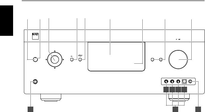
1STANDBY BUTTON
•Press this button to switch ON the T 758 from standby mode. The Standby LED indicator will turn from amber to blue and illuminate the VFD. Pressing the STANDBY button again turns the unit back to standby mode.
•The T 758 can also be switched ON from standby mode by pressing any of the front panel buttons.
2STANDBY LED
•This indicator will light up amber when the T 758 is at standby mode.
•When the T 758 is powered up from standby mode, this indicator
will illuminate blue. |
4 |
•If Zone 2 is still ON and STANDBY button is pressed to switch the T 758 to standby mode, the VFD will be extinguished but the
STANDBY LED remains illuminated blue. This indicates that Zone 2 |
5 |
is still active. In order to completely shut down the T 758 together with Zone 2, press and hold STANDBY button until the STANDBY LED turns amber.
3NAVIGATION and ENTER BUTTONS
The navigation [ a/s/d/f ] and [ENTER] buttons have various applications specific to given modes. The middle round button designated as [ENTER] button; this is normally pressed to complete a selection, procedure, sequence or other applicable functions.
AM/FM mode
Toggle [ENTER] button to switch between “Tune” and “Preset” mode. Select “Tune” mode.
•Pressing momentarily the [ a/s ] button will manually scan the AM or FM band.
•Press and hold [ a/s ]for more than 2 seconds to search up or down; the T 758’s tuner will stop at the next sufficiently strong signal it encounters.
•Note that this function “wraps” - that is, it will continue to search from one end of the AM or FM band to the other until it stops at a strong signal.
11 12
Toggle [ENTER] button to switch between “Tune” and “Preset” mode. Select “Preset” mode.
•Use [ d/f ] to step up or down AM/FM Presets. Unused presets are skipped over. Note that Presets must have been previously stored.
Refer also to the item about STORING PRESETS (AM/FM/DAB) at the LISTENING TO AM/FM RADIO section of the OPERATION page.
DAB mode (230V version model only)
•Use front panel [ a/s ] and [ENTER] buttons in combination with [MENU] button to select through applicable DAB menu options.
MENU
•Press to activate or deactivate OSD menu.
LISTENING MODE
•Toggle to select through the various Listening mode options.
•Depending on the format of the currently selected input (digital or analog, stereo or multichannel), various listening modes are available.
•Refer also to the item about LISTENING MODE under the USING THE T 758 - MAIN MENU segment of the OPERATION section.
6

IDENTIFICATION OF CONTROLS
FRONT PANEL
6VACUUM FLUORESCENT DISPLAY (VFD)
•Displays visual information about the current settings like the active Source, volume level, listening mode, audio format, applicable RDS/ DAB as well as iPod-related display information and other related indicators.
•Refer also to the item about DISPLAY SETUP under the USING THE T 758 - SETUP MENU segment of the OPERATION section.
7REMOTE SENSOR
•Point the AVR 4 remote control at the remote sensor and press the buttons.
•Do not expose the remote sensor of the T 758 to a strong light source such as direct sunlight or illumination. If you do so, you may not be able to operate the T 758 with the remote control.
Distance: About 23ft (7m) from the front of the remote sensor. Angle: About 30° in each direction of the front of the remote sensor.
8aSOURCE s
•Toggle through the input selections - Source 1, Source 2, Source 3, Source 4, iPod, Source 7, Front Input, Media Player and Tuner (AM/ FM/DAB as applicable). More Sources can be directly recalled upon enabling them at the Setup Menu.
•Refer also to the item about SOURCE SETUP under the USING THE T 758 - SETUP MENU segment of the OPERATION section.
9VOLUME
•The VOLUME control adjusts the overall loudness of the signal being fed to the loudspeakers or headphones.
•Turn clockwise to increase the volume level; counter clockwise to lower it.
10PHONES
•Accepts stereo headphone using a standard 1/4-inch stereo phone plug (use a suitable adaptor for headphones equipped with a smaller plug).
•Plugging in headphones automatically mutes output from the speakers.
•For headphone listening, the Front speakers must be set to “Large” at the “Speaker Configuration” of the Speaker Setup item at the Setup Menu; otherwise headphone bass response will be restricted.
•Plugging in headphones will automatically switch the T 758 to Stereo, Stereo Downmix or Analog Bypass modes.
11FRONT INPUT PORTS
•Use these convenience jacks for occasional sources such as a camcorder, video game console, any analog audio or optical digital audio sources and composite video sources.
•If your source has two output jacks indicative of stereo output, insert both jacks into the T 758’s corresponding Front “L” (item A) and “R (MONO)” input to achieve stereo output as well.
•On the other hand, if your source has a single audio out jack only or is marked “Mono output”, plug this into the T 758’s Front “R (MONO)” input (item B).
•Connect composite video output source to the front composite video input (item C).
•Use the front optical audio input (item D) for optical digital audio sources.
12FRONT MP/MIC INPUT
•Connect your Media Player’s standard stereo phone jack to this input.
•This is also the same input where the supplied Audyssey microphone is connected for Audyssey Setup calibration.
•Refer also to the item about AUDYSSEY SETUP under the USING THE T 758 - SETUP MENU segment of the OPERATION section.
ENGLISH
7

ENGLISH
IDENTIFICATION OF CONTROLS
REAR PANEL
1 |
2 |
3 |
4 |
5 |
6 |
7 |
8 |
9 |
10 |
11 |
12
2 |
IR OUT |
1 |
IR IN TRIG OUT |
MP DOCK |
SWITCHED AC OUTLET |
|
+12V |
DATA PORT |
|||
|
|
ZONE 2 |
COMPONENT VIDEO INPUT 2 |
COMPONENT VIDEO INPUT 1 |
VIDEO |
60Hz 100W 1A MAX |
|
|
|
120V |
COMPONENT VIDEO INPUT 3 |
MONITOR OUT |
MON. OUT |
S-VIDEO |
SURR-B
SURR-BACK/
ZONE 2
7.1 CH INPUT
SURR-B/ZONE 2 |
 SURR-BACK/
ZONE 2
© NAD T 758
13 |
|
14 |
|
15 |
|
16 |
|
17 |
|
|
|
|
|
|
|
|
|
ATTENTION!
Please make sure that the T 758 is powered off or unplugged from the mains power source before making any connections. It is also advisable to power down or unplug all associated components while making or breaking any signal or AC power connections.
1DIGITAL AUDIO IN (COAXIAL 1-3, OPTICAL 1-3)
•Connect to the corresponding optical or coaxial digital output of sources such as CD or BD/DVD players, digital cable box, digital tuners and other applicable components.
•Coaxial and optical digital input association is configurable via the Source Setup item of the Setup Menu OSD.
DIGITAL AUDIO OUT (OPTICAL, COAXIAL)
Connect the optical or coaxial DIGITAL OUT to the corresponding digital audio input of compatible devices such as receivers, computer soundcard or other digital processors.
2HDMI (HDMI 1-4, HDMI MONITOR OUT)
•Connect the sets of HDMI input to the HDMI OUT connectors of source components such as DVD player, BD player or HDTV satellite/ cable box. Connect the HDMI Monitor OUT to a HDTV or projector with HDMI input.
3FM ANTENNA TERMINAL
•Connect the supplied lead-type FM antenna to the FM antenna input. Extend the lead. Experiment freely with your antenna placement and orientation until you get the clearest sound and lowest background noise.
•Fix the antenna in the desired position by using thumb tacks, push pins or any suitable means.
AM ANTENNA TERMINAL
The AM loop antenna supplied with the T 758 (or a suitable replacement) is required for AM reception.
•Open the clip terminal lever; insert the wire making sure to match the color-coded (white and black) ends of the wire to that of the terminal and close the lever ensuring that the lever locks the wire in place.
•Testing different positions for the antenna may improve reception; vertical orientation will usually produce the best results. Antenna proximity to large metal objects (appliances, radiators) may impair reception, as well as attempts to lengthen the wire to the loop.
•Refer also to the item about ASSEMBLING THE LOOP ANTENNA at the LISTENING TO AM/FM RADIO section of the OPERATION page.
4AUDIO 1 - 3
These comprise the T 758’s other sets of principal input. Connect these analog audio input ports to the corresponding audio output ports of source components such as CD players or other line level audio sources.
•AUDIO 3 is the assigned default port for the audio output of the separately sold NAD IPD (NAD IPD Dock for iPod) 1, NAD IPD 2 and later variants.
8

|
|
IDENTIFICATION OF CONTROLS |
|
|
REAR PANEL |
5 IR IN/IR OUT 1-2 |
9 |
RS 232 |
These mini-jacks accept and output remote-controlled codes in |
|
NAD is a certified partner of AMX and Crestron and fully supports |
electrical format, using industry-standard protocols, for use with “IR- |
|
these external devices. Check out the NAD website for information |
repeater” and multi-room systems and related technologies. |
|
about AMX and Crestron compatibility with NAD. See your NAD audio |
• All NAD products with IR IN/IR OUT features are fully compatible |
|
specialist for more information. |
with the T 758. For non-NAD models, please check with your other |
|
• Connect this interface using RS-232 serial cable (not supplied) to |
product’s service specialists as to their compatibility to the T 758’s IR |
|
any Windows compatible PC to allow remote control of the T 758 |
features. |
|
via compatible external controllers. |
|
|
• Refer to the NAD website for information about RS232 Protocol |
IR IN |
|
documents and PC interface program. |
This input is connected to the output of an IR (infrared) repeater |
|
|
(Xantech or similar) or the IR output of another component to allow |
10 |
MONITOR |
control of the T 758 from a remote location. |
|
Connect to the video input of a monitor/television using quality |
|
|
composite video cable. |
IR OUT 1, IR OUT 2 |
|
|
When connected to the IR IN of an ancillary equipment, direct the ancillary equipment’s own remote control to the T 758’s infrared receiver to command or control the linked unit.
IR IN and IR OUT 1, IR OUT 2
Connect the T 758’s IR IN to the IR OUT of an ancillary equipment. Connect also the T 758’s IR OUT 1 to another equipment with IR IN feature. With this setup, the T 758 acts as an “IR-repeater” allowing the equipment connected to the T 758’s IR IN control or command of the other equipment linked to the T 758’s IR OUT 1. A combination of IR IN and IR OUT 2 also perform the same function.
6+12V TRIGGER OUT
The +12V TRIGGER OUT is used for controlling external equipment that is equipped with a +12V trigger input.
•Connect this +12V TRIGGER OUT to the other equipment’s corresponding +12V DC input jack using a mono cable with 3.5mm male plug.
•This output will be 12V when the T 758 is ON and 0V when it is shut down or at standby mode.
7MP DOCK
The T 758 is equipped with a data port in the rear panel where an optional NAD IPD (NAD IPD Dock for iPod) 1, NAD IPD 2 and later variants can be plugged in.
•Connect the MP DOCK (DATA PORT) jack of the T 758 to the corresponding DATA PORT socket of the optional NAD IPD model.
•AUDIO 3 and S-VIDEO 1 are the assigned default ports for the audio/ video output of the separately sold NAD IPD (NAD IPD Dock for iPod) 1, NAD IPD 2 and later variants.
•Refer also to the LISTENING TO YOUR iPod PLAYER segment of the OPERATION section.
NOTE
The NAD IPD Dock for iPod is not supplied with your T 758.
8DAB MODULE INPUT (230V version model only)
The T 758 is compatible only with the NAD DAB Adaptor module models DB 1 or DB 2.
•Plug-in the other end of the Mini-Din connector from the NAD DAB Adaptor module output port into this socket.
•With DAB, you can receive CD-like quality programs without any annoying interference and signal distortion.
•Refer also to the LISTENING TO DAB RADIO segment of the OPERATION section.
VIDEO 1-2/S-VIDEO
Connect these composite video and S-video input ports to the corresponding video output ports of source components such as DVD players, cable/satellite boxes or other compatible line level video sources.
11AC MAINS INPUT
•The T 758 comes supplied with a separate detachable mains power cord. Before connecting the plug to the mains power source, ensure that it is firmly connected to the T 758’s AC Mains input socket first.
•Always disconnect the mains power plug from the mains power source first, before disconnecting the cable from the T 758’s AC Mains input socket.
12SWITCHED AC OUTLET
This convenience outlet can supply switched power to another component or accessory.
•The total draw of all devices connected to this outlet must not exceed 100 watts.
•It is powered ON and OFF by the front panel STANDBY button or by the AVR 4’s ON and OFF buttons.
137.1 CHANNEL INPUT
•Connect to the corresponding analog audio output of a multichannel source component such as a DVD-Audio or multichannel-SACD player or external multichannel decoder (disc copy protected formats only allow analog signal transfer). Typically, these sources will produce 5.1-channel output, in which case the Surround Back jacks are left unconnected. The signal present at these jacks can be heard by selecting Source 7 (7.1 CHANNEL INPUT is defaulted to this Source).
•There is no bass-management or other processing (other than master-volume control) available to this 7.1 channel input.
•While the multichannel audio output of a DVD/BD player can be connected to these jacks, using the T 758’s own Dolby Digital and DTS decoding and digital-analog converters via a digital connection will usually produce superior results.
ENGLISH
9

IDENTIFICATION OF CONTROLS
REAR PANEL
ENGLISH |
14 AUDIO PRE-OUT |
|
|
|
• The AUDIO PREOUT makes it possible to use the T 758 as a pre- |
|
amplifier to external power amplifiers for some or all channels. |
|
Connect FRONT L, FRONT R, CENTER, SURR R, SURR L, SURR-BL and |
|
SURR-BR to the respective channel input of a power amplifier or |
|
amplifiers driving the corresponding applicable speakers. |
|
• Unlike the full range channels, there is no power amplifier built-into |
|
the T 758 for a subwoofer. Connect the SUBW output to powered |
|
(“active”) subwoofers or to power amplifier channels driving a |
|
passive system. |
ZONE 2
•SURR-BL and SURR-BR are also assigned as secondary ZONE 2 OUT. This is applicable only if “Zone 2” is the selected setting of “Back Amp” in the “Amplifier Setup” menu. For further information, refer to the item about ZONE CONTROLS at the USING THE T 758 - MAIN MENU segment of the OPERATION section.
•Refer also to the item about ZONE 2 AT AUDIO PRE-OUT SURROUND BACK in the ZONE CONTROLS segment of the OPERATION - USING THE T 758 - MAIN MENU section.
NOTE
Never connect both the external amplifier and T 758’s speaker outputs to the same set of speakers.
15ZONE 2
•Send zone selected audio source to the corresponding audio input of a separately located additional amplifier or receiver (not supplied) that can power its matching set of speakers.
•Use high quality patch cables to reduce noise pickup over long distance runs.
16COMPONENT VIDEO INPUT 1-3, COMPONENT VIDEO MONITOR OUT
•Connect the Component Video Input to Component Video output of compatible source components, typically a DVD player, BD player, digital cable box or other applicable components. Connect Component Video Monitor Out to the Component Video input of a compatible video monitor/TV.
•Be sure to observe consistency in connecting the Y/Pb/Pr jacks to the corresponding sources/inputs. The routing of the three component video input is fully configurable via the Source Setup item of the Setup Menu OSD.
•The T 758’s sets of component video input and output are fully wideband and compatible with allowable HDTV formats.
17SPEAKERS
•Connect the respective speaker’s FRONT L, FRONT R, CENTER, SURR R, SURR L, SURR-BACK L, and SURR-BACK R channels to their corresponding loudspeakers. Make sure the “+” (red) terminal and “-” (black) terminal are connected to the corresponding “+” and “-” terminals of the loudspeaker. Use extra care to ensure that no stray wires or strands cross between posts or terminals at either end.
•SURR-BACK L and SURR-BACK R can be assigned as Zone 2 speaker level output. This is applicable only if “Zone 2” is the selected setting of “Back Amp” in the “Amplifier Setup” menu. For further information, refer to the item about ZONE CONTROLS at the USING THE T 758 - MAIN MENU segment of the OPERATION section.
10
IDENTIFICATION OF CONTROLS
AVR 4 REMOTE CONTROL
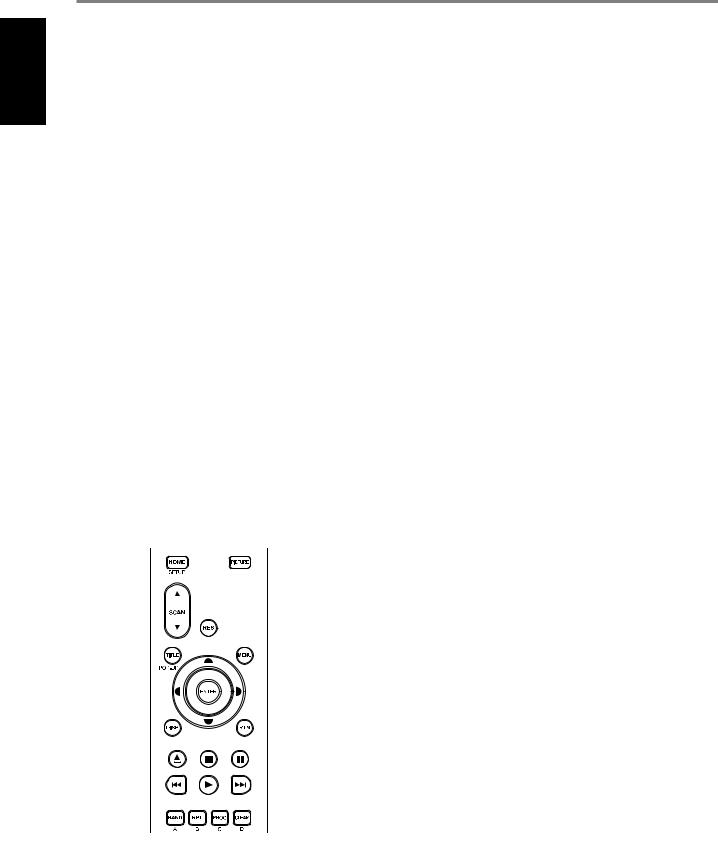
USING THE AVR 4 REMOTE CONTROL
The AVR 4 remote control handset handles the key functions of the T 758. The AVR 4 can also be used to directly command other NAD products that respond to applicable common remote control codes. This includes other NAD Stereo Receiver, Integrated Amplifier and Preamplifier models. It has additional controls to remotely operate NAD Blu-ray Disc Players, AM/FM Tuners and dedicated AM/ FM/DB Tuners. It will operate up to a distance of 23ft (7m). Alkaline batteries are recommended for maximum operating life. Two AA batteries should be fitted in the battery compartment at the rear of
the Remote Control handset. When replacing batteries, check that they have been put in the right way round, as indicated on the base of the battery compartment.
NOTE
The remote control handset supplied with the T 758 is of a universal NAD type, designed to operate several NAD models. Some buttons are applicable only to specific NAD models. Contact your dealer or NAD audio specialist for assistance.
1ON, OFF
The AVR 4 remote has a separate ON and OFF button.
•Press ON button to switch the T 758 from Standby to operating mode. Press OFF button to switch the T 758 to Standby mode.
2DEVICE SELECTOR
A Device Selector button determines only what component the AVR 4 will command; it does not perform any function on the T 758.
•Press desired Device Selector button for the applicable buttons to be directed to a “page” of commands relevant to the selected device. Upon selecting a Device, you can now press the corresponding AVR 4 control buttons applicable for the selected Device.
3INPUT SELECTORS
1
|
2 |
3, 4 |
7 |
|
6 |
5 |
|
8 |
10 |
9 |
11 |
12
13
15
14 |
16 |
Refer to the corresponding labels printed in the remote control faceplate and their respective assigned buttons to make use of these functions.
•Set the DEVICE SELECTOR to “AMP” in order to gain access to these buttons.
•INPUT 1, INPUT 2 up to INPUT 7 corresponds to T 758’s Source 1, Source 2 up to Source 7. Select FRONT to select Front Input and MP for Front Audio MP input.
4NUMERIC KEYS
The numeric keys allow for direct input of tracks for CD players and direct channel/preset access for tuners and receivers.
5A/V PSET
In combination with the numeric keys, press a Preset number from 1 to 5 as referenced to A/V Presets settings. Note that the Preset settings can be configured via the A/V Presets menu.
6DIMMER
•Reduce or restore VFD brightness.
•Depending on the NAD model, the brightness of the front panel display will vary when you toggle this button.
•Use with NAD T 758 and other compatible NAD Stereo Receiver, Tuner and CD Player models.
7TEST
Initiate speaker TEST mode while at the Speaker Levels section of the Speaker Setup menu.
8MUTE
•Temporarily mutes audio output or restores audio from mute mode.
•MUTE mode is indicated by flashing Standby LED indicator for NAD Integrated Amplifiers or “Mute” shown in the VFD of NAD Receivers.
•Adjusting the volume level via the AVR 4 or the front panel volume knob will automatically release the mute function.
9SOURCE 5/6
•Toggle to select desired Source.
10SURR
Select desired listening or surround mode.
ENGLISH
11
ENGLISH
IDENTIFICATION OF CONTROLS
AVR 4 REMOTE CONTROL
11VOL 5/6
•Increase or decrease loudness level. Release the button when desired level is reached.
•The VFD on the front panel will indicate the level set. For NAD Receivers, the VFD will also show “Volume Up” or “Volume Down” or “Volume: _ _ dB” (_ _ indicates the numerical dB level) while pressing AVR 4’s [VOL 5/6 ] buttons.
12A/S/D/F, ENTER
Select an item in a menu.
13SLEEP
Switch off the NAD Receiver or Tuner after a preset number of minutes.
SLEEP MODE
The Sleep Mode timer will switch the T 758 to Standby mode automatically after a preset number of minutes. Pressing the AVR 4’s [SLEEP] button once will display the current setting of the sleep time mode or remaining time before the T 758 goes to standby mode. Pressing the AVR 4’s [SLEEP] button a second time within a 3-second period will change the sleep time mode to the next sleep time setting. Each consecutive press increases the sleep time in 15-minute increments from 15 to 90 minutes. To cancel the sleep mode, continue pressing the AVR 4’s [SLEEP] button until “Sleep Off” is displayed on the VFD. Switching the T 758 to standby mode from either the AVR 4’s OFF or the T 758’s Standby button will also cancel the sleep mode.
14EQ
Enable or disable Equalization (EQ) effect as set up at Auto Calibration. This is not applicable to T 758.
15TONE
Adjust Treble or Bass level. Toggle [TONE] and then use [ D/F ] buttons to set up values.
16L.NITE
Set Dynamic Range Control (DRC) level. Toggle [L.NITE] to select either DTS or Dolby DRC setting and then use [ D/F ] buttons to set up DRC level. This is not applicable to T 758.
BD PLAYER CONTROL (use with compatible NAD Blu-ray Disc Player models)
Set the DEVICE SELECTOR to “BD” in order to gain access to these buttons. Some of the control buttons below are applicable only to specific NAD Blu-ray Disc Players; check the owner’s manual of your NAD model for control button compatibility. You can also load the applicable NAD code library to this device so that it can be made compatible with your other NAD equipment. Refer to the section below about “LIBRARY” on how to load a NAD code library.
HOME: Display or exit HOME menu.
PICTURE: Display or exit the Picture Mode menu. SCAN [5/6]: Fast reverse/forward search.
RES: Set output resolution of HDMI and Component Video output. TITLE/POP-UP: Display DVD title menu or BD-ROM pop-up menu, if available. MENU: Access disc menu, if available.
D/F/A/S: Select an item in a menu. Select desired track, chapter, file or folder. In some applications, one has to press [ENTER] to complete the selection.
ENTER: Confirm selected option, item or menu.
DISP: Show playback time and other display information. RTN: Exit from a menu window.
[k]: Open or close disc tray. [g]: Stop playback.
[;]: Pause playback temporarily.
[9]: Go to the beginning of current or previous track, chapter or file. [4]: Start playback.
[0]: Go to next track, chapter or file. RAND: Play tracks/files in random order. RPT: Repeat track, chapter, file or whole disc. PROG: Enter or exit program mode. CLEAR: Delete programmed track/file.
A,B,C,D: Navigate or select BD-ROM menu, if applicable.
12
IDENTIFICATION OF CONTROLS
AVR 4 REMOTE CONTROL
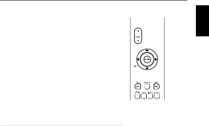
TUNER CONTROL (use with T 758 tuner section and other compatible NAD Receiver, AM/FM/ DAB Tuner models)
Set the DEVICE SELECTOR to “TUN” in order to gain access to these buttons. Refer to the corresponding labels printed in the remote control faceplate and their respective assigned buttons to make use of these functions. Some of the control buttons below are applicable only to specific NAD Receiver
or Tuner models; check the owner’s manual of your NAD Receiver or Tuner for control button compatibility. You can also load the applicable NAD code library to this device so that it can be made compatible with your other NAD equipment. Refer to the section below about “LIBRARY” on how to load a NAD code library.
SCAN [ 5/6 ] or [ A/S]: Tune forward or backwards.
INFO: Repeatedly pressing this button will show information as supplied by the current radio station. The applicable display contents include related DAB display information and RDS broadcast data.
PRESET [ 9/0 ] or [ D/F]: Step up or down Preset numbers.
[ A/S]: In combination with [TUNER MODE] or other compatible buttons, select through applicable DAB menu options.
ENTER: Select Preset or Tune mode at AM/FM band. Display signal strength at DAB mode. AM/FM/DB: Select DAB, FM or AM band, as applicable.
TUNER MODE: In FM mode, toggle between “FM Mute On” and “FM Mute Off”. In DAB mode, use the [TUNER MODE] button in combination with [ A/S/D/F ] and [ENTER] buttons to activate DAB menu options.
BLEND: Engage or disengage BLEND feature. This is not applicable to T 758. MEMORY: Save current station to a Preset number.
DELETE: Delete selected Preset number.
NOTE
For iPod player-specific control buttons, please refer to “CONTROL FEATURES AND SETTINGS” under “OPERATION - LISTENING TO YOUR iPod PLAYER”.
ENGLISH
13
Loading...