


 ® T 755
AV Surround Sound Receiver
Owner’s Manual
Manuel d’Installation
Manual del Usuario
Manuale delle Istruzioni
ENGLISH
FRANÇAIS
ESPAÑOL
ITALIANO
SVENSKA NEDERLANDS DEUTSCH
РУССКИЙ

ENGLISH
FRANÇAIS
ESPAÑOL
ITALIANO
SVENSKA NEDERLANDS DEUTSCH
РУССКИЙ
IMPORTANT SAFETY INSTRUCTIONS
1.Read instructions - All the safety and operating instructions should be read before the product is operated.
2.Retain instructions - The safety and operating instructions should be retained for future reference.
3.Heed Warnings - All warnings on the product and in the operating instructions should be adhered to.
4.Follow Instructions - All operating and use instructions should be followed.
5.Cleaning - Unplug this product from the wall outlet before cleaning. Do not use liquid cleaners or aerosol cleaners. Use a damp cloth for cleaning.
6.Attachments - Do not use attachments not recommended by the product manufacturer as they may cause hazards.
7.Water and Moisture - Do not use this product near water-for example, near a bath tub, wash bowl, kitchen sink, or laundry tub; in a wet basement; or near a swimming pool; and the like.
8.Accessories - Do not place this product on an unstable cart, stand, tripod, bracket, or table. The product may fall, causing serious injury to a child or adult and serious damage to the product. Use only with a
cart, stand, tripod, bracket, or table recommended by the manufacturer, or sold with the product. Any mounting of the product should follow the manufacturer’s instructions, and should use a mounting accessory recommended by the manufacturer.
9.  Cart - A product and cart combination should be moved
with care. Quick stops, excessive force, and uneven surfaces may cause the product and cart combination to overturn.
10.Ventilation - Slots and openings in the cabinet are provided for ventilation to ensure reliable operation of the product and to protect it from overheating. These openings must not be blocked or covered. The openings should never be blocked by placing the product on a bed, sofa, rug, or other similar surface. This product should not be placed in a built-in installation such as a bookcase or rack unless proper ventilation is provided or the manufacturer’s instructions have been adhered to.
11.Power Sources - This product should be operated only from the type of power source indicated on the marking label and connected to
a MAINS socket outlet with a protective earthing connection. If you are not sure of the type of power supply to your home, consult your product dealer or local power company.
12.Power-Cord Protection - Power-supply cords should be routed so that they are not likely to be walked on or pinched by items placed upon or against them, paying particular attention to cords at plugs, convenience receptacles, and the point where they exit from the product.
13.Mains Plug - Where the mains plug or an appliance coupler is used as the disconnect device, the disconnect device shall remain readily operable.
14.Outdoor Antenna Grounding - If an outside antenna or cable system is connected to the product, be sure the antenna or cable system is grounded so as to provide some protection against voltage surges and built-up static charges. Article 810 of the National Electrical Code, ANSI/NFPA 70, provides information with regard to proper grounding of the mast and supporting structure, grounding of the lead-in wire
to an antenna discharge unit, size of grounding conductors, location of antenna discharge unit, connection to grounding electrodes, and requirements for the grounding electrode.
NOTE TO CATV SYSTEM INSTALLER
ThisreminderisprovidedtocalltheCATVsysteminstaller’sattentiontoSection820-40of theNECwhichprovidesguidelinesforpropergroundingand,inparticular,specifiesthat thecablegroundshallbeconnectedtothegroundingsystemofthebuilding,asclose tothepointofcableentryaspractical.
15.Lightning - For added protection for this product during a lightning storm, or when it is left unattended and unused for long periods of time, unplug it from the wall outlet and disconnect the antenna or cable system. This will prevent damage to the product due to lightning and power-line surges.
16.Power Lines - An outside antenna system should not be located in the vicinity of overhead power lines or other electric light or power circuits, or where it can fall into such power lines or circuits. When installing an outside antenna system, extreme care should be taken to keep from touching such power lines or circuits as contact with them might be fatal.
17.Overloading - Do not overload wall outlets, extension cords, or integral convenience receptacles as this can result in a risk of fire or electric shock.
18.Flame Sources - No naked flame sources, such as lighted candles, should be placed on the product.
19.Object and Liquid Entry - Never push objects of any kind into this product through openings as they may touch dangerous voltage points or short-out parts that could result in a fire or electric shock. Never spill liquid of any kind on the product.
20.Headphones - Excessive sound pressure form earphones and headphones can cause hearing loss.
21.Damage Requiring Service - Unplug this product from the wall outlet and refer servicing to qualified service personnel under the following conditions:
a.When the power-supply cord or plug is damaged.
b.If liquid has been spilled, or objects have fallen into the product.
c.If the product has been exposed to rain or water.
d.If the product does not operate normally by following the operating instructions. Adjust only those controls that are covered by the operating instructions as an improper adjustment of other controls may result in damage and will often require extensive work by a qualified technician to restore the product to its normal operation.
e.If the product has been dropped or damaged in any way.
f.When the product exhibits a distinct change in performance-this indicates a need for service.
22.Replacement Parts - When replacement parts are required, be sure the service technician has used replacement parts specified by the manufacturer or have the same characteristics as the original part. Unauthorized substitutions may result in fire, electric shock, or other hazards.
IMPORTANT SAFETY INSTRUCTIONS
23.Battery Disposal - When disposing of used batteries, please comply with governmental regulations or environmental public instruction’s rules that apply in your country or area.
24.Safety Check - Upon completion of any service or repairs to this product, ask the service technician to perform safety checks to determine that the product is in proper operating condition.
25.Wall or Ceiling Mounting - The product should be mounted to a wall or ceiling only as recommended by the manufacturer.
Warning
The lightning flash with arrowhead symbol, within an equilateral triangle, is intended to alert the user to the presence of uninsulated “dangerous voltage” within the product’s enclosure that may be of sufficient magnitude to constitute a risk of electric shock to persons
The exclamation point within an equilateral triangle is intended to alert the user to the presence of important operating
and maintenance (servicing) instructions in the literature accompanying the appliance.
WARNING: TO REDUCE THE RISK OF FIRE OR ELECTRIC SHOCK, DO NOT EXPOSE THIS APPARATUS TO RAIN OR MOISTURE AND OBJECTS FILLED WITH LIQUIDS, SUCH AS VASES, SHOULD NOT BE PLACED ON THIS APPARATUS.
THE EQUIPMENT MUST BE CONNECTED TO AN EARTHED MAINS SOCKETOUTLET.
CAUTION REGARDING PLACEMENT
To maintain proper ventilation, be sure to leave a space around the unit (from the largest outer dimensions including projections) than is equal to, or greater than shown below.
Left and Right Panels: 10 cm Rear Panel: 10 cm
Top Panel: 50 cm
IMPORTANT INFORMATION TO UK CUSTOMERS
DO NOT cut off the mains plug from this equipment. If the plug fitted is not suitable for the power points in your home or the cable is too short to reach a power point, then obtain an appropriate safety approved extension lead or consult your dealer. If nonetheless, the mains plug is cut off, REMOVE THE FUSE and dispose of the PLUG immediately, to avoid possible shock hazard by inadvertent connection to the mains supply. If this product is not provided with a mains plug, or one has to be fitted, then follow the instructions given below:
IMPORTANT
DO NOT make any connection to the larger terminal which is marked with the letter ‘E’ or by the safety earth symbol or colored GREEN or GREEN AND YELLOW. The wires in the mains lead on this product are colored in accordance with the following code:
BLUE - NEUTRAL
BROWN - LIVE
As these colors may not correspond with the colored markings identifying the terminals in your plug, proceed as follows:
•The BLUE wire must be connected to the terminal marked with the letter ‘N’ or colored BLACK.
•The BROWN wire must be connected to the terminal marked with the letter ‘L’ or colored RED
•When replacing the fuse, only a correctly rated and approved type should be used, and be sure to re-fit the fuse cover.
IF IN DOUBT CONSULT A COMPETENT ELECTRICIAN.
This product is manufactured to comply with the radio interference requirements of EEC DIRECTIVE 2004/108/EC.
notes on environmental protection
At the end of its useful life, this product must not be disposed of with regular household waste but must be returned to a collection point for the recycling of electrical and electronic
equipment. The symbol on the product, user’s manual and packaging point this out.
The materials can be reused in accordance with their markings. Through re-use, recycling of raw materials, or other forms of recycling of old products, you are making an important contribution to the protection of our environment.
Your local administrative office can advise you of the responsible waste disposal point.
RECORD YOUR MODEL NUMBER (NOW, WHILE YOU CAN SEE IT)
The model and serial number of your new T 755 are located on the back of the cabinet. For your future convenience, we suggest that you record these numbers here:
Model number : . . . . . . . . . . . . . . . . . . . . . . . . . . . . . . . . . . . . . .
Serial number :. . . . . . . . . . . . . . . . . . . .
NAD is a trademark of NAD Electronics International, a division of Lenbrook Industries Limited Copyright 2008, NAD Electronics International, a division of Lenbrook Industries Limited
ENGLISH
FRANÇAIS
ESPAÑOL
ITALIANO
SVENSKA NEDERLANDS DEUTSCH
РУССКИЙ

ENGLISH
FRANÇAIS
ESPAÑOL
ITALIANO
SVENSKA NEDERLANDS DEUTSCH
РУССКИЙ
INTRODUCTION
TABLE OF CONTENTS
IMPORTANT SAFETY INSTRUCTIONS. . . . . . . . . . . . . . . 2
INTRODUCTION
ABOUT THE T 755 . . . . . . . . . . . . . . . . . . . . . . . . . 5
E.A.R.S. AND DIGITAL SURROUND . . . . . . . . . . . . . . . . . . .5 EASE OF USE. . . . . . . . . . . . . . . . . . . . . . . . . . . . . 5 INTEGRATION . . . . . . . . . . . . . . . . . . . . . . . . . . . . .5 ZONE. . . . . . . . . . . . . . . . . . . . . . . . . . . . . . . . . 5 RS 232. . . . . . . . . . . . . . . . . . . . . . . . . . . . . . . . .5 UPGRADABILITY. . . . . . . . . . . . . . . . . . . . . . . . . . . .5 ABOUT THE HTR 3 SYSTEM REMOTE CONTROL. . . . . . . . . . . . 5
GETTING STARTED. . . . . . . . . . . . . . . . . . . . . . . . . 6
WHAT’S IN THE BOX. . . . . . . . . . . . . . . . . . . . . . . . . .6 CHOOSING A LOCATION . . . . . . . . . . . . . . . . . . . . . . . 6 QUICK START. . . . . . . . . . . . . . . . . . . . . . . . . . . . . 6 DEALING WITH HUM AND NOISE. . . . . . . . . . . . . . . . . . . 6
IDENTIFICATION OF CONTROLS
FRONT PANEL. . . . . . . . . . . . . . . . . . . . . . . . . . . 7 REAR PANEL. . . . . . . . . . . . . . . . . . . . . . . . . . . . 9
OPERATION
USING THE T 755 – MAIN MENU . . . . . . . . . . . . . . . . . .12
ABOUT THE ON-SCREEN DISPLAY (OSD). . . . . . . . . . . . . . . 12 MAIN MENU. . . . . . . . . . . . . . . . . . . . . . . . . . . . . 12 LISTENING MODE . . . . . . . . . . . . . . . . . . . . . . . . . . 12 ADJUSTING LISTENING MODES . . . . . . . . . . . . . . . . . . . 14 DSP OPTIONS . . . . . . . . . . . . . . . . . . . . . . . . . . . . 14 TONE CONTROLS. . . . . . . . . . . . . . . . . . . . . . . . . . 14 ZONE CONTROLS. . . . . . . . . . . . . . . . . . . . . . . . . . . . . . . . . . . . . . . . . . . . . . . . . . . 15
USING THE T 755 –SETUP MENU. . . . . . . . . . . . . . . . . .16
SETUP MENU. . . . . . . . . . . . . . . . . . . . . . . . . . . . 16 SOURCE SETUP . . . . . . . . . . . . . . . . . . . . . . . . . . . 16 SOURCE SETUP (NORMAL VIEW) . . . . . . . . . . . . . . . . . . 16 SOURCE SETUP (TABLE VIEW). . . . . . . . . . . . . . . . . . . . 18 iPod SETUP. . . . . . . . . . . . . . . . . . . . . . . . . . . . . 19 SPEAKER SETUP. . . . . . . . . . . . . . . . . . . . . . . . . . . 19 Audyssey Setup . . . . . . . . . . . . . . . . . . . . . . . . . . 19 SPEAKER CONFIGURATION. . . . . . . . . . . . . . . . . . . . . 20 SPEAKER LEVELS. . . . . . . . . . . . . . . . . . . . . . . . . . . 22 SPEAKER DISTANCE . . . . . . . . . . . . . . . . . . . . . . . . . 23 ADJUSTING THE VOLUME . . . . . . . . . . . . . . . . . . . . . . 23 ADJUSTING CHANNEL LEVELS “ON THE FLY”. . . . . . . . . . . . . 24 ZONE SETUP . . . . . . . . . . . . . . . . . . . . . . . . . . . . 24 TRIGGER SETUP . . . . . . . . . . . . . . . . . . . . . . . . . . . 24
THANK YOU FOR CHOOSING NAD.
The T 755 A/V Receiver is a technologically advanced and highly capable product — yet we have invested great effort in making it simple and easy to use. The T 755 delivers a range of genuinely useful options for surround sound and stereo listening, using powerful digital signal processing and superbly accurate digital-audio circuitry. However, we have also been careful to ensure that the T 755 is as musically transparent and spatially accurate as possible, incorporating much of what we’ve learned from
a quarter century’s experience designing audio and home-theater components. As with all our products, NAD’s “Music First” design philosophy guided the T 755’s design, such that it can confidently promise you both state-of-the-art surround home-theater and audiophile-quality music listening for years to come.
LISTENING MODE SETUP. . . . . . . . . . . . . . . . . . . . . . |
25 |
DOLBY SETUP. . . . . . . . . . . . . . . . . . . . . . . . . . . . |
27 |
DTS SETUP . . . . . . . . . . . . . . . . . . . . . . . . . . . . . |
27 |
DTS SURROUND MODES. . . . . . . . . . . . . . . . . . . . . . |
27 |
ENHANCED STEREO. . . . . . . . . . . . . . . . . . . . . . . . . |
28 |
DISPLAY SETUP. . . . . . . . . . . . . . . . . . . . . . . . . . . |
28 |
A/V PRESETS. . . . . . . . . . . . . . . . . . . . . . . . . . . . . |
29 |
USING THE T 755 – AM/FM/DB/iPod. . . . . . . . . . . . . . . . |
30 |
LISTENING TO RADIO. . . . . . . . . . . . . . . . . . . . . . . . |
30 |
ABOUT USER NAMES. . . . . . . . . . . . . . . . . . . . . . . . |
30 |
ABOUT RDS . . . . . . . . . . . . . . . . . . . . . . . . . . . . . |
31 |
ABOUT XM RADIO. . . . . . . . . . . . . . . . . . . . . . . . . . |
31 |
CONNECTING THE XM ANTENNA . . . . . . . . . . . . . . . . . . |
31 |
ABOUT DAB RADIO. . . . . . . . . . . . . . . . . . . . . . . . . |
31 |
CONNECTING THE DAB MODULE . . . . . . . . . . . . . . . . . . |
31 |
DAB OPERATION . . . . . . . . . . . . . . . . . . . . . . . . . . |
32 |
SERVICE LIST . . . . . . . . . . . . . . . . . . . . . . . . . . . . |
32 |
DAB TUNER MODE . . . . . . . . . . . . . . . . . . . . . . . . . |
32 |
STATION ORDER. . . . . . . . . . . . . . . . . . . . . . . . . . . |
32 |
DRC. . . . . . . . . . . . . . . . . . . . . . . . . . . . . . . . . |
32 |
MANUAL SCAN. . . . . . . . . . . . . . . . . . . . . . . . . . . |
33 |
PRUNE LIST. . . . . . . . . . . . . . . . . . . . . . . . . . . . . |
33 |
RESET . . . . . . . . . . . . . . . . . . . . . . . . . . . . . . . . |
33 |
INFORMATION SETTINGS. . . . . . . . . . . . . . . . . . . . . . |
33 |
ABOUT THE iPod INPUT FEATURE. . . . . . . . . . . . . . . . . . |
33 |
CONNECTING THE OPTIONAL “NAD IPD 1 Dock with |
|
iPod” And iPod PLAYER TO THE T 755. . . . . . . . . . . . . . . . |
34 |
USING THE HTR 3 REMOTE CONTROL . . . . . . . . . . . . . . . |
35 |
Specifications. . . . . . . . . . . . . . . . . . . . . . . . . . . |
35 |
Controlling the T 755. . . . . . . . . . . . . . . . . . . . . . |
35 |
Learning Codes from other Remotes. . . . . . . . . . . . . |
36 |
Punch Through. . . . . . . . . . . . . . . . . . . . . . . . . . |
36 |
Copy a Command from another key. . . . . . . . . . . . . . |
36 |
Macro Commands. . . . . . . . . . . . . . . . . . . . . . . . |
36 |
Button Illumination Timeout. . . . . . . . . . . . . . . . . . |
37 |
Factory Reset. . . . . . . . . . . . . . . . . . . . . . . . . . . |
37 |
Delete Mode. . . . . . . . . . . . . . . . . . . . . . . . . . . . |
37 |
Loading Code-Libraries. . . . . . . . . . . . . . . . . . . . . |
38 |
Search Mode. . . . . . . . . . . . . . . . . . . . . . . . . . . |
38 |
Checking Code-Library Number. . . . . . . . . . . . . . . . . |
38 |
USING THE ZR 4 REMOTE CONTROL. . . . . . . . . . . . . . . . . |
39 |
REFERENCE
TROUBLESHOOTING. . . . . . . . . . . . . . . . . . . . . . . 40 SPECIFICATIONS. . . . . . . . . . . . . . . . . . . . . . . . . 41
We encourage you to take a few minutes now to read right through this manual. Investing a little time here at the outset might save you a good deal of time later, and is by far the best way to ensure that you make the most of your investment in the NAD T 755, and get the most from this powerful and flexible home-theater component.
One more thing: We urge you to register your T 755 ownership on the NAD Worldwide Web site:
<http://NADelectronics.com/warranty>
For warranty information contact your local distributor.

INTRODUCTION
ABOUT THE T 755
Though the T 755 is among the most technically sophisticated A/V receiver, we worked hard to make it one of the most musically transparent hometheater components available as well; this is what we mean by NAD’s “Music First” design philosophy. Here are just few examples:
•The T 755 uses NAD’s proprietary Power Drive™ amplifier technology for all channels to preserve accurate, linear reproduction regardless of the loudspeaker. This uniquely efficient power-supply topology provides the real-world benefits of high dynamic power that remains uncompromised by low-impedance speakers. The result is dynamic, detailed,”un-receiver-like” sound in stereo and multi-channel modes alike. NAD’s exclusive Soft Clipping™ circuitry further enhances sound quality and dynamic potential.
•High-performance components used throughout the receiver’s analog audio circuits to maximize quality from all sources, including multichannel analog sources such as DVD-Audio and SACD.
•Preamp output (all channels) and main-amp input jacks make potential expansion as flexible as possible.
•Zone pre-amp and video feed with assignable 12 V DC trigger control.
•A Second set of Speaker terminals (Speakers B) for remote listening.
•An RS-232 port for advanced zone control and software update through a Windows® compatible PC.
•Gold-surfaced connectors are employed throughout to ensure maximum signal integrity.
E.A.R.S. AND DIGITAL SURROUND
A key element of the T 755’s unique musical aptitude is NAD’s proprietary Enhanced Ambience Recovery System (EARS). In sharp contrast to many “ambience-synthesis” music-surround modes, EARS exploits the T 755’s substantial DSP power to route the ambient content that is “encrypted” in virtually all natural-acoustic recordings to the appropriate main, center and surround speakers, without resorting to artificially generated reflections
or regeneration. EARS’ natural ambience yields a subtle but exceptionally effective surround mode that naturally enhances the spatial presentation in a fashion suitable for serious music listening.
INTEGRATION
The T 755 A/V Receiver offers extensive, flexible system-integration options through its configurable DC trigger outputs and input, and its standardprotocol IR communications links. The DC trigger outputs can be assigned to Main, Zone and Source Setup locations.
ZONE
The T 755 A/V Receiver is equipped with a configurable Zone 2 that makes full use of video and pre-amp level audio outputs. The ZR 4 remote control will allow you complete access to Zone 2 applications including access to volume On/Off and all sources inputs.
RS 232
Flexible system configuration is possible with the RS-232 interface and NAD’s proprietary Windows® compatible software. We are also certified partners with AMX and Crestron and fully support these external devices.
This interface allows complete remote control of the T 755 from any remote location via the PC. Complete remote control functionality is available to the user by interface software. See your NAD audio specialist for further information.
UPGRADABILITY
The T 755 A/V Receiver permits flexible system growth via individually accessible pre-out and main-in jacks for all channels. We have made the more likely scenario of software upgrades easy to accomplish via the high speed RS-232 port on the rear panel of the T 755. Owners who register their T 755 on our international web site www.NADelectronics.com will be advised of updates. Some of these may be free of charge, and some may require royalty payments depending on the type of upgrade. The advanced user will be able to perform these upgrades by downloading files from our web site, via e-mail and installing them by connecting the T 755 to a PC. Alternatively the dealer from whom you purchased your T 755 should be able to assist in performing these upgrades.
ABOUT THE HTR 3 SYSTEM REMOTE CONTROL
Dolby Pro Logic IIx Music and DTS Neo:6 Music modes can also create enjoyable experience from 2-channel sources.
On the digital side, the T 755 combines extraordinarily high-speed DSP processing employing one of the most advanced high-speed DSP “engines” available, with fully 24-bit, 192 kHz-sampling-capable D/A converters for
all channels. A single, high-precision master clock synchronizes all digital circuits to eliminate the timing errors (jitter) that otherwise compromise sonics. The result is legitimately state-of-the-art surround decoding from
Dolby Digital and DTS sources, and 6.1/7.1-channel reproduction, with genuinely superior sound quality in all modes.
EASE OF USE
Despite the effort NAD has invested in the T 755 A/V Receiver’s sonic performance, we expended no less in making it powerfully easy to use. Its design is uniquely simple for so sophisticated a component, and the
HTR 3 universal remote control is equally understandable, as are the T 755’s own front-panel and on-screen displays. Its simple yet powerful system
of “presets” permits you to fine-tune your listening setup for different conditions, sources, or listeners, and to recall these multiple parameters with a single key press.
Packed with your T 755 is the NAD HTR 3 remote control, a full-system remote especially designed for easy use and understanding. Be sure to read the section “Using the HTR 3 Remote Control”, to familiarize yourself with the remote’s layout and operations before proceeding to setup your T 755. You may opt to use your HTR 3 as your primary way to command your entire AV system. The HTR 3 can be employed to operate additional NAD or other-brand components such as a DVD/CD player, television, satellite/ HDTV tuner, VCR, or virtually anything else that operates via standard infrared remote.
ENGLISH
FRANÇAIS
ESPAÑOL
ITALIANO
SVENSKA NEDERLANDS DEUTSCH
РУССКИЙ

ENGLISH
FRANÇAIS
ESPAÑOL
ITALIANO
SVENSKA NEDERLANDS DEUTSCH
РУССКИЙ
INTRODUCTION
GETTING STARTED
WHAT’S IN THE BOX
Packed with your T 755 A/V Receiver you will find
•An AM loop antenna.
•A FM ribbon-wire antenna with balun.
•A removable AC cable (if you wish, any IEC-standard AC cable of suitable wattage may be substituted).
•The HTR 3 remote control with 4 (four) AAA batteries.
•The ZR 4 zone remote control with 3V CR2025 battery.
•This owner’s manual.
SAVE THE PACKAGING
Please save the box and all of the packaging in which your T 755 arrived. Should you move or otherwise need to transport your T 755, this is by far the safest container in which to do so. We’ve seen too many otherwise perfect components damaged in transit for lack of a proper shipping carton, so please: Save that box!
CHOOSING A LOCATION
Choose a location that is well ventilated (with at least several inches to both sides and behind), and that will provide a clear line of sight, within 23 feet/7 meters, between the T 755’s front panel and your primary listening/viewing position—this will ensure reliable infrared remote control communications. The T 755 generates a modest amount of heat, but nothing that should trouble adjacent components.
It is especially important that sufficient ventilation be provided. If you are contemplating on locating the T 755 within a cabinet or other furniture, consult your NAD audio/video specialist for advice on providing adequate airflow.
QUICK START
Packed with your T 755 is a Quick Start Guide that will guide you through typical setup configurations in combination with your ancillary devices. The Quick Start Guide also features the contents of your T 755 package as well as start up procedures.
The T 755 is defaulted to the following settings:
DEALING WITH HUM AND NOISE
Hum and noise may sometimes prove a challenge in complex, multichannel audio systems. Note these considerations to help prevent hum and noise problems:
•Power all your system’s audio component from AC outlets originating from the same circuit of your house wiring. As far as possible, power all audio components from the same outlet, or adjacent outlets on the same circuit. It may be useful to power video displays (and computers!) from outlets on another circuit, especially if that circuit is supplied from the other “leg” of the house wiring.
•Do not bundle analog audio cables with AC power cables, or with coaxial digital-audio cables. It is best if they cross at right angles if they must be in close proximity.
•Employ high-quality, well-shielded audio cable throughout, and ensure that all connections are secure.
•A pencil-eraser can be used to burnish copperand gold-plated contacts to ensure good, low-resistance contact; specialized contactcleaners can also be useful. Avoid unnecessary unplugging and re-plugging since the gold (or copper) contact plating of typical cable connectors, even very high-quality ones, is very thin and easily worn.
Track down hum/noise problems one component at a time, working backwards from the A/V Receiver. That is
1Connect the speakers to the A/V Receiver only, and check for hum.
2Then connect one component only (a CD player, for example) alone, with no other components connected and check for hum.
3Connect additional components, one at a time, to the A/V Receiver and check for hum.
At each stage, if hum/noise appears, examine the audio cabling and ACpower routing of the new component. In some cases, moving the new component’s AC cord to a different outlet, or installing a ground-lift (3-to-2- prong adapter) on its power cord, will eliminate the hum.
Source |
Audio Input |
Video Input |
Video Output |
|
|
|
|
|
|
Source 1 |
Optical 1/ |
Component Video 1 IN |
Component Video |
|
Audio 1 IN |
OUT |
|||
|
|
|||
Source 2 |
Optical 2 IN/ |
HDMI 2 IN |
HDMI Monitor OUT |
|
Audio 2 IN/ |
||||
|
|
|
||
Source 3 |
Coaxial 3 IN / |
S Video 3 IN |
S-Video Monitor OUT |
|
Audio 3 IN |
||||
|
|
|
||
Source 4 |
Audio 4 IN |
Video 4 IN |
Video Monitor OUT |
|
|
|
|
|
|
iPod |
Audio 5 IN |
S-Video 5 IN |
S-Video Monitor OUT |
|
|
|
|
|
|
Source 7 |
7.1 Input |
Component Video 3 IN |
Component Video |
|
OUT |
||||
|
|
|
||
Front |
Audio Front |
|
|
|
Input/Optical |
S-Video Front IN |
S-Video Monitor OUT |
||
Input |
||||
Front Input |
|
|
||
|
|
|
||
Media |
Audio MP input |
|
|
|
Player |
|
|
||
|
|
|
||
Tuner |
|
|
|
To modify the above default settings and for a better understanding of source setting and combinations, please refer to the section on ‘Source Setup’ of the Setup Menu discussion.
NOTES
•Digital input will always take precedence over analog audio input even if both are present.
•The T 755 is optimized for Component Video Output. Composite video and S-video sources may be viewed in their native format or via Component Video OUT.
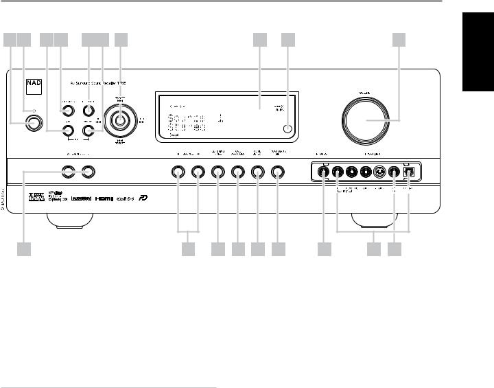
IDENTIFICATION OF CONTROLS
FRONT PANEL
1 |
2 |
3 |
4 |
5 |
6 |
7 |
8 |
9 |
10 |
ENGLISH |
|
|||
|
|
|
FRANÇAIS |
|
|
|
|
|
|
|
|
ESPAÑOL |
11 |
12 |
13 |
14 |
15 |
16 |
17 |
18 |
19 |
1POWER BUTTON: Press this button or the HTR 3 remote’s [ON] button to switch ON the T 755. The Standby LED indicator will turn from amber to blue and illuminate the VFD. Pressing the power button again turns the unit back to standby mode.
The T 755 can also be switched ON from standby mode by pressing any of the front panel buttons. When both Main and Zone 2 are ON, press and hold this button for more than five seconds to place them at standby mode.
NOTES
•The rear panel POWER switch must be in the ON position for the Power button to activate.
•If Auto Trigger IN at Trigger Setup menu is assigned to “Main” or “All” and the TRIGGER switch is set to “AUTO” mode, the Power button in the front panel as well as the corresponding ON/OFF function keys in the HTR 3 remote control will be disabled effectively handing this function to an external controller. Switch TRIGGER to “OFF” to maintain normal power ON/OFF function procedures. (See section also about “TRIGGER SETUP” under the “SETUP MENU” discussions.)
2STANDBY LED: This indicator will light up amber when the T 755 is in standby state. When the T 755 main or zone 2 are in the ON state, this indicator will illuminate blue. In the unlikely event that the T 755 switches to protection state, then this indicator will illuminate red.
When an infrared command from the HTR 3 is received, this indicator will also flash momentarily.
3INFO: Repeatedly toggle this button (press/hold first if in Tuner mode and then toggle) to display both at the Vacuum Fluorescent Display (VFD) and On-Screen Display (OSD) the following – Current Source, Volume level, Listening mode, Audio Source Format, and active Zone 2 with corresponding Source Input. While at Tuner mode, toggle this button to cycle through RDS name and RDS text.
4AM/FM/DB: Toggle this button to select either AM, FM, DAB (Europe version) or XM (North America version) tuner functions.
5TUNER MODE: In FM mode, this button will toggle between FM Stereo and FM mono. Select FM Mono (FM stereo and FM Mute icons at VFD are extinguished) for stations that have too much interference or are too weak. In DAB (European version only) or XM (North America version only) radio, this button enables the digital radio menus in conjunction with the Navigation button and Enter buttons.
6MEMORY: Press this button to store tuned AM, FM and digital radio stations to the T 755’s 40 preset-memory locations. One can store a mix of any AM, FM and digital radio stations to the 40 available presets.
7NAVIGATION and ENTER buttons: These buttons are used to
navigate the T 755 OSD, Tune Forward [ ] and Tune Backward [
 ], Preset Forward [
 ] and Preset Reverse [
 ] as well as navigation of DAB (European version), XM (North American version) tuner functions and iPod. The middle round button is designated as “ENTER” button; this is normally pressed to complete a selection, procedure, sequence or other applicable functions.
8VACUUM FLUORESCENT DISPLAY (VFD): Provide visual information on all important modes of the T 755 as well as the settings and functions for both Main and Zone 2 locations.
9REMOTE SENSOR: Point the HTR 3 remote control at the remote sensor and press the buttons. Do not expose the remote sensor of the T 755 to a strong light source such as direct sunlight or illumination. If you do so, you may not be able to operate the T 755 with the remote control.
Distance: About 23ft (7m) from the front of the remote sensor. Angle: About 30o in each direction of the front of the remote sensor.
10VOLUME: Use this control to adjust the volume level of the main speakers. The default volume level is -20dB. The VOLUME knob is also used to increment/ decrement other adjustable parameters like Tone Controls.
ITALIANO
SVENSKA NEDERLANDS DEUTSCH
РУССКИЙ

ENGLISH
FRANÇAIS
ESPAÑOL
ITALIANO
SVENSKA NEDERLANDS DEUTSCH
РУССКИЙ
IDENTIFICATION OF CONTROLS
FRONT PANEL
11A SPEAKERS B: Press either speaker A or B or both to select the set of speakers you wish to listen to. Speaker A is the main set of 5 multichannel and surround speakers. Speaker B is an auxiliary set for remote locations such as other rooms of your home. For Speaker B selection, all surround sound sources are downmixed to stereo.
Combining Speaker A and Speaker B (SPEAKERS A + B) will also result to the source being downmixed to stereo.
12[ ] SOURCE [
 ] : Press these buttons to toggle through the input selections – Source 1, Source 2, Source 3, Source 4, iPod, Source 7, Front Input, Media Player and Tuner. More Sources could be directly recalled through these buttons upon enabling them at the Setup Menu (See the section “SOURCE SETUP” at Setup Menu discussion).
13LISTENING MODE: Use to step through the T 755’s Listening mode as discussed in the section “LISTENING MODE”. Depending on the format of the currently selected input (digital or analog, stereo or multichannel), various listening modes are available.
14TONE CONTROLS: Press to adjust TREBLE control using the VOLUME knob over a ± 10dB range. Press again to adjust BASS control. See also section about “TONE CONTROLS” under “MAIN MENU” discussions.
15TONE DEFEAT: Tone Controls are enabled or disabled by pressing this button. Tone controls are bypassed at “Tone Defeat” while at “Tone Active”; the tone controls are enabled again. See also section about “TONE CONTROLS” under “MAIN MENU” discussions.
16FRONT INPUT/MP: Use this button to directly select Front Input and Media Player. Toggle button to switch between Front Input and Media Player input.
17PHONES: Accepts stereo headphone using a standard 1/4-inch stereo phone plug (use a suitable adapter for headphones equipped with a smaller plug). Plugging in headphones will automatically switch the
T 755 to Stereo, Stereo Downmix or Analog Bypass modes.
18FRONT INPUT jacks: Use these convenience jacks for occasional sources such as a camcorder, tape player, video game console, any analog audio or optical digital audio and composite or S-Video video sources. If your source has a single audio out jack only or is marked “Mono output”, plug this into the T 755’s Front “R (Mono)” input. On the other hand, if your source has two output jacks indicative of stereo output, insert both jacks into the T 755’s corresponding Front “L” and “R (Mono)” input to achieve stereo output as well.
19MP/MIC input: Connect your MP3’s standard stereo phone jack to this input. This is the same input where Audyssey microphone jack is connected. See also discussion about “AUDYSSEY SETUP”.

IDENTIFICATION OF CONTROLS
REAR PANEL
1 |
2 |
3 |
4 |
5 |
|
|
|
|
|
|
|
|
|
|
|
|
|
|
|
|
|
|
|
|
|
|
|
|
|
|
|
|
|
|
|
|
|
|
|
|
|
|
|
|
|
|
|
|
|
|
|
|
|
|
|
|
|
|
|
|
|
|
|
|
|
|
|
|
|
|
|
|
|
|
|
|
|
|
|
|
|
|
|
|
|
|
|
|
|
|
|
|
|
|
|
|
|
|
|
|
|
|
|
|
|
|
|
|
|
|
|
|
|
|
|
|
|
|
|
|
|
|
|
|
|
|
|
|
|
|
|
|
|
|
|
|
|
|
|
|
|
|
|
|
|
|
|
|
|
|
|
|
|
|
|
|
|
|
9 |
|
|
10 |
|
11 |
|
12 |
|
|||||
|
|
|
|
|
|
|
|
|
|
|
|
|
|
6 |
7 |
8 |
13 |
14 |
15 |
16 |
17 |
18 |
19 |
20 |
ATTENTION!
Please make sure that the T 755 is powered off or unplugged before making any connections. It is also advisable to power-down or unplug all associated components while making or breaking any signal or AC power connections.
1IR IN/OUT: These mini-jacks accept and output remote-controlled codes in electrical format, using industry-standard protocols, for use with “IR-repeater” and multi-room systems and related technologies.
IR IN : This input is connected to the output of an IR (infrared) repeater (Xantech or similar) or the IR output of another component to allow control of the T 755 from a remote location.
IR OUT 2 : When connected to the IR IN of ancillary equipment, direct the ancillary equipment’s own remote control to the T 755’s infrared receiver to command or control the linked unit.
IR IN and IR OUT 3 : Connect the T 755’s IR IN to the IR OUT of ancillary equipment. Connect also the T 755’s IR OUT 3 to another equipment with IR IN feature. With this setup, the T 755 acts as an “IR-repeater” allowing the equipment connected to the T 755’ s IR IN control or command of the other equipment linked to the T 755’s IR OUT 3.
IR OUT 1 : In conjunction with IR IN, IR OUT 1 can be used as an “IRrepeater” just like the IR OUT 3 as described above. It can also stand alone as an IR OUT similar to that of IR OUT 2 function.
All NAD products with IR IN/IR OUT features are fully compatible with the T 755. For non-NAD models, please check with your other product’s service specialists as to their compatibility to the T 755’s IR features.
2+12 V TRIGGER OUT: There are three configurable +12V TRIGGER OUTPUT. Use a 3.5mm mini-jack connector to pass +12 volts at a maximum current of 200 milliamps to auxiliary equipment such as a multichannel amplifier or subwoofer. The centre conductor (hot) of the 3.5mm jack is the control signal. The outside conductor (shield) is the ground return-path.
TRIGGER IN accepts 12V Trigger output of compatible components such as power controllers and home automation devices.
TRIGGER OFF/AUTO. When at AUTO position, the T 755 selects the 12V Trigger Input to turn ON (if so assigned at the “Trigger Setup” menu) and
at the same time disables the HTR 3 and ON/OFF function of the front panel. When set to [OFF] position, the trigger input is disabled.
See discussion on “TRIGGER SETUP” at the “SETUP MENU” literature for guidelines on how to configure TRIGGER IN/OUT.
WARNING
If Auto Trigger IN at Trigger Setup menu is assigned to “Main” or “All” and the TRIGGER switch is set to “AUTO” mode, the Power button in the front panel as well as the corresponding ON/OFF function keys in the HTR 3 remote control will be disabled effectively handing this function to an external controller. Switch TRIGGER to”OFF” to maintain normal power ON/OFF function procedures.
3SOFT CLIPPING: Enables NAD’s proprietary Soft Clipping circuitry on all channels. At [ON] position, Soft Clipping gently limits the output of the T 755 to minimize audible distortion should the A/V Receiver be over-driven. Soft Clipping may simply be left ON at all times to reduce the likelihood of audible distortion from excessive volume settings. However, for critical listening and to preserve optimum dynamics, you may wish to defeat it by setting this switch OFF.
4FM, AM ANTENNA INPUT: The supplied wire “dipole” FM antenna will connect to the FM connector using the supplied “balun” adapter. It will usually work best when mounted on a vertical surface such as a wall, with arms fully outstretched forming a horizontal “T” perpendicular to the origin point of the signal.
Connect the supplied AM loop antenna to these terminals. If an external AM antenna is used, make connections to the AM and GND terminals in accordance with the instructions supplied with the antenna. See also section about “LISTENING TO RADIO”.
ENGLISH
FRANÇAIS
ESPAÑOL
ITALIANO
SVENSKA NEDERLANDS DEUTSCH
РУССКИЙ

ENGLISH
FRANÇAIS
ESPAÑOL
ITALIANO
SVENSKA NEDERLANDS DEUTSCH
РУССКИЙ
IDENTIFICATION OF CONTROLS
REAR PANEL
5XM MODULE INPUT (North America version only): Connect XM radio cable to this socket. Follow the instructions that came with your XM radio. With XM radio, there are more than 100 channels of music, news, sports, comedy, talk and entertainment. You will find that the coverage is continent wide. The music quality is digital with many commercial-free music channels.
NOTES
Questions? Visit www.xmradio.com
Listeners can subscribe by visiting XM on the Web at www.xmradio.com or by calling (at the time of printing this manual) XM’s Listener Care at (800) 853 9696. Be ready with your Radio ID that can be found on the radio by selecting Channel 0.
DAB MODULE INPUT (Europe version only): Plug-in the other end of the Mini-Din connector from the NAD DAB Adaptor DB 1 module output port into this socket. The T 755 is compatible only with NAD DAB Adaptor DB 1 so check with your NAD dealer for this module’s availability. With DAB, you can receive CD-like quality programs without any annoying interference and signal distortion.
6MP DOCK: The T 755 is equipped with a data port in the rear panel where an optional “NAD IPD 1 Dock with iPod” (NAD IPD 1) can be plugged in. Connect the “MP DOCK (DATA PORT)” jack of the T 755 to the corresponding “DATA PORT” socket of the optional NAD IPD 1.
7RS-232: Connect this interface via RS-232 serial cable (not supplied) to any Windows® compatible PC to allow remote control of the T 755 through NAD’s proprietary PC software or other compatible external controllers. NAD is a certified partner of AMX and Crestron and fully supports these external devices. See your NAD audio specialist for more information.
8COMPONENT VIDEO 1-3 IN, COMPONENT VIDEO OUT : Connect the Component Video IN 1-3 inputs to Component Video outputs from compatible source components, typically a DVD player and terrestrial or satellite HDTV tuner. Connect Component Video OUT to the Component Video input of a compatible video monitor/TV. Be sure to observe consistency in connecting the Y/Pb/Pr jacks to the corresponding sources/inputs. The routing of the component video inputs is fully configurable via the Setup Menu. The T 755’s component video inputs and outputs are fully wideband and compatible with allowable HDTV formats.
The T 755 is optimized for Component Video Output. Composite video and S-video sources may be viewed in their native format or via Component Video OUT.
|
|
MONITOR TYPE |
|
|
|
|
|
|
|
VIDEO INPUT |
Component |
S-Video Monitor |
Composite Video |
|
Video OUT |
OUT |
OUT |
||
|
||||
Composite Video |
Yes |
Yes |
Yes |
|
Input |
||||
|
|
|
||
S-Video Input |
Yes |
Yes |
Yes |
|
|
|
|
|
|
Component Video |
Yes |
Yes (Component Video |
Yes (Component Video |
|
Input |
Input - 480i only) |
Input - 480i only) |
||
|
||||
|
|
|
|
9AUDIO 1 IN/VIDEO 1 IN, AUDIO 2 IN/VIDEO 2 IN, AUDIO 3 IN/VIDEO 3 IN, AUDIO 4 IN/VIDEO 4 IN, AUDIO 5 IN/VIDEO 5 IN, AUDIO 6 IN: These comprise the T 755’s principal input. Connect S-Video, composite video, and analog stereo audio from source components such as DVD players and HDTV/satellite tuners.
AUDIO 3 IN/VIDEO 3 IN, AUDIO 4 IN/VIDEO 4 IN may be used with recording components such as videocassette or DVD-recorders by connecting these components’ record-inputs to the corresponding T 755 AUDIO 3 IN/VIDEO 3 IN or AUDIO 4 IN/VIDEO 4 IN jacks. AUDIO 3 IN/VIDEO 3 IN or AUDIO 4 IN/VIDEO 4 IN may freely be used for play-only components, in which case their OUT jacks would remain
unconnected. Refer also to “AUDIO 3 OUT/VIDEO 3 OUT, AUDIO 4 OUT/ VIDEO 4 OUT” discussion below.
AUDIO 6 IN is advisable to connect to dedicated analog output from line-level audio sources like a CD player or Stereo tuner.
10AUDIO 3 OUT/VIDEO 3 OUT, AUDIO 4 OUT/VIDEO 4 OUT: Connect the T 755’s AUDIO 3 OUT/VIDEO 3 OUT or AUDIO 4 OUT/VIDEO 4 OUT jacks to the analog audio/video input of a recording component
such as a cassette deck, DVD recorder or to an outboard audio/video processor. Connect the T 755’s AUDIO 3 IN/VIDEO 3 IN or AUDIO 4 IN/VIDEO 4 IN jacks to the component’s corresponding output.
The signal present at these T 755 AUDIO/VIDEO OUT jacks is determined by the source last selected via the front panel Source keys or the HTR 3’s input select keys with the exception of Source 3 or Source 4. There will be no output when Source 3 (Audio 3 IN/Video 3 IN) or Source 4 (Audio 4 IN/Video 4 in) is the selected source input. This prevents feedback through the recording component thereby preventing possible damage to your speakers.
11MONITOR (S-VIDEO, VIDEO): Connect to video input of the monitor/ television using quality dual-RCA and/or S-Video cables designed for video signals. In general, the S-Video connection is superior and should be used if your TV/monitor provides the corresponding input.
12ZONE 2: Sends zone selected audio and video output sources to the corresponding audio and video input of another separate zone. Use high quality patch cables to reduce noise pickup over long distance runs. For a better understanding of zone settings, study below the section on “ZONE CONTROLS” of the “MAIN MENU” discussion as well as the item on “ZONE SETUP” under the “SETUP MENU” literatures.
137.1 CH INPUT: Connect to the corresponding analog audio outputs of a multichannel source component such as a DVD-Audio or multichannelSACD player or external multichannel decoder (disc copy protected formats only allow analog signal transfer). Typically, these sources will produce 5.1-channel output, in which case the Surround Back jacks are left unconnected. The signals present at these jacks may be heard by selecting Source 7 (7.1 Channel Input is defaulted to this Source).
There is no bass-management or other processing (other than mastervolume control) available to this 7.1 Channel Input. While the multichannel audio outputs of a DVD-Video player can be connected to these jacks, using the T 755’s own Dolby Digital and DTS decoding and digital-analog converters via a digital connection will usually produce superior results.
10
IDENTIFICATION OF CONTROLS
REAR PANEL
14AUDIO PRE-OUT: The Audio PREOUT makes it possible to use the T 755 as a pre-amplifier to external power amplifiers for some or all channels. Connect FRONT L, FRONT R, SURR R, SURR L, SURR-BL, SURR-
BR and CENTER to the respective channel input of a power amplifier or an amplifier driving the corresponding applicable speakers.
Unlike the full range channels, there is no power amplifier built-into the T 755 for a subwoofer. Connect the SUBW 1 or SUBW 2 output or both to powered (“active”) subwoofers or to power amplifier channels driving a passive system.
NOTE
Never connect both the external amplifier and T 755’s speaker outputs to the same set of speakers.
15DIGITAL AUDIO IN (OPTICAL 1-3, COAXIAL 1-3): Connect to the optical or coaxial S/PDIF-format digital output of sources such as CD or DVD players, HDTV or satellite tuners and other components. Coaxial and Optical digital input association is configurable via the Setup Menu.
DIGITAL AUDIO OUTPUT (OPTICAL, COAXIAL): Connect the optical or coaxial digital OUTPUT port to the corresponding S/PDIF digital input of a compatible device such as CD recorders, receivers, computer soundcard or other digital processors.
16HDMI (HDMI 1-3, HDMI MONITOR OUT) : Connect HDMI inputs to the HDMI OUT connectors of source components such as DVD player or HDTV satellite/cable box. Connect the HDMI Monitor OUT to a HDTV or projector with HDMI input.
Note
HDMI supports transmission of video signals only. For audio signal, you may feed into any digital inputs of the T 755 your HDMI source’s optical or coaxial digital audio output and correspondingly assign it as your particular HDMI input’s digital audio source.
WARNING
Before connecting and disconnecting any HDMI cables, both the T 755 and the ancillary source must be powered OFF and unplugged from the AC outlet. Failure to observe this practice may cause permanent damage to all equipment connected via HDMI sockets.
17SPEAKERS A, SPEAKERS B : Connect the respective SPEAKER A’s FRONT L, FRONT R, SURR R, SURR L and CENTER channels to their corresponding loudspeakers. Make sure the “+” (red) terminal and “-“(black) terminal are connected to the corresponding “+” and “-“terminals of the loudspeaker. Use extra care to ensure that no stray wires or strands cross between posts or terminals at either end.
Connect left and right channels of Speakers B to the corresponding remote loudspeakers. When Speakers B is activated, the output is converted to “Stereo” as indicated in the VFD. Combining Speaker A and Speaker B (SPEAKERS A + B) will also result to the source being downmixed to stereo.
The T 755 is designed to produce optimum sound quality when connected to speakers with impedances within its operating range. Please make sure that all the speakers are rated 4 ohms minimum per speaker.
Note
Use stranded wire of at least 16 gauge (AWG). Connections to the T 755 can be made with banana plugs (US model only) or by using bare wire or pins. Use the transverse hole through the post for bare-wire or pin connections. By loosening the terminal’s plastic nut, make a clean, neat connection and re-tighten carefully. To minimize the danger of shortcircuit, ensure that only 1/2-inch of exposed wire or pin is employed when connecting.
18AC POWER INLET: Connect to the supplied IEC-standard removable AC power cord or a compatible cord.
19SWITCHED AC OUTLET: This convenience outlet can supply switched power to another component or accessory. It is powered ON and OFF by the front panel POWER SWITCH or by the HTR 3’s ON and OFF keys.
The total draw of all devices connected to this outlet must not exceed 120 watts for North America version and 115W for European version.
20POWER: The POWER switch supplies the master AC mains power for the T 755. When this switch is at ON position, the T 755 is in standby mode as shown by the amber status condition of the standby LED. If you intend not to use the T 755 for long periods of time (such as when on vacation), switch the POWER switch to the OFF position. When the POWER switch is at OFF position, the front panel power button, HTR 3 remote control or ZR 4 cannot activate the T 755.
ENGLISH
FRANÇAIS
ESPAÑOL
ITALIANO
SVENSKA NEDERLANDS DEUTSCH
РУССКИЙ
11
ENGLISH
FRANÇAIS
ESPAÑOL
ITALIANO
SVENSKA NEDERLANDS DEUTSCH
РУССКИЙ
OPERATION
USING THE T 755 – MAIN MENU
ABOUT THE ON-SCREEN DISPLAY (OSD)
The T 755 employs a simple, self-explanatory system of on-screen display“menus” that will appear on the connected video monitor/TV. These are required during the setup process (and are useful in day-to-day operation), so be sure to connect the monitor/TV before proceeding with setup.
DISPLAY THE OSD
Press ] or [ENTER] buttons of the HTR 3 remote control or front panel to display the T 755’s Main
Menu on your video monitor/TV. If the OSD does not appear, check your MONITOR OUT connections.
NAVIGATING THE OSD AND MAKING CHANGES |
|
||
To |
through the OSD menu options, |
following using the HTR 3 or corresponding |
|
front |
|
|
|
1 |
] or [ENTER] to select a menu item |
] keys or in some cases, [ENTER] to move up or |
|
|
selections. Repeatedly |
] to advance or go further into sub-menus of a desired |
|
|
. |
|
|
2 |
] keys to set or change the parameter value (setting) of a menu item. |
|
|
3 |
] to save the settings or changes done on the current menu or sub menu. |
] |
|
|
will also return the user to the previous menu or exit from a particular menu. |
|
|
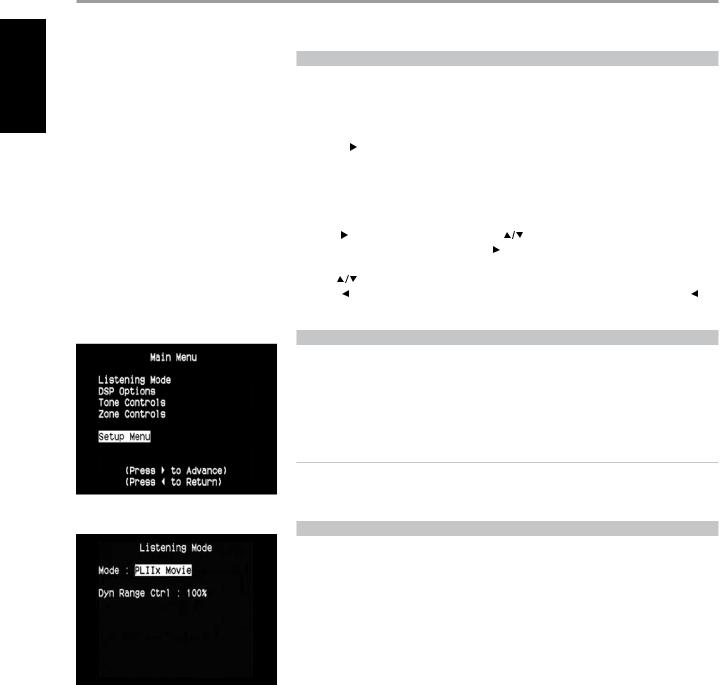
MAIN MENU
The Main Menu contains the menu options for “Listening Mode”, “DSP Options”, “Tone Controls”, “Zone
Controls” and access to “Setup Menu”.
To navigate through these Main Menu options and their sub-menu selections, please refer to and follow the directions stated in the sections “DISPLAY THE OSD” and “NAVIGATING THE OSD AND MAKING CHANGES”.
NOTE
The individual configurations set forth at “Listening Mode”, “DSP Options” and “Tone Controls” are carried over whenever they are enabled during A/V Preset setting. Please see the section “A/V PRESETS” for reference.
LISTENING MODE
The T 755 offers distinct listening modes, tailored for different types of recording or program material.
With a two-channel (Stereo) source, the following listening modes can be selected:
STEREO
All output is directed to the front left/right channels. Low frequencies are directed to the subwoofer if one is present in the Speaker settings. Select “Stereo” when you wish to listen to a stereo (or monaural) production, such as music CD or FM broadcast, without surround enhancement. Stereo recordings whether in PCM/digital or analog form and whether surround-encoded or not encoded,
are reproduced as recorded. Multi-channel digital recordings (Dolby Digital and DTS) are reproduced in “Stereo Downmix” mode via the front left/right channels only as Lt/Rt (left/right-total) signals.
PRO LOGIC
Two-channel recordings, whether stereo or surround-encoded, are reproduced with Dolby Pro Logic surround processing, yielding output to front left/right, center and discrete left/right surround
channels (assuming these are present in the current “Speaker Configuration”). The surround channel is monophonic, but it is reproduced in both surround speakers.
12

OPERATION
USING THE T 755 – MAIN MENU
PRO LOGIC PLII
Dolby Pro Logic II is a more recent evolution of the original Dolby Pro Logic surround processing that yields more stable imaging and full bandwidth sound to the rear channels in Movie mode, offering sound that is more similar to Dolby Digital decoding.
PRO LOGIC IIx
Dolby Pro Logic IIx processes both stereo and 5.1 signals into a 6.1 or 7.1 channel output. At Dolby Pro Logic IIx, you can choose PLIIx Movie or PLIIx Music modes to tailor your listening experience to the source material. Dolby Pro Logic IIx surround processing yields more stable imaging and full bandwidth sound to the rear channels in Movie mode offering sound that is more similar to
Dolby Digital decoding. For two channel signals, Dolby Pro Logic IIx Music mode also features three additional user controls - Dimension, Center Width, and Panorama. See also section about “ADJUSTING LISTENING MODES” below.
The following chart shows the channels available assuming they are enabled in the “Speaker Configuration” menu;
Listening Mode |
Active Decoded Output Channels |
|
|
Two-Channel Sources |
6.1 Speaker System |
7.1 Speaker System |
|
|
|||
|
|
|
|
Dolby Pro Logic IIx Music |
Front (left & right), Center, Surround |
Front (left & right), Center, Surround |
|
(left & right), Back Surround, |
(left & right) and Back Surround (left |
||
Dolby Pro Logic IIx Movie |
|||
Subwoofer |
and right) and subwoofer |
||
|
NOTE
The mention of “Back Surround (left, right)” refers to your external amplifier’s corresponding “Back Right” and “Back Left” speakers (if any) as interfaced with the T 755. The Audio PREOUT makes it possible to use the T 755 as a pre-amplifier to external power amplifiers for some or all channels.
NEO:6
Two-channel recordings, whether stereo or surround-encoded, are reproduced with Neo:6 surround with output to front left/right, center and discrete left/right surround channels plus subwoofer (assuming these are present in the current “Speaker Configuration”). The T 755 provides two DTS Neo:6 variations - CINEMA and MUSIC. See also section about “ADJUSTING LISTENING MODES” below.
EARS
Two-channel recordings, whether stereo or surround-encoded, are reproduced with proprietary NAD surround processing with signals output to the front left/right, center and discrete left/right surround channels, plus subwoofer (assuming these are present in the current “Speaker Configuration”). EARS does not employ the surround back speakers (if any).
EARS extracts the natural ambience present in nearly all well-produced stereo recordings. It does not synthesize any ambience or other sonic elements and thus remains truer to the sound of the original musical performance than most other music-surround options.
Select EARS for listening to stereo music recordings and broadcasts. EARS produces a subtle but highly natural and believable ambience from nearly all “natural-acoustic” stereo recordings. Typically, these include classical, jazz, and folk genres as well as numerous examples from others. Its virtues include realistic, stable “front-stage” sonic imaging and spacious but unexaggerated ambient “virtual acoustics” that remain faithful to the original recording.
ENHANCED STEREO
All recordings reproduced in stereo via the maximum speaker complement configured in the current “Speaker Configuration”. Enhanced stereo can be useful for maximum volume from all channels or for multi-speaker background music (cocktail party) listening. For this mode, Front, Center, Surround and Back speakers can be turned ON/OFF as desired.
ANALOG BYPASS
All analog signals remain in the analog domain without analog-to-digital conversions. At Analog Bypass, the DSP circuitry is bypassed but full tone control functions remain. “Bass management” or “Speaker Setup” settingare also not in effect as these are DSP functions.
ENGLISH
FRANÇAIS
ESPAÑOL
ITALIANO
SVENSKA NEDERLANDS DEUTSCH
РУССКИЙ
13
 Loading...