


 ® C 425
Stereo AM/FM Tuner
Owner’s Manual
Manuel d’Installation
Bedienungsanleitung
Gebruikershandleiding
Manual del Usuario
Manuale delle Istruzioni
Manual do Proprietário
Bruksanvisning
SVENSKA PORTUGUÊS ITALIANO ESPAÑOL NEDERLANDS DEUTSCH FRANÇAIS ENGLISH
SVENSKA PORTUGUÊS ITALIANO ESPAÑOL NEDERLANDS DEUTSCH FRANÇAIS ENGLISH
Introduction
IMPORTANT SAFETY INSTRUCTIONS
EXPLANATION OF GRAPHICAL SYMBOLS
The lightning flash with arrowhead symbol, within an equilateral triangle, is intended to alert the user to the presence of uninsulated “dangerous voltage” within the product’s enclosure that may be of sufficient magnitude to constitute a risk of electric shock to persons.
The exclamation point within an equilateral triangle is intended to alert the user to the presence of important operating and maintenance (servicing) instructions in the literature accompanying the appliance.
PRECAUTIONS
Read the Operating Instructions carefully and completely before operating the unit. Be sure to keep the Operating Instructions for future reference. All warnings and cautions in the Operating Instructions and on the unit should be strictly followed, as well as the safety suggestions below.
1Read these instructions.
2Keep these instructions.
3Head all warnings.
4Follow all instructions.
5Do not use this apparatus near water or moisture.
6Clean only with a dry cloth.
7Do not block any ventilation openings. Install in accordance with the manufacturer’s instructions.
8Do not install near any heat sources, such as radiators, heat registers, stoves or other apparatus (including amplifiers) that produce heat.
9Do not defeat the safety purpose of the polarized or groundingtype plug. A polarized plug has two blades with one wider than the other. A grounding-type plug as two blades and a third grounding prong. The wider blade or third prong are provided for your safety. If the provided plug does not fit in your outlet, consult an electrician for replacement of the obsolete outlet.
10Protect the power cord from being walked on or pinched, particularly at the plugs, convenience receptacles, and the point where they exit from the apparatus.
11Only use attachments/accessories specified by the manufacturer.
12Us only with cart, stand. tripod, bracket or table
specified by the manufacturer or sold with the apparatus. When a cart is used, use caution when moving the cart/apparatus combination to avoid injury from tip-over.
13Unplug this apparatus during lightning storms or when unused for long periods of time.
14Refer all servicing to qualified service personnel. Servicing is required when the apparatus has been damaged in any way: such as power-supply cord or plug damage; liquid has been spilled or objects have fallen into the apparatus; the apparatus has been exposed to rain or moisture, does not operate normally, or has been dropped.
15The mains plug is used as the disconnect device, the disconnect device shall remain readily operable.
WARNING! TO REDUCE THE RISK OF FIRE OR ELECTRONIC SHOCK, DO NOT EXPOSE THIS APPLIANCE TO RAIN OR MOISTURE
This product is manufactured to comply with the radio interference requirements of EEC DIRECTIVE 89/68/EEC and 73/23/EEC
ELECTRIC POWER
1Power Sources - Connect this unit only to power sources specified in the Operating Instructions, and as marked on the unit.
2Polarization - As a safety feature, some units are equipped with polarized AC power plugs which can only be inserted one way into a power outlet. If it is difficult or impossible to insert the AC power plug into an outlet, turn the plug over and try again. If it still does not easily insert into the outlet, please call a qualified service technician to service or replace the outlet. To avoid defeating the safety feature of the polarized plug, do not force it into a power outlet.
3AC power cord - When disconnecting the AC power cord, pull it out by the AC power plug. Do not pull the cord itself.
•Never handle the AC power plug with wet hands, as this could result in fire or shock.
•Power cords should be routed to avoid being severely bent, pinched, or walked upon. Pay particular attention to the cord from the unit to the power socket.
•Avoid overloading AC outlets and extension cords beyond their capacity, as this could result in fire or shock.
4Extension cord - To help prevent electric shock, do not use a polarized AC power plug with an extension cord, receptacle, or other outlet unless the polarized plug can be completely inserted to prevent exposure of the blades of the plug.
5When not in use - Unplug the AC power cord from the AC outlet if the unit will not be used for several months or more. When the cord is plugged in, a small amount of current continues to flow to the unit, even when the power is turned off.
CAUTION
Modifications or adjustments to this product, which are not expressly approved by the manufacturer, may void the user’s right or authority to operate this product.
MAINTENANCE
Clean the unit only as recommended in the Operating Instructions.
DAMAGE REQUIRING SERVICE
Have the unit serviced by a qualified service technician if:
•The AC power plug has been damaged.
•Foreign objects or liquid have gotten inside the unit.
•The unit has been exposed to rain or water - The unit does not seem to operate normally.
•The unit exhibits a marked change in performance.
•The unit has been dropped, or the cabinet has been damaged
DO NOT ATTEMPT TO SERVICE THE UNIT YOURSELF
VENTILATION
The unit should be situated with adequate space around it so that proper ventilation is assured. allow 10 cm (4 in.) clearance from the rear and the top of the unit, and 5 cm (2 in.) from each side. - Do not place on a bed, rug, or similar surface that may block the ventilation openings. - Do not install the unit in a bookcase cabinet, or airtight rack where ventilation may be impeded.
2
ANTENNA INFORMATION
If an indoor antenna is used (either built into the set or installed separately), never allow any part of the antenna to touch the metal parts of other electrical appliances such as a lamp, TV set etc.
CAUTION POWER LINES
Any outdoor antenna must be located away from all power lines.
OUTDOOR ANTENNA GROUNDING
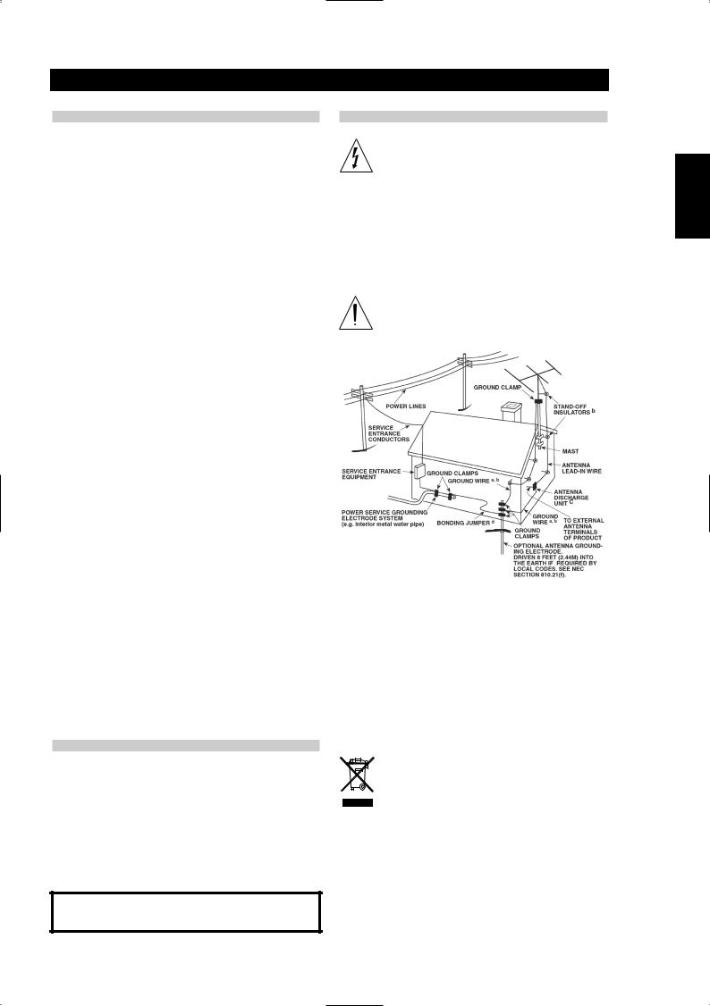
If an outside antenna is connected to your tuner or tuner preamplifier, be sure the antenna system is grounded so as to provide some protection against voltage surges and built-up static charges. Article 810 of the National Electrical Code, ANSI/NFPA No. 70-1984, provides information with respect to proper grounding of the mast and supporting structure, grounding of the lead-in wire to an antenna discharge unit, size of grounding conductors, location of antenna discharge unit, connection to grounding electrodes and requirements for the grounding electrode.
a.Use No. 10 AWG (5.3mm2) copper, No. 8 AWG (8.4mm2) aluminium, No. 17 AWG (1.0mm2) copper-clad steel or bronze wire, or larger, as a ground wire.
b.Secure antenna lead-in and ground wires to house with stand-off insulators spaced from 4-6 feet (1.22 - 1.83 m) apart.
c.Mount antenna discharge unit as close as possible to where the leadin enters house.
d.Use jumper wire not smaller than No.6 AWG (13.3mm2) copper, or the equivalent, when a separate antenna-grounding electrode is used. see NEC Section 810-21 (j).
EXAMPLE OF ANTENNA GROUNDING AS PER NATIONAL ELECTRICAL CODE INSTRUCTIONS CONTAINED IN ARTICLE 810 - RADIO AND TELEVISION EQUIPMENT.
NOTE TO CATV SYSTEM INSTALLER: This reminder is provided to call the CATV system installer’s attention to Article 820-40 of the National Electrical Code that provides guidelines for proper grounding and, in particular, specifies that the ground cable ground shall be connected to the grounding system of the building, as close to the point of cable entry as practical.
OWNER’S RECORD
For your convenience, record the model number and serial number (you will find them on the rear of your set) in the space provided below. Please refer to them when you contact your dealer in case of difficulty.
NOTES ON ENVIRONMENTAL PROTECTION
At the end of its useful life, this product must not be disposed of with regular household waste but must be returned to a collection point for the recycling of electrical and electronic equipment. The symbol on the product, user's manual and packaging, point this out.
The materials can be reused in accordance with their markings. Through re-use, recycling of raw materials, or other forms of recycling of old products, you are making an important contribution to the protection of our environment.
Your local administrative office can advise you of the responsible waste disposal point.
Model No. :
Serial No. :
Introduction
IMPORTANT SAFETY INSTRUCTIONS
WARNINGS AND CAUTIONS
WARNING: The apparatus shall no be exposed to dripping or splashing, and objects filled with liquids, such as vases, shall not be placed on the apparatus. As with any electronic products, use care not to spill liquids into any part of the system. Liquids can cause a failure and/or a fire hazard.
NOTE:
•Where the mains plug or appliance coupler is used as the disconnect device, such disconnect device shall remain readily operable.
NOTE:
•Provide an earth connection before the main plug is connected to the mains.
CAUTION: This product shall be connected to a mains socket outlet with a protective earthing connection.
SVENSKA PORTUGUÊS ITALIANO ESPAÑOL NEDERLANDS DEUTSCH FRANÇAIS ENGLISH
3

SVENSKA PORTUGUÊS ITALIANO ESPAÑOL NEDERLANDS DEUTSCH FRANÇAIS ENGLISH
Introduction
REAR PANEL CONNECTIONS FIGURE 1
FRONT PANEL CONTROLS FIGURE 2
FIGURE 3
FM ANTENNA
DISP
10
10
|
BLEND |
3 |
12 |
FM ANTENNA
AM Loop Antenna
4

Introduction
NOTES ON INSTALLATION
Your NAD C 425 should be placed on a firm, level surface. Avoid placing the unit in direct sunlight, near sources of heat and damp or in poorly ventilated positions. It comes with RCA leads for connection to your amplifier. Ensure that leads and connectors are not damaged in any way and all connectors are firmly pushed home.
If the unit is not going to be used for some time, disconnect the plug from the AC socket. Should water get into your NAD C 425, shut off the power to the unit and remove the plug from the AC socket. Have the unit inspected by a qualified service technician before attempting to use it again.
DO NOT REMOVE THE COVER; THERE ARE NO USERSERVICEABLE PARTS INSIDE.
Use a dry soft cloth to clean the unit. If necessary, lightly dampen the cloth with soapy water. Do not use solutions containing benzyl or other volatile agents.
QUICK START
Use the RCA-to-RCA lead to connect the NAD C 425 left & right outputs to the Tuner Input of your amplifier.
1Connect C 425’s output to amplifier.
2Connect AM and FM antenna (see figure 3).
3Plug in the AC power cord.
4Press the POWER button (No. 1) to turn on the NAD C 425.
5Press the AM/FM button (No. 6) to select AM or FM reception.
6Press Preset/Tune button so that "PRESET" isn’t lit in display; the tuner is now in Tune mode.
7Rotate the PRESET/TUNE Control  or
or  to select a station.
REAR PANEL CONNECTIONS FIGURE 1
1FM Antenna - A ribbon wire FM antenna is included and should be connected to the FM connector at the rear of the unit using the supplied "balun" adaptor (see figure 3). The ribbon aerial should be mounted on a vertical surface and placed so that it forms a "T". Experiment with placement of the antenna to find the position that gives the best signal strength and lowest background noise. An inadequate FM signal normally results in high levels of hiss, especially in stereo, and interference from external electrical sources. In areas of poor FM reception, the tuner section’s performance can be improved by using an externally mounted FM antenna. A qualified aerial installer will be able to advise and fit a recommended aerial for your reception conditions.
2AM Antenna - An AM loop antenna is supplied with the NAD C425 and is required for AM reception. To connect the AM antenna, first press the keys on the Antenna terminals downwards. Insert the bare antenna wires into the two terminal holes and push the connector keys upwards again to secure the connection (see figure 3). Test various positions for the antenna but always ensure the loop is placed vertically for best reception. Placing the antenna close to large metal items such as metal shelves or radiators may interfere with reception.
3Output - Using twin RCA-to-RCA leads, connect to the left (white) and right (red) audio outputs to the "Tuner" input or other line-level input such as "Aux" input of your amplifier. Do not connect this cable to the amplifier’s "Phono" input.
4IR in - The IR IN connector is used to pass commands from other units fitted with IR OUT connectors. This allows centralized control of a complete system, and also allows some of the basic functions of other NAD components (such as a CD player or cassette-deck) also equipped with IR IN to be controlled with an NAD system remote control. To function with such other units, connect the C 425’s IR IN to the IR OUT on the other unit. IR IN connectors can be daisychained, IN to OUT, so that a whole system can be controlled from the remote control facilities of one unit.
NOTE
The NAD C 425 has a built-in receiver for commands from a remote control and doesn’t need to rely on IR IN to be remotely operated. It is advisable not to connect IR IN if the other units that have their own built-in remote control command receiver and are positioned together, in direct view from the remote control handset. If you are unsure, try operating the products without IR IN first; if the unit responds to the remote control command, it will not be necessary to connect IR IN.
5+12V Trigger in - This input allows the C 425 to be switched remotely to Stand-by and On by ancillary equipment such as an amplifier or preamp, AV processor, etc. which are also equipped with a 12V trigger output. For switching Stand-by/Power On of the C 425 by an external component, connect the12V-trigger input of the C 425 to the remote component’s DC output jack. The plug required is a standard 3.5mm Mini-Jack plug ("mono"): The tip is the live or + connection, the shaft of the input jack is the 12V-trigger – or ground connection.
NOTE
The C 425’s 12V Trigger will work within a range of 6 to 15 V DC level and typically draws less than 10mA of current. Check the specifications of the Trigger output terminal on the remote component to ensure it is compatible with the C 425’s 12V trigger input. NAD components equipped with 12V output triggers are fully compatible with the C 425’s 12V input trigger. Before making any connections to any 12V trigger input or output, make sure all components are disconnected from the AC mains. Failure to observe the above may result in damage to the C 425 or any ancillary components attached to it. If in doubt over the connections, installation and operation of the 12V trigger output consult your NAD dealer.
6AC Line cord - Plug the AC power cord into a live AC wall socket or to an AC convenience outlet at the rear of your amplifier.
7RS-232 - Connect to the RS-232 serial port of a home-automation system or personal computer (see “System Integration,” below).
SVENSKA PORTUGUÊS ITALIANO ESPAÑOL NEDERLANDS DEUTSCH FRANÇAIS ENGLISH
5

SVENSKA PORTUGUÊS ITALIANO ESPAÑOL NEDERLANDS DEUTSCH FRANÇAIS ENGLISH
Introduction
FRONT PANEL CONTROLS FIGURE 2
1Power On/Off (TNR 1 Figure 3) - POWER switches the tuner on or off. Pressing the Power switch turns the Tuner on, the Display Panel and Power Status Indicator (No. 2) will light up. Pressing the Power button again will switch the unit off.
NOTE
The C 425 has a receiver for remote control commands built-in. Most NAD system remote control handsets with an On/Off toggle button or separate On and Off button will be able to switch the tuner from On to Stand-by and vice-versa.
The C 425 uses a memory back-up system to store Preset information. This information is retained for several weeks, even if the unit is switched off completely or unplugged. When switching power On, the C 425 will go back to the station last tuned to before the unit was turned off. This will allow you to make timer recordings using an external timer and recorder.
2Power Status Indicator - The Power Status Indicator will light up green when Power is on. When the tuner is switched to Stand-by mode (through either a remote control or the 12V trigger input) the indicator will light up amber. When the unit is switched off completely, it is off.
3Blend (TNR 1 Figure 3) - Weak or remote stereo radio stations are sometimes received with noise and hiss as the antenna signal is too weak. By switching the tuner to mono will reduce the amount of noise and hiss but at the expense of any stereo information. The NAD Blend feature will allow you to reduce the amount noise and hiss but still retain some level of stereo separation, instead of mono. The Blend button toggles between engaging or disengaging the Blend feature; when engaged, "BLEND" lights up in the display.
NOTE
The "Blend" status can be stored for individual presets. Refer to the separate chapter "Storing, Recalling and Labelling Presets" for more information.
4Memory - The Memory is used to store stations into the Preset Memory bank and to store user defined names for non-RDS Preset stations. When Memory is pressed during normal operation, the Preset number and the red "MEMORY" indicator will flash in the Display Panel. If no other buttons are pressed within 12 seconds, the tuner will revert to its previous state. Refer to the separate chapter "Storing, Recalling and Labelling Presets" for more information.
5FM Mute/Mode (TNR 1 Figure 3) - This button combines two functions; it switches the tuner from Stereo to Mono and disengages the muting circuitry at the same time. The muting circuit will mute the tuner in between radio stations when searching or tuning. This way the tuning noise is avoided. The muting circuit however may suppress very weak radio station signals. If a weak station is in stereo it will have a high level of background hiss. Switching to Mono Mode and disengaging the muting circuit by depressing the FM MUTE/MODE button will allow the station to be heard and will cancel most or all of this background noise.
In normal operation the mute circuit is engaged, the display indicates "FM MUTE". Press the FM Mute/Mode button to disengage the muting circuit and switch from stereo to mono reception. "FM MUTE" in the display will extinguish. Press the FM Mute/Mode switch again to return to Auto Stereo FM operation.
NOTE
The "FM Mute/Mode" status can be stored for individual presets. Refer to the separate chapter "Storing, Recalling and Labelling Presets" for more information.
6AM/FM (TNR 1 Figure 3)- The AM/FM button switches the tuner from the AM band to the FM band and vice-versa. The Display Panel shows the frequency of the tuned station and which band is selected. The FM tuning is in 0.05 MHz increments, AM tuning is in 9 kHz or 10 kHz increments, depending on the version.
7Display (TNR 1 Figure 3)- With stations carrying RDS information, The Display button scrolls between three different display modes, each successive push of the button engages the next one of the three modes:
a)In the default mode, the station’s RDS name is displayed, Program Service (PS; normally the station’s calling letters, BBC R3, for instance).
b)From the default mode, press the button once to view Radio Text (RT). This can be additional information such as the presenter’s or program’s name; what song is playing, etc. This text scrolls continuously over the 8 alphanumeric display segments.
c)Press the button from the display RT mode to display the station frequency. Press again to return to the default mode (a).
When tuned to a non-RDS station - The Display button toggles the display to show either the station frequency or user entered station name. If no user name was entered the display will indicate "NO RDS". The Display button is also used to label non-RDS stations with a name. Refer to the separate chapter "Storing, Recalling and Labelling Presets" for more information.
6

Introduction
8Preset/Tune - The PRESET/TUNE button toggles between two different modes:
a)Preset mode: In this mode you can use the PRESET/TUNE Control (No. 10) or
or  to select a Preset. When Preset Mode is selected "PRESET" will scroll once through the display
and the PRESET indicator lights up in the display.
b)Tune mode: By rotating the PRESET/TUNE Control (No. 10)
 or
or  you can engage automatic or manual tuning
respectively down or up the frequency band. When Tune mode is selected, "TUNE" will scroll through the display once.
9Display Area - The display area gives all vital information on the status of the tuner.
Displayed are:
•Band and frequency of current station, RDS PS (station name), or RDS Radio Text. The latter two only if RDS is available; select using the Display button (No. 7).
•If an FM Stereo broadcast is received.
•If the FM station also broadcasts RDS.
•If "Memory" has been engaged
•Preset number if the current station is stored in the tuner’s memory bank.
•If Blend and FM Mute/Mode are switched On.
•Radio Signal Strength. The bars just below "ANTENNA" indicate the radio station’s signal strength. The more bars are lit, the stronger the station.
NOTE
The infrared sensor, which receives commands from a remote control is located on the left side of the display window. There must be a clear line-of-sight path from the remote control to this window; if that path is obstructed, the remote control may not work.
10 Preset/Tune Control (TNR 1 Figure 3)- The function of this control depends on the tuning mode selected with the PRESET/TUNE button (No. 8). The PRESET/TUNE (No. 8) button toggles between the two operational modes:
a)Preset mode (indicated in the display area): Rotate the PRESET/TUNE Control to the left to scroll to a lower number Preset; rotate the PRESET/TUNE Control to the right to scroll to a higher Preset number. This is a "wrap-around" function, so that going from the highest number Preset, the tuner will go to the lowest Preset number or vice-versa either up or down when tuning.
b)Tune mode: Rotate the PRESET/TUNE Control in either direction for more than 1 second to engage automatic tuning respectively up or down the frequency band. The tuner will search automatically for the first reasonably strong radio station, where it will stop. Rotate the PRESET/TUNE Control again for 1 second to start searching again.
By briefly rotating the PRESET/TUNE Control in either direction you will engage manual tuning respectively up or down the frequency band for precise tuning to a specific frequency. With each brief rotation, the tuner will take 0.05 MHz steps on FM so you can accurately tune into the desired frequency. For AM the tuning steps are set at 10 kHz (120V version) or 9 kHz (230V version).
This tuning mode can also be useful when trying to receive a radio station, which is too weak for the auto search mode. When tuned accurately to a station, "TUNED" will light up in the display. The muting circuit however may suppress very weak radio station signals. If such a very weak station is in stereo it will have a high level of background hiss. Switching to Mono Mode and disengaging the muting circuit by depressing the FM MUTE/MODE button (No. 5) will allow the station to be heard and will cancel most or all of this background noise.
NOTES
Automatic tuning is available on both FM and AM.
The PRESET/TUNE  and
and  Controls are used in conjunction with the Memory (No. 4) and Display (No. 7) buttons to add and memorise user defined names to Presets. Refer to the separate chapter "Storing, recalling and labelling Presets" for more information.
11 Sleep Mode (TNR 1 Figure 3) - The Sleep Mode timer will switch the C425 to Standby mode automatically after a preset number of minutes. Pressing the TNR 1's SLEEP button once will display the setting of the sleep time increment. Pressing the TNR 1's SLEEP button a second time within a 3-second period will change the sleep time increment in 30-minute intervals, after which time the C425 will automatically switch into Standby mode. To adjust the sleep delay, press the TNR 1's SLEEP button twice; first to display the sleep time increment, and a second time to change the sleep time increment. Each consecutive press increases the sleep time in 30-minute increments from 30 to 90 minutes. To cancel the sleep mode, continue pressing the TNR 1's SLEEP button until "OFF" displays. Switching the C425 to standby from either the TNR 1's OFF or the C425's Power button will also cancel the sleep mode
12 Dimmer (TNR 1 Figure 3) - The brightness of the C425’s VFD can be adjusted to match your room’s ambient lighting. Press this button once for 1/2 VFD brightness, a second time for completely darkening the VFD, and then a third time to bring the VFD back to full brightness. The brightness will revert to full brightness when power is cycled.
SVENSKA PORTUGUÊS ITALIANO ESPAÑOL NEDERLANDS DEUTSCH FRANÇAIS ENGLISH
7
SVENSKA PORTUGUÊS ITALIANO ESPAÑOL NEDERLANDS DEUTSCH FRANÇAIS ENGLISH
Operation
STORING, RECALLING AND LABELLING PRESETS
Up to 30 presets in total can be stored in the C 425’s memory bank; these can be any mix of either AM or FM stations. When scrolling through the presets, empty preset places will be skipped; it is thus possible to go from preset No. 4 to No. 7 without having seen No. 5 and 6. With the presets you can also store whether you want Blend (No. 3) and FM Mute/Mode (No. 5) to be activated as well every time you recall the preset.
To Store a Preset
•Tune to the radio station you wish to enter into a Preset (refer to this chapter’s section 10). If the station is transmitting RDS information, the RDS indicator will light up and station initials or name will be shown in the Display Panel. If a non-RDS station is found, then just the frequency will be shown.
•Select Blend (No. 3) or FM Mute/Mode (No. 5) if desired.
•To store that station as a Preset, press Memory (No. 4). The Preset number and the red "MEMORY" indicator are flashing in the Display Panel. The lowest available empty preset number will be shown. If no other buttons are pressed within 12 seconds, the tuner will revert to its previous state.
•Press Memory again to store the preset. If you wish to assign a different preset number, rotate the PRESET/TUNE control left or right to select the desired preset number. You can overwrite an existing preset. If the preset number already has been assigned, "MEMORY" will stop blinking, but the preset will continue to blink. When you have selected the desired preset number, press Memory again to store the station.
NOTE
You can enter a new station into an unused Preset or over-write an existing programmed Memory Preset. By doing this you will replace all the data previously held on that Preset number. When Memory is pressed during normal operation, the Preset number and the red "MEMORY" indicator will flash in the Display Panel. If no other buttons are pressed within 12 seconds, the tuner will revert to its previous state. The Memory Presets have a memory back-up, so they will remain stored for several weeks even if the Tuner is switched off or unplugged from the mains supply.
RECALLING A PRESET
•To select a Preset station, the C 425 must be in the Preset mode (the display indicates "PRESET"). If not, press the PRESET/TUNE Mode button (No. 8); "PRESET" will now light up in the display.
•Rotate the Tune/Preset control (No. 10) in either direction until the right Preset is found and shown in the Display Panel. Any unused Presets will be skipped; this avoids having to scroll through empty presets.
DELETING A STORED PRESET
You can empty a Preset by deleting the stored information:
•Select the Preset to be emptied.
•Press and hold the Memory button (No. 4) and Display button (No.7) for two seconds. The preset number and the text "DELETE" will flash in the display.
•Press only the display button again (within default time of 5 seconds) to confirm you want to delete this preset. The text "DELETED" and "—" as the Preset number appear in the display for a couple of seconds.
LABELLING A PRESET
When a station is transmitting RDS information, your NAD C 425 will automatically show the station initials when its Preset is used. Although the Tuner automatically shows the frequency of any other AM or nonRDS Preset station, it also allows you to type in the station name to make it easier to identify which station is stored in the Memory Preset.
To enter a name:
1Select the Preset you want to attach a name to.
2Press and hold the Display button (No. 7) for two seconds. The first space in the Station Data area of the Display Panel will flash.
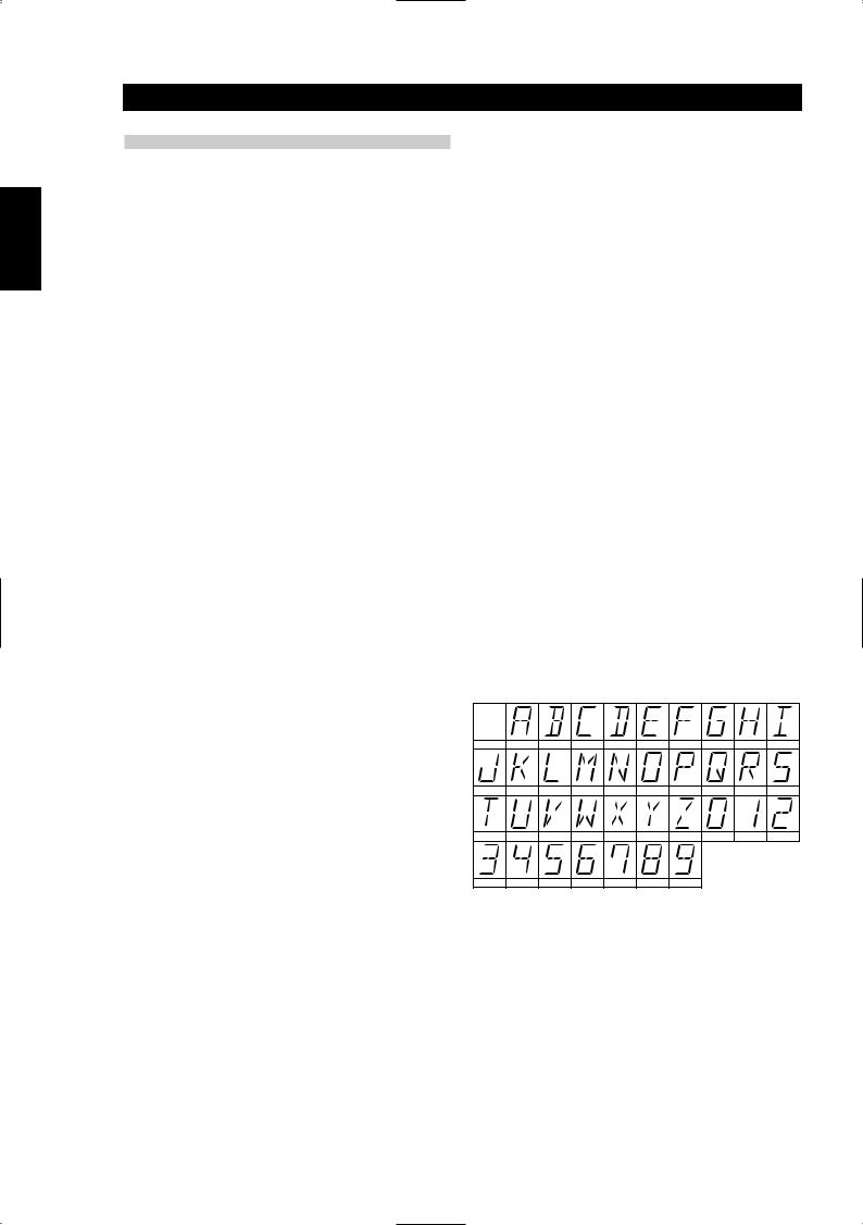
3Rotate the PRESET/TUNE Control (No. 10) in either direction to scroll and select the first character (see Character list below for reference).
4Press Display to move one place to the right to enter the next desired character.
5Rotate the PRESET/TUNE Control again to select the next character in the name and press Memory to store it.
6Repeat steps 3 to 5 until name is complete or all eight places have been filled (up to 8 characters).
7Press Memory once to finish the labelling procedure. Press Memory again to store the completed name.
There are 37 characters available including a blank space.
SPACE |
A |
B |
C |
D |
E |
F |
G |
H |
I |
J |
K |
L |
M |
N |
O |
P |
Q |
R |
S |
T |
U |
V |
W |
X |
Y |
Z |
0 |
1 |
2 |
3 |
4 |
5 |
6 |
7 |
8 |
9 |
|
|
|
NOTE
This function is available only for non-RDS stations. RDS Stations will always display their transmitted name and cannot be over-written.
8

Operation
SETUP FOR CUSTOM AND MULTI-ZONE INSTALLATIONS
REMOTE CONTROL CODES
The NAD C 425 has a remote control command receiver built in so it will respond to NAD remote control commands, such as from most NAD system remote controls. This will allow access to basic functions such as preset up/down.
Particularly with Custom Install in mind, the NAD C 425 will respond to other commands not usually found on NAD remote control handsets. The table below indicates most commands the C 425 recognises.
The NAD C 425 uses the NEC format for IR transmission; customer code is 877C, the corresponding hex codes are next to the IR command:
Function |
HexCode |
Preset |
D2 |
Preset |
D1 |
Tune |
D4 |
Tune |
D3 |
Preset 1 |
8A |
Preset 2 |
8E |
Preset 3 |
92 |
Preset 4 |
96 |
Preset 5 |
8B |
Preset 6 |
8F |
Preset 7 |
93 |
Preset 8 |
97 |
Preset 9 |
98 |
Preset 0 |
C7 |
Power On |
F0 |
Standby |
F1 |
FM Mute/Mode |
37 |
Blend |
35 |
Sleep |
F3 |
Dimmer |
F2 |
Display |
26 |
AM |
82 |
FM |
81 |
12V TRIGGER INPUT
NAD components equipped with 12V output triggers are fully compatible with the C 425’s 12V input trigger.
Plug type: |
3.5mm mono mini-jack |
Operating range: |
6 to 15 V DC |
Current drawn: |
<10mA |
Centre pin = |
+ |
Shaft = |
– |
SYSTEM INTEGRATION (RS-232)
The C425’s RS-232 port offers extensive integration to sophisticated media-system and home-automation control, and permits full control of all of the C425's features. Using this port, the C425 can be connected to any other device with an RS-232 port, such as a personal computer or a home automation system. Any command or function that can be issued from the front panel or the TNR 1 remote controller can be performed via the RS-232 port, and information feedback of the C425’s current settings.
TECHNICAL DETAILS
The RS-232 port uses the following standard pin-out arrangement:
DB-9 Pin # |
Function |
2 |
Transmit Data |
3 |
Receive Data |
5 |
Signal Ground |
DB-9 pin-out Assignment
NOTES:
Use a standard DB-9 male to DB-9 female RS-232 serial cable between your Windows®PC and the C425.
Do not use a null-modem type of RS-232 cable.
Some Windows® PC's may not have RS-232 serial connector. In this event, use a standard "off-the-shelf" RS-232 to USB adaptor to connect to your Windows® PC. Follow the instructions that come with the RS-232 to USB adaptor for setting up the adaptor. Your custom installer or dealer can assist you in the proper setup and configuration of the RS-232 interface.
Neither a DB-9 RS-232 serial cable nor a RS-232 to USB adaptor is supplied with the C425.
Please log onto www.nadelectronics.com for the latest C425 interface control software.
SVENSKA PORTUGUÊS ITALIANO ESPAÑOL NEDERLANDS DEUTSCH FRANÇAIS ENGLISH
9

SVENSKA PORTUGUÊS ITALIANO ESPAÑOL NEDERLANDS DEUTSCH FRANÇAIS ENGLISH
Reference
|
|
|
|
|
|
|
|
|
|
|
|
|
|
|
TROUBLESHOOTING |
|
|
|
|
|
|
PROBLEM |
|
CAUSE |
|
SOLUTION |
|
|
|
|
|
|
|
|
NO SOUND |
• |
Power AC lead unplugged or power not |
• |
Check AC lead |
||
|
|
|
switched on |
|
|
|
|
|
• Signal leads incorrectly connected |
• Check connections to amplifier |
|||
|
|
• Station not selected or weak signal with FM |
• Re-tune or switch off FM Mute |
|||
|
|
|
Mute on |
|
|
|
|
|
• |
Internal fuse blown |
• |
Consult dealer |
|
|
|
|
|
|
|
|
NO SOUND IN ONE CHANNEL |
• |
Signal leads to amplifier disconnected or |
• Check leads and connections |
|||
|
|
|
damaged |
|
|
|
|
|
|
|
|
|
|
NOISE, HISS |
• |
Weak signal |
• Check station tuning. Adjust or replace antenna |
|||
|
|
|
|
|
|
|
DISTORTION |
• |
Multi-path signals or interference from another |
• Check station tuning. Adjust or replace antenna |
|||
|
|
|
station |
|
|
|
|
|
|
|
|
|
|
WHISTLES OR BUZZES ON FM & AM |
• |
Interference from other electrical sources:- |
• Check station tuning. Switch off or move the |
|||
|
|
|
computers, games consoles |
|
source of the electrical noise |
|
|
|
|
|
|
|
|
WHISTLES OR BUZZES ON AM |
• |
Interference from fluorescent lighting or |
• Check station tuning. Adjust or replace AM |
|||
|
|
|
electrical motors |
|
antenna |
|
|
|
|
|
|
|
|
NO RDS INFORMATION |
• |
Station signal too weak |
• Check station tuning Adjust or replace antenna |
|||
|
|
• Station not transmitting RDS data |
• |
No remedy |
||
|
|
|
|
|
|
|
10
Reference
SPECIFICATIONS
AM TUNER SECTION
Usable Sensitivity (999/1000kHz) |
30dBµ |
S/N Ratio (5mV in) |
38dB |
THD (5mV in) |
<3% |
|
|
IF Rejection (450kHz) |
>36dB |
Image Rejection (F+2xIF) |
28dB |
|
|
Selectivity |
17dB |
Output |
130 mV ±20mV |
|
|
Loop Sensitivity (20dB S/N) |
|
999/1000 kHz |
66 dB |
|
|
603/600 kHz |
66 dB |
1404/1400 kHz |
66 dB |
|
|
Frequency response (100 - 2.3 kHz, 5mV) |
±6 dB |
|
|
FM TUNER SECTION European Version / North American Version |
|
Usable Sensitivity (98 MHz) |
6 dBµ / 6 dBµ |
|
|
Signal / Noise Ratio Mono |
>72 dB / 72 dB |
(60 dBµ, IHF wtd) Stereo |
>66 dB / 66 dB |
|
|
Frequency Response (20 Hz - 15 kHz, 60 dBµ) |
±1.0 dB / ±1.0 dB |
Channel Separation (60 dBµ) |
|
|
|
30 Hz |
>33 dB / 33 dB |
1 kHz |
>42 dB / 42 dB |
|
|
10 kHz |
>35 dB / 35 dB |
Alternate Channel Sensitivity (40 dBµ, ±400 kHz) |
60 dB / 45 dB |
|
|
Capture Ratio (40 dBµ) |
1.5 dB / 1.5 dB |
AM Suppression (60 dBµ, 100% Mod.FM, 30% Mod.AM) |
65 dB / 65 dB |
|
|
Image Rejection (119.4 MHz) |
85 dB / 85 dB |
I.F. Rejection (10.7 MHz) |
80 dB / 100 dB |
|
|
Pilot Suppression (60 dBµ) |
60 dB / 60 dB |
THD (60 dBµ, L=R 75 kHz for AH, 40 kHz Dev for C) |
|
|
|
Mono |
0.20% / 0.20% |
Stereo |
0.25% / 0.25% |
|
|
Auto-Search |
|
Sensitivity On |
24 dBµ / 24 dBµ |
|
|
Sensitivity Off |
15 dBµ / 15 dBµ |
RDS Decode Sensitivity |
25 dBµ, 25 dBµ |
|
|
|
|
|
|
PHYSICAL SPECIFICATIONS |
|
Dimensions (Width x Height x Depth) |
435 x 80 x 285 mm (17.12 x 3.15 x 11.22 inches) |
|
|
Net weight |
3.7 kg (8.2 lbs) |
Shipping weight |
5.1 kg (11.22 lbs) |
NAD reserves the right to change specifications without notice.
SVENSKA PORTUGUÊS ITALIANO ESPAÑOL NEDERLANDS DEUTSCH FRANÇAIS ENGLISH
11

ITALIANO ESPAÑOL NEDERLANDS DEUTSCH FRANÇAIS ENGLISH
Português
SVENSKA
NOTES CONCERNANT L’INSTALLATION
Posez le NAD C 425 sur une surface stable, plane et horizontale. Evitez les rayons directs du soleil et les sources de chaleur et d’humidité, ainsi que les endroits où une ventilation correcte ne peut pas être assurée. L’appareil est livré avec des câbles RCA pour effectuer les connexions à votre amplificateur. Vérifiez que les câbles et les connecteurs ne présentent aucune détérioration, et que tous les connecteurs sont bien enfoncés jusqu’en butée.
Si l’appareil doit rester inutilisé pendant un certain temps, débranchez le cordon d’alimentation de la prise de secteur murale. Si de l’eau pénètre à l’intérieur de votre NAD C 425, coupez l’alimentation de l’appareil et retirez la fiche de la prise secteur. Faites contrôler l’appareil par un technicien de service après-vente qualifié, avant toute tentative de remise en service.
NE RETIREZ PAS LE COUVERCLE. A L’INTÉRIEUR, IL N’Y A AUCUN ÉLÉMENT SUR LEQUEL VOUS POURRIEZ INTERVENIR.
Utilisez un chiffon doux sec et propre pour nettoyer l’appareil. Si nécessaire, humectez le chiffon avec un peu d’eau savonneuse. N’utilisez aucune solution contenant du benzol ou un agent volatile quelconque.
MISE EN MARCHE RAPIDE
Utilisez le câble RCA-RCA pour relier les sorties gauche et droite de votre NAD C 425 à l’entrée Tuner de votre amplificateur.
1Branchez la sortie du C 425 à l’amplificateur.
2Branchez les antennes AM et FM(Cf. Figure 3).
3Branchez le cordon d’alimentation secteur.
4Appuyez sur le bouton-poussoir MARCHE-ARRET [POWER] (N° 1) pour mettre le NAD C 425 sous tension.
5Appuyez sur le bouton AM/FM (N° 6) pour sélectionner la réception AM ou FM.
6Appuyez sur le bouton de Préréglage / Accordage [PRESET/TUNE] de manière à éteindre le mot Préréglage [PRESET] sur l’affichage ; le tuner est alors en mode Tune.
7Utilisez les boutons fléchés de préréglage / accordage [PRESET/TUNE
 ou
ou  ] pour trouver une station.
BRANCHEMENTS SUR LE PANNEAU ARRIERE (CF. FIGURE 1)
1ENTREE ANTENNE FM - Une antenne filiaire FM, sous forme de câble plat, est livrée avec le C 425. Cette antenne se branche à l’arrière de l’appareil à l’aide de l’adaptateur "balun" fourni (Cf. Figure 3). L’antenne câble plat doit être fixée sur une surface verticale, et doit former un "T".Faites des essais en mettant l’antenne dans différentes positions, de manière à obtenir le meilleur signal possible avec un minimum de bruit de fond. Un signal FM insuffisant entraîne beaucoup de sifflements, surtout en réception stéréophonique, ainsi que de l’interférence en provenance de sources électriques externes. Dans les endroits où la réception FM est faible, il est possible d’améliorer les performances du tuner en utilisant une antenne FM montée à l’extérieur du bâtiment. Un installateur d’antennes qualifié pourra vous donner les conseils appropriés, et poser une antenne adaptée aux conditions de réception locales.
2ENTREE ANTENNE AM - Une antenne cadre AM est livrée avec le NAD C 425 et permet de recevoir les stations émettant sur la bande AM. Pour brancher l’antenne AM, il faut d’abord pousser les clés sur les bornes d’antenne vers le bas. Insérez les fils d’antenne nus dans les trous des deux bornes puis poussez les clés des bornes vers le haut pour assurer la connexion (Cf. Figure 3). Faites des essais en mettant l’antenne dans différentes positions, mais en vous assurant que le cadre reste toujours vertical afin que la réception soit optimale. Le fait de positionner l’antenne à proximité d’éléments métalliques de taille importante, comme des étagères en métal ou des radiateurs par exemple, peut affecter la réception.
3SORTIE - A l’aide des câbles jumelés RCA vers RCA, brancher les sorties audio gauche (blanc) et droite (rouge) à l’entrée "Tuner" ou d’une autre entrée de niveau ligne, comme par exemple l’entrée "Aux" de votre amplificateur. Ne branchez pas ce câble sur l’entrée "Phono" de l’amplificateur.
4IR IN - Le connecteur d'ENTRÉE [IN] IR est utilisé pour relayer les commandes en provenance d'autres appareils équipés de connecteurs de SORTIE [OUT] IR. Cela permet d'avoir une commande centralisée de la chaîne dans son ensemble, et aussi d'accéder à certaines fonctions de base d'autres équipements NAD (comme par exemple un lecteur CD ou une platine à cassettes), équipés eux aussi de connecteurs de SORTIE [OUT] IR afin de pouvoir être commandés à l'aide d'une télécommande de chaîne NAD. Pour fonctionner de cette manière avec ces autres appareils, reliez le connecteur d'ENTRÉE [IN] IR du C 425 au connecteur de SORTIE [OUT] IR de l'autre appareil. Il est possible de relier les connecteurs d'ENTRÉE [IN] IR aux connecteurs de SORTIE [OUT] IR en boucle continue, de manière à pouvoir commander la chaîne entière à partir du système de télécommande d'un seul appareil.
NOTES
Le NAD C 425 comporte un récepteur intégré pour commandes transmises par une télécommande et n'a pas besoin de son ENTRÉE IR pour pouvoir être télécommandé. Il est conseillé de ne pas connecter l'ENTRÉE IR si les autres appareils possédant leur propre récepteur de télécommande et sont positionnés ensemble, dans la ligne de mire directe du combiné de télécommande. En cas de doute, commencez par essayer de faire fonctionner les produits sans l'ENTRÉE IR ; si l'appareil réagit à la commande émise par la télécommande, ce ne sera pas nécessaire de connecter l'ENTRÉE IR.
5ENTREE ASSERVISSEMENT 12 V [12 V TRIGGER IN] - Cette entrée permet d’assurer la commutation à distance du C 425 entre les modes Veille et Marche, à partir d’un appareil auxiliaire comme un amplificateur ou un préamplificateur, un processeur AV, etc ..., à condition que ces appareils soient aussi équipés d’une sortie asservissement 12 V.
Pour permettre la commutation du C 425 entre les modes Veille et Marche, reliez l’entrée 12 V asservissement [12V-trigger] du C 425 à la prise jack de sortie CC de l’autre appareil. Le connecteur requis est une fiche Mini-Jack standard de 3,5 mm ("mono") : L’extrémité de la fiche jack correspond au "+" et la tige correspond à l’asservissement 12 V, c’est à dire au "-" ou à la masse.
12

NOTES
L’Asservissement 12 V du C 425 fonctionne dans une plage de tension de 6 à 15 V CC, et sa consommation de courant est typiquement inférieure à 10 mA. Vérifiez les caractéristiques de la borne de sortie d’Asservissement du module externe pour vous assurer qu’elles sont compatibles avec l’entrée d’Asservissement 12 V du C 425. Tous les appareils NAD équipés d’une sortie Asservissement 12 V sont entièrement compatibles avec l’entrée Asservissement 12 V du C 425.
Avant de réaliser un quelconque branchement à une entrée ou à une sortie d’Asservissement 12 V, vérifiez que tous les appareils sont débranchés du secteur. Tout non respect de la consigne cidessus pourrait provoquer la détérioration du C 425 ou de tout appareil auxiliaire qui lui est connecté. En cas de doute concernant les branchements, l’installation et l’utilisation de la sortie d’Asservissement 12 V, consultez votre revendeur NAD.
6CORDON ALIMENTATION SECTEUR - Branchez ce cordon à une prise murale secteur ou à une prise commutée à l’arrière de votre amplificateur.
7RS-232 - À brancher au port série RS-232 d’un système domotique ou d’un ordinateur PC (reportez-vous au paragraphe “Intégration Système” ci-après).
COMMANDES SUR LA FACE PARLANTE (CF. FIGURE 2)
1.ALIMENTATION MARCHE / ARRET [POWER ON/OFF] (TNR 1 Figure 3) - Le bouton Marche/Arrêt [POWER] met le tuner sous tension et hors tension. Lorsque vous appuyez sur le bouton Marche/Arrêt [Power], le tuner est mis sous tension et l’Affichage et le Témoin d’Alimentation / Veille s’allument. Une nouvelle impulsion sur le bouton Marche/Arrêt [Power] remet l’appareil hors tension.
NOTES
Le C 425 comporte un récepteur intégré pour les commandes provenant d’un combiné de télécommande. La plupart des télécommandes dotées d’un bouton Marche/arrêt ou de deux boutons Marche et Arrêt permettront de commuter le tuner entre Marche [On] et Veille [Stand-by] et inversement.
Le C 425 dispose d’une mémoire auxiliaire pour sauvegarder les informations présélectionnées. L’appareil retient ces informations pendant plusieurs semaines ; même dans le cas où il mis complètement hors tension ou débranché. A la mise sous tension du C 425, celui-ci affiche la dernière station sélectionnée avant sa mise hors tension. Cette possibilité vous permet de réaliser des enregistrements programmés à l’aide d’une minuterie et d’un enregistreur externe.
2TEMOIN D’ETAT D’ALIMENTATION / VEILLE - Le témoin d’Alimentation / Veille s’allume en vert lorsque l’appareil est sous tension. Si vous mettez le tuner en mode Veille [Stand-by] (à l’aide d’une télécommande ou via l’entrée d’asservissement 12 V), le témoin s’allume en orange. Lorsque l’appareil est complètement hors tension, le témoin est éteint..
3FONDU [BLEND] (TNR 1 Figure 3) - Certaines stations radio stéréo faibles ou éloignées sont parfois captées avec du bruit ou des sifflements dus à un signal d’antenne trop faible. Vous pouvez atténuer le bruit et les sifflements en mettant le tuner sur mono, mais cet apport de qualité d’écoute se fait aux dépens de la stéréophonie. La fonction "Fondu" [Blend] de NAD, quant à elle, vous permet d’atténuer le bruit et les sifflements tout en gardant un certain niveau de séparation stéréophonique, plutôt qu’une monophonie totale. Le bouton Fondu [Blend] permute entre le mode Fondu [Blend] et le mode stéréophonique normal ; lorsque celle-ci est activée, l’indicateur de FONDU [BLEND] s’allume sur l’affichage.
NOTA
L’état d’activation de la fonction "Fondu" peut être mis en mémoire en même temps que les différentes stations préréglées. Reportezvous au chapitre spécifique intitulé "Mise en mémoire, rappel et désignation des stations préréglées" pour plus d’informations.
4MEMOIRE [MEMORY] - La Mémoire est utilisée pour stocker des stations dans la banque de Mémoire des Stations Préréglées, ainsi que pour stocker des désignations définies par l’utilisateur pour les stations préréglées non RDS. Lorsque vous appuyez sur le bouton Mémoire [Memory] pendant le fonctionnement normal du tuner, le numéro de la Station Préréglée et le témoin rouge MEMOIRE [MEMORY] clignotent sur l’affichage. Si vous n’appuyez sur aucun autre bouton pendant 12 secondes, le tuner repasse à l’état qui était actif avant d’appuyer sur MEMOIRE. Reportez-vous au chapitre spécifique intitulé "Mise en mémoire, rappel et désignation des stations préréglées" pour plus d’informations.
5SILENCIEUX DE RECHERCHE FM / MODE FM [FM MUTE/MODE] (TNR 1 Figure 3) - Ce bouton combine deux fonctions ; il fait passer le tuner du mode Stéréo au mode Mono et désactive en même temps les circuits du silencieux de recherche, «muet». Le circuit du silencieux de recherche rend le tuner silencieux entre les stations radio lors de la recherche ou de l’accordage. Ceci permet d’éviter le bruit d’accordage. Il arrive cependant que le circuit silencieux élimine les signaux de stations radio très faibles. Si une station faible est en mode stéréo, vous entendrez un sifflement de fond important. Le fait de passer en mode Mono et de désactiver le circuit du silencieux de recherche, en appuyant sur le bouton Silencieux FM / Mode FM [FM MUTE/MODE], vous permet d’entendre la station et d’annuler tout ou la plupart du bruit de fond.\
En fonctionnement normal, le circuit du silencieux de recherche est activé et l’affichage signale «Silencieux FM» [FM MUTE]. Appuyez sur le bouton Silencieux FM / Mode FM [FM Mute/Mode] pour désactiver le circuit du silencieux et pour changer la réception stéréo en réception mono. Le voyant du Silencieux FM [FM MUTE] s’éteint sur l’affichage. Réappuyez sur le bouton Silencieux FM / Mode FM [FM Mute/Mode] pour retourner à l’état Auto-Stéréo-FM.
NOTA
Il est possible de mettre en mémoire l’état Silencieux FM / Mode FM individuellement pour chaque station préréglée. Reportez-vous au chapitre spécifique intitulé "Mise en mémoire, rappel et désignation des stations préréglées" pour plus d’informations.
6AM/FM (TNR 1 Figure 3) - Le bouton AM/FM permute le tuner entre la bande AM et la bande FM et inversement. L’affichage signale la fréquence de la station accordée et la bande sélectionnée. L’accordage FM se fait par pas de 0,05 MHz, tandis que l’accordage AM se fait par pas de 9 ou 10 kHz, en fonction de la version.
SVENSKA PORTUGUÊS ITALIANO ESPAÑOL NEDERLANDS DEUTSCH FRANÇAIS ENGLISH
13

SVENSKA PORTUGUÊS ITALIANO ESPAÑOL NEDERLANDS DEUTSCH FRANÇAIS ENGLISH
7AFFICHAGE (TNR 1 Figure 3) - Pour les stations offrant des informations RDS, le bouton d’Affichage [Display] fait défiler trois différents modes d’affichage et chaque impulsion successive sur le bouton active le mode suivant parmi les trois modes :
a)En mode par défaut [default], l’affichage indique le nom RDS de la station, "Service Programme" [Program Service] (PS ; normalement le sigle d’une station, p.ex. EUROPE 1).
b)En partant de ce mode par défaut, appuyez une fois sur le bouton pour afficher le Radio Texte (RT). Ce mode peut offrir des informations supplémentaires, comme par exemple le nom du présentateur ou du programme, la chanson qui passe, etc. Ce texte défile en continu sur les 8 segments de l’affichage alphanumérique.
c)Appuyez sur le bouton du mode d’affichage RT pour afficher la fréquence de la station. Réappuyez pour retourner au mode par défaut (a).
Accordage sur une station sans RDS - Le bouton d’affichage [Display] bascule l’affichage pour afficher soit la fréquence de la station, soit le nom de station entré par l’utilisateur. Si aucun nom d’utilisateur n’a été entré, l’affichage indique "PAS DE RDS" [NO RDS]. Le bouton d’Affichage [Display] permet aussi d’enregistrer une désignation pour les stations non RDS. Reportez-vous au chapitre spécifique intitulé "Mise en mémoire, rappel et désignation des stations préréglées" pour plus d’informations.
8PRE-REGLAGE / ACCORDAGE [PRESET/TUNE] - Le bouton de Préréglage / Accordage [PRESET/TUNE] permute entre deux modes différents :
a)Mode Station Préréglée [Preset] : Grâce à ce mode, vous
pouvez utiliser les boutons fléchés de Préréglage / Accordage
 ou
ou  (N° 10) pour choisir une station préréglée. Lorsque le mode de Préréglage est sélectionné, le mot PREREGLAGE [PRESET] défile une fois sur l’affichage, puis le témoin de PREREGLAGE [PRESET] s’allume sur l’affichage.
b)Mode Accordage [Tune] : En appuyant sur les boutons fléchés de Préréglage / Accordage  ou
ou  (N° 10), vous pouvez activer l’accordage automatique ou manuel en
parcourant la bande de fréquences vers le haut ou vers le bas, respectivement. Lorsque le mode de d’Accordage est sélectionné, le mot ACCORDAGE [TUNE] défile une fois sur l’affichage.
9ZONE D’AFFICHAGE - La zone d’affichage vous permet de voir toutes les informations essentielles concernant l’état du tuner. Les informations suivantes sont affichées :
• La bande et la fréquence de la station sélectionnée, RDS PS (nom de la station), ou RDS Radio Text. RDS Radio Text n’est affiché que si le RDS est disponible ; La sélection se fait à l’aide du bouton d’Affichage [Display] (No. 7).
• FM Stereo, si l’émission captée est en FM Stéréo
• Si la station FM émet ou non des signaux RDS.
• Si un bouton de Présélection a été utilisé
• Le numéro de la station préréglée, si la station en cours de réception a été mise en mémoire dans la banque de mémoire du tuner.
• Fondu [Blend] et Silencieux FM / Mode FM [FM Mute/Mode] si ces fonctions sont actives.
• La Puissance du Signal Radio. Les barres sous le mot "ANTENNE" [ANTENNA] donnent une indication de la puissance de la station radio. Plus il y de barres allumées, plus la station est puissante.
NOTA
Le capteur infrarouge recevant les commandes émises à partir d’un combiné de télécommande se trouve dans le côté gauche de la fenêtre d’affichage. L’espace entre la télécommande et le récepteur doit être dégagé de tout obstacle, sinon la télécommande pourrait refuser de fonctionner.
10 COMMANDE DE PRÉRÉGLAGE / ACCORDAGE [PRESET / TUNE] (TNR 1 Figure 3) - La fonction de cette commande dépend du mode d'accordage sélectionné à l'aide du bouton de PRÉRÉGLAGE / ACCORDAGE [PRESET / TUNE] (N° 8). Le bouton de PRÉRÉGLAGE / ACCORDAGE permute entre les deux modes de fonctionnement:
a)Mode préréglage (indiqué dans la zone d'affichage):
Tournez la commande de PRÉRÉGLAGE / ACCORDAGE [PRESET
/TUNE] vers la gauche pour faire défiler les numéros des stations préréglées dans le sens décroissant ; tournez la commande de PRÉRÉGLAGE / ACCORDAGE vers la droite pour faire défiler les numéros des stations préréglées dans le sens croissant. Il s'agit d'une fonction "en boucle", c'est à dire qu'après avoir atteint le numéro de station préréglée le plus élevé, le tuner passe directement au numéro le plus bas (ou inversement), soit en montant, soit en descendant pendant l'accordage.
b)Mode accordage: Tournez la commande de PRÉRÉGLAGE / ACCORDAGE [PRESET / TUNE] vers la droite ou vers la gauche, pendant plus d'une seconde, pour démarrer l'accordage automatique en montant ou en descendant sur la bande de fréquences, respectivement. Le tuner recherchera automatiquement la première station suffisamment puissante et s'arrêtera dessus. Tournez à nouveau la commande de PRÉRÉGLAGE / ACCORDAGE pendant une seconde pour relancer la recherche. En tournant la commande de PRÉRÉGLAGE
/ACCORDAGE par de brèves impulsions, vers la droite ou vers la gauche, vous pouvez effectuer un accordage manuel en montant ou en descendant sur la bande de fréquences, respectivement, de manière à afficher une fréquence spécifique. Pour chaque rotation brève, le tuner fera un saut de 0,1 MHz (version 120 V) ou de 0,05 MHz (version 230 V) sur la bande FM, de manière à vous permettre d'accorder la fréquence que vous voulez. Sur la bande AM, les pas d'accordage sont définis à 10 kHz (version 120 V) ou à 9 kHz (version 230 V).
Ce mode d'accordage peut aussi être utile lorsque vous essayez de recevoir une station de radio qui est trop faible pour être détectée par le mode de recherche automatique. Lorsque le tuner est accordé de façon précise sur une station, le mot "ACCORDÉ" ["TUNED"] s'allume sur l'affichage. Il arrive, néanmoins, que le circuit de silencieux de recherche supprime les signaux émis par les stations radio très faibles. Si une telle station émet en stéréo, elle sera assortie d'un sifflement de fond assez fort. Si vous désactivez le circuit de silencieux de recherche en appuyant sur la touche SILENCIEUX DE RECHERCHE FM / MODE FM [FM MUTE/MODE] (N° 5), il vous sera possible d'entendre la station et la plupart du bruit de fond disparaîtra.
14

NOTES
L'accordage automatique est disponible aussi bien en FM qu'en AM. Certaines télécommandes de chaîne NAD, compatibles avec le NAD C 425, comportent des fonctions de recherche des stations préréglées vers le haut et vers le bas. Même si le C 425 est en Mode Accordage, l'un ou l'autre de ces boutons de STATIONS PRÉRÉGLÉES [PRESET] de la télécommande n'aura pour effet que de changer de station préréglée. Vous pouvez aussi utiliser les boutons de PRÉRÉGLAGE / ACCORDAGE [PRESET / TUNE  et
et  ] avec les boutons de MÉMOIRE [MEMORY] (N° 4) et d'AFFICHAGE [DISPLAY] (N° 7), pour ajouter et mettre en mémoire des désignations que vous définirez vous-même pour les stations préréglées. Pour plus d'informations, reportez-vous au chapitre "MISE EN MÉMOIRE, RAPPEL ET DÉSIGNATION DES STATIONS PRÉRÉGLÉES [PRESETS]
11 MODE SOMMEIL [SLEEP] (TNR 1 Figure 3) - La minuterie du Mode Sommeil [Sleep] met automatiquement le C425 en mode Veille [Standby] après un nombre de minutes préréglé. Une impulsion unique sur le bouton SOMMEIL [SLEEP] de la télécommande TNR 1 affiche l'incrément du temps de sommeil actuellement réglé. Une deuxième impulsion sur le bouton SOMMEIL [SLEEP] de la télécommande TNR 1, dans les trois secondes qui suivent, et chaque impulsion successive par la suite, augmentent le temps de sommeil d'un intervalle de 30 minutes ; une fois le temps de sommeil écoulé, le C425 se met automatiquement en mode Veille [Standby].
Pour régler la minuterie de sommeil, appuyez deux fois sur le bouton SOMMEIL [SLEEP] de la télécommande TNR 1; la première impulsion affiche le temps de sommeil actuellement réglé, puis la deuxième incrémente la valeur. Chaque impulsion successive augmente le temps de sommeil de 30 minutes, pour aller de 30 minutes jusqu'à 90 minutes. Pour annuler le mode sommeil, continuez à appuyer sur le bouton SOMMEIL [SLEEP] de la télécommande TNR 1 jusqu'à ce que "ARRÊTÉ" ["OFF"] soit affiché sur le VFD. Si vous commutez le C425 en mode Veille, en appuyant soit sur le bouton ARRÊT [OFF] de la télécommande TNR 1, soit sur le bouton MARCHE/ARRÊT [POWER] du C425, cela annule aussi le mode sommeil.
12 RÉGLAGE DE LA LUMINOSITÉ (TNR 1 Figure 3) - La luminosité de l'Affichage Vide-Fluorescent [VFD] du C425 est réglable en fonction de la lumière ambiante de votre pièce. Appuyez une fois sur ce bouton pour diminuer de moitié l'intensité lumineuse du VFD, puis une deuxième fois pour l'assombrir complètement ; une troisième impulsion fait revenir la luminosité du VFD à sa pleine intensité. L'intensité revient au maximum si vous éteignez, puis rallumez l'appareil.
MISE EN MEMOIRE, RAPPEL ET DESIGNATION
DE STATIONS PREREGLEES [PRESETS]
Il est possible de stocker jusqu’à 30 stations préréglées dans la banque de mémoire du C 425 ; il peut s’agir de n’importe quel panachage de stations AM ou FM. Lorsque vous faites défiler les stations préréglées, les emplacements non utilisés sont sautés. Cela veut dire qu’il est possible de passer de la station préréglée N° 4 à la N° 7, sans pour autant voir passer la N° 5 et la N° 6 si elles ne contiennent aucune station préréglée En mettant en mémoire vos stations préréglées, vous pouvez aussi préciser si vous voulez que les modes Fondu [Blend] (N° 3) et/ou Silencieux FM / Mode FM (N° 5) soient activés chaque fois que vous choisissez telle ou telle station préréglée.
MISE EN MEMOIRE D’UNE STATION PREREGLEE
•Accordez le tuner sur la station radio que vous voulez mettre en mémoire (reportez-vous à la section 10 de ce même chapitre). Si la station émet des informations RDS, le voyant RDS s’allumera et les initiales ou le nom sera indiqué sur l’affichage. Si le tuner trouve une station sans RDS, seule la fréquence sera affichée..
•Sélectionnez les modes Fondu [Blend] (N° 3) et/ou Silencieux FM / Mode FM (N° 5), si vous le souhaitez..
•Pour mettre cette station en mémoire comme une station préréglée, appuyez sur le bouton MEMOIRE [MEMORY] (N° 4). Le numéro de la station préréglée et le témoin rouge MEMOIRE [MEMORY] clignotent sur le panneau d’affichage. Le numéro de station préréglée libre le moins élevé s’affiche. Si vous n’appuyez sur aucun autre bouton dans un délai de 12 secondes, le tuner repassera à son état précédent.
•Appuyez à nouveau sur MÉMOIRE [MEMORY] pour mettre la station en mémoire. Si vous préférez affecter un autre numéro de préréglage à cette station, tournez la commande de PRÉRÉGLAGE / ACCORDAGE [PRESET / TUNE] vers la gauche ou vers la droite pour afficher le numéro de station souhaité. Vous pouvez écraser une station préréglée existante. Si le numéro que vous sélectionnez contient déjà une station, le mot MÉMOIRE [MEMORY] cessera de clignoter mais le numéro de station clignotera encore. Une fois que vous aurez sélectionné le numéro de station que vous voulez, appuyez à nouveau sur le bouton MÉMOIRE [MEMORY] pour mettre la station en mémoire.
NOTES
Vous pouvez entrer une nouvelle station sous un numéro de Station Préréglée libre, ou remplacer une Station Préréglée déjà programmée. Vous détruisez ainsi toutes les données déjà mémorisées sous ce numéro de Station Préréglée.
Lorsque vous appuyez sur le bouton Mémoire [Memory] en fonctionnement normal, le numéro de station préréglée et le témoin rouge MEMOIRE [MEMORY] se mettent à clignoter sur le panneau d’affichage. Si vous n’appuyez sur aucun autre bouton dans un délai de 12 secondes, le tuner repassera à son état précédent. Les valeurs présélectionnées sont aussi sauvegardées en mémoire auxiliaire, afin de les conserver pendant plusieurs semaines même si le tuner est éteint, débranché ou si l’alimentation secteur est coupée.
RAPPEL D'UNE STATION PRÉRÉGLÉE [PRESET]
•Pour pouvoir choisir une station préréglée, le C 425 doit être en mode Préréglage (si c'est le cas, l'affichage indique PRÉRÉGLAGE [PRESET]). Sinon, appuyez sur le bouton de MODE PRÉRÉGLAGE / ACCORDAGE [PRESET / TUNE MODE] (N° 8). Le mot PRÉRÉGLAGE [PRESET] s'allumera sur l'affichage.
•Tournez la commande de PRÉRÉGLAGE / ACCORDAGE [PRESET / TUNE] (N° 10) dans un sens ou dans l'autre, jusqu’à ce que la station préréglée que vous cherchez soit indiquée sur l’affichage.
SVENSKA PORTUGUÊS ITALIANO ESPAÑOL NEDERLANDS DEUTSCH FRANÇAIS ENGLISH
15
SVENSKA PORTUGUÊS ITALIANO ESPAÑOL NEDERLANDS DEUTSCH FRANÇAIS ENGLISH
SUPPRESSION D’UNE STATION DE LA MEMOIRE
Vous pouvez vider un numéro de Station Préréglée en effaçant toutes ses informations mémorisées.
•Sélectionnez le numéro de Station Préréglée à vider.
•Appuyez pendant 2 secondes sur le bouton Mémoire [Memory (N° 4) et sur le bouton d’Affichage [Display] (N° 7). Le numéro de la station préréglée et le texte SUPPRIMER [DELETE] clignote sur le panneau d’affichage.
•Appuyez ensuite sur le bouton d’Affichage [Display] seul (dans un délai de 5 secondes) pour valider la suppression de la station préréglée concernée. Le texte SUPPRIME [DELETED] et "—" en guise de numéro de station préréglée apparaissent sur le panneau d’affichage pendant quelques secondes.
CREATION D’UNE DESIGNATION DE STATION PREREGLEE
Lorsqu’une station émet des informations RDS, votre NAD C 425 indique automatiquement les initiales de la station dans le cas d’une Station Préréglée. Le Tuner montre automatiquement la fréquence de toute station présélectionnée AM ou sans RDS, mais il vous permet également d’entrer le nom de la station afin d’identifier plus facilement quelle station est sauvegardée en mémoire sous un numéro de présélection donné. Pour entrer une désignation :
1Sélectionnez la Station Préréglée que vous souhaitez nommer.
2Appuyez sur le bouton d’Affichage [Display] (N° 7) pendant deux secondes. Le premier emplacement dans la zone Données Station [Station Data] du Panneau d’Affichage clignote.
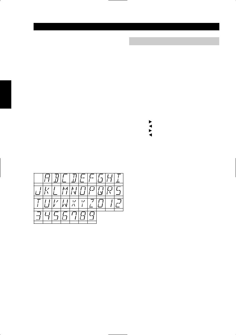
3Tournez la commande de PRÉRÉGLAGE / ACCORDAGE [PRESET / TUNE] (N° 10) dans un sens ou dans l'autre, pour faire défiler et sélectionner le premier caractère (Reportez-vous à la liste des caractères ci-dessous).
SPACE |
A |
B |
C |
D |
E |
F |
G |
H |
I |
J |
K |
L |
M |
N |
O |
P |
Q |
R |
S |
T |
U |
V |
W |
X |
Y |
Z |
0 |
1 |
2 |
3 |
4 |
5 |
6 |
7 |
8 |
9 |
|
|
|
4Appuyez sur le bouton d’Affichage [Display] pour déplacer le curseur vers la droite d’un caractère, afin de pouvoir entrer le caractère suivant de la désignation.
5Tournez à nouveau la commande de PRÉRÉGLAGE / ACCORDAGE pour sélectionner le caractère suivant de la désignation, puis appuyez sur Mémoire [Memory] pour le mettre en mémoire.
6Reprendre les opérations 3 à 5 autant de fois que nécessaire pour compléter la désignation, jusqu’à concurrence de 8 caractères en tout.
7Appuyez une fois sur Mémoire [Memory] pour terminer l’opération de désignation. Appuyez à nouveau sur Memory [Mémoire] pour mémoriser le nom complet. 37 caractères sont disponibles, y compris un caractère d’espace.
NOTA
Cette fonction est uniquement disponible pour les stations sans RDS. Les stations RDS afficheront toujours la désignation transmise par l’émetteur. Cette désignation ne peut pas être écrasée par une autre.
CONFIGURATION POUR INSTALLATIONS PARTICULIÈRES ET
MULTI-ZONES
CODES DE TELECOMMANDE
Le NAD C 425 possède son propre récepteur de télécommandes intégré, ce qui lui permet de réagir à des commandes émises par la plupart des combinés de télécommande NAD. Cela permet d’accéder aux fonctions de base, comme par exemple Préréglage Haut/Bas, Marche/Veille, etc ...
Partant du principe que l’utilisateur risque de vouloir une Installation Particulière sur mesure, le NAD C 425 a été conçu pour réagir à d’autres commandes ne se trouvant généralement pas sur les combinés de télécommande NAD. Le tableau ci-dessous donne la liste de toutes les commandes reconnues par le C 425 .
Le NAD C 425 utilise le format NEC pour la transmission IR ; Le code client est 877C et le code correspondant en hexadécimal est énuméré en face de chaque commande IR :
|
N° Fonction |
Code Hexa |
|
Préréglage |
D2 |
|
Préréglage |
D1 |
|
Accordage |
D4 |
|
Accordage |
D3 |
|
Station préréglée 1 |
8A |
|
Station préréglée 2 |
8E |
|
Station préréglée 3 |
92 |
|
Station préréglée 4 |
94 |
|
Station préréglée 5 |
8B |
|
Station préréglée 6 |
8F |
|
Station préréglée 7 |
93 |
|
Station préréglée 8 |
97 |
|
Station préréglée 9 |
98 |
|
Station préréglée 0 |
C7 |
|
Marche |
F0 |
|
Veille |
F1 |
|
FM Mute/Mode |
37 |
|
Blend |
35 |
|
Sleep |
F3 |
|
Dimmer |
F2 |
0 |
Display |
26 |
1 |
AM |
82 |
2 |
FM |
81 |
16

ENTREE "ASSERVISSEMENT 12 V" [12 V TRIGGER INPUT]
Tous les appareils NAD équipés d’une sortie "Asservissement 12 V" sont entièrement compatibles avec l’entrée "Asservissement 12 V" du C 425.
Type de connecteur: |
mini-jack 3,5 mm mono |
Plage de fonctionnement: |
à 15 V CC |
Courant: |
< 10 mA |
Broche centrale = |
+ |
Axe = |
– |
INTÉGRATION SYSTÈME (RS-232)
Le port RS-232 du C425 offre d’importantes possibilités d’intégration de commande par des systèmes multimédia évolués ou par un système domotique ; toutes les fonctionnalités du C425 peuvent être commandées à partir de ce port. Grâce à ce port, le C425 peut être relié à n’importe quel autre dispositif qui possède, lui aussi, un port RS-232, comme par exemple un ordinateur PC ou un système domotique. Toute commande ou fonction accessible depuis la face parlante ou la télécommande TNR 1 peut être réalisée via le port RS-232, de plus, le retour d’informations concernant la configuration actuelle du C425.
INFORMATIONS TECHNIQUES
Le port RS-232 utilise le brochage standard suivant :
N˚ broche DB-9 |
Fonction |
2 |
Données transmises |
3 |
Données reçues |
5 |
Masse des signaux |
Brochage du connecteur DB-9
NOTES:
Utiliser un câble série RS-232 DB-9 mâle à DB-9 femelle entre le PC sous Windows® et le C425.
Ne pas utiliser de câble RS-232 de type null-modem. Certains ordinateurs sous Windows® peuvent ne pas avoir de connecteur série RS-232. Dans ce cas, utiliser un adaptateur courant RS-232 à USB pour relier l’ordinateur sous Windows® au C425. Suivre les instructions fournies avec l’adaptateur RS-232 à USB pour installer ce dernier. L’installateur ou le revendeur peut déterminer le montage et la configuration corrects de l’interface RS-232.
Aucun câble série DB-9 RS-232, ni adaptateur RS-232 à USB n’est fourni avec le C425.
Consulter le site web www.nadelectronics.com pour obtenir la dernière version du logiciel de commande d’interface du C425.
SVENSKA PORTUGUÊS ITALIANO ESPAÑOL NEDERLANDS DEUTSCH FRANÇAIS ENGLISH
17

SVENSKA PORTUGUÊS ITALIANO ESPAÑOL NEDERLANDS DEUTSCH FRANÇAIS ENGLISH
|
|
|
|
|
|
|
|
|
|
|
|
|
|
|
DEPANNAGE |
|
|
|
|
|
|
Problème |
|
Cause |
|
Solution |
|
|
|
|
|
|
|
|
AUCUN SON |
• |
Câble secteur débranché, ou alimentation |
• Vérifiez le câble secteur |
|||
|
|
|
coupée |
|
|
|
|
|
• Les câbles de transmission des signaux ne sont |
• Vérifiez les connexions de l’amplificateur |
|||
|
|
|
pas branchés de façon correcte |
|
|
|
|
|
• La station n’est pas sélectionnée ou le signal est |
• Accordez la station à nouveau, ou désactivez le |
|||
|
|
|
faible alors que le Silencieux FM [FM Mute] est |
|
Silencieux FM [FM Mute] |
|
|
|
|
actif |
|
|
|
|
|
• |
Fusible interne grillé |
• |
Consultez le revendeur |
|
|
|
|
|
|
|
|
AUCUN SON SUR UNE VOIE |
• |
Les câbles de transmission des signaux vers |
• Vérifiez les câbles et les branchements. |
|||
|
|
|
l’amplificateur sont débranchés ou abîmés |
|
|
|
|
|
|
|
|
|
|
BRUIT, SIFFLEMENTS |
• |
Signal faible |
• Vérifiez le réglage de la station. Réglez ou |
|||
|
|
|
|
|
remplacez l’antenne |
|
|
|
|
|
|
|
|
DISTORSION |
• |
Signaux multivoies ou interférence d’une autre |
• Vérifiez le réglage de la station. Réglez ou |
|||
|
|
|
station |
|
remplacez l’antenne |
|
|
|
|
|
|
|
|
SIFFLEMENTS OU BOURDONNEMENTS |
• |
Interférences en provenance d’autres sources |
• Vérifiez le réglage de la station. Eteignez ou |
|||
SUR LA BANDE FM ET SUR LA BANDE AM |
|
électriques - ordinateurs, consoles de jeux |
|
déplacez la source du bruit électrique |
||
|
|
|
|
|
|
|
SIFFLEMENTS OU BOURDONNEMENTS |
• |
Interférences en provenance d’éclairages ou de |
• Vérifiez le réglage de la station. Réglez ou |
|||
SUR LA BANDE AM |
|
moteurs électriques |
|
remplacez l’antenne AM |
||
|
|
|
|
|
|
|
SANS INFORMATIONS RDS |
• |
Le signal de la station est trop faible |
• Vérifiez le réglage de la station. Réglez ou |
|||
|
|
|
|
|
remplacez l’antenne. |
|
|
|
• La station n’émet pas d’informations RDS |
• |
Sans remède |
||
|
|
|
|
|
|
|
18

CARACTÉRISTIQUES
SECTION TUNER AM
Sensibilité utile (999/1000 kHz) |
30 dBµ |
Rapport signal/bruit (entrée 5 mV) |
38 dB |
Distorsion Harmonique Totale (entrée 5 mV) |
<3 % |
|
|
Réjection FI (450 kHz) |
>36 dB |
Réjection image (F+2xFI) |
28 dB |
|
|
Sélectivité |
17 dB |
Sortie |
130 mV ± 20 mV |
|
|
Sensibilité du cadre (20 dB S/B) |
|
999/1000 kHz |
66 dB |
|
|
603/600 kHz |
66 dB |
1404/1400 kHz |
66 dB |
|
|
Réponse de fréquence (100 - 2,3 kHz, 5 mV) |
± 6 dB |
|
|
SECTION TUNER FM Version Europe / Version Amérique du Nord |
|
Sensibilité utile (98 MHz) |
6 dBµ / 6 dBµ |
|
|
Rapport signal/bruit mono |
>72 dB / 72 dB |
(60 dBµ, IHF pondéré) Stéréo |
>66 dB / 66 dB |
|
|
Réponse de fréquence (20 Hz - 15 kHz, 60 dBµ) |
± 1,0 dB / ± 1,0 dB |
Séparation des voies (60 dBµ) |
|
|
|
30 Hz |
>33 dB / 33 dB |
1 kHz |
>42 dB / 42 dB |
|
|
10 kHz |
>35 dB / 35 dB |
Sensibilité de voie alternative (40 dBµ, ± 400 kHz) |
60 dB / 45 dB |
|
|
Rapport de Capture (40 dBµ) |
1,5 dB / 1,5 dB |
Filtrage AM (60 dBµ, 100 % Mod. FM, 30 % Mod. AM) |
65 dB / 65 dB |
|
|
Réjection image (119,4 MHz) |
85 dB / 85 dB |
Réjection F.I. (10,7 MHz) |
80 dB / 100 dB |
|
|
Filtrage pilote (60 dBµ) |
60 dB / 60 dB |
Distorsion Harmonique Totale (60 dBµ, G = D 75 kHz pour AH, 40 kHz Dév pour C)
Mono |
0,20 % / 0,20 % |
Stéréo |
0,25 % / 0,25 % |
|
|
Sensibilité de recherche automatique |
|
Active |
24 dBµ / 24 dBµ |
|
|
Non-active |
15 dBµ / 15 dBµ |
Sensibilité de décodage RDS |
25 dBµ / 25 dBµ |
|
|
|
|
CARACTÉRISTIQUES PHYSIQUES |
|
|
|
Dimensions (Largeur x Hauteur x Profondeur) |
435 x 80 x 285 mm |
Poids net |
3,7 kg (8,2 lbs) |
|
|
Poids emballé |
5,1 kg (11,22 lbs) |
NAD se réserve le droit de modifier les spécifications sans préavis. |
|
SVENSKA PORTUGUÊS ITALIANO ESPAÑOL NEDERLANDS DEUTSCH FRANÇAIS ENGLISH
19

SVENSKA PORTUGUÊS ITALIANO ESPAÑOL NEDERLANDS DEUTSCH FRANÇAIS ENGLISH
HINWEISE ZUR AUFSTELLUNG
Der NAD C 425 sollte auf einer festen und ebenen Oberfläche aufgestellt werden. Vermeiden Sie es, das Gerät direktem Sonnenlicht oder Hitze und Feuchtigkeit auszusetzen. Stellen Sie es nicht an schlecht belüfteten Orten auf. Das Gerät wird mit einer gummiisolierten Anschlußleitung für die Verbindung mit dem Verstärker geliefert. Achten Sie darauf, daß Anschlußleitungen und Buchsen frei von Beschädigungen sind und alle Steckverbindungen fest sitzen.
Ziehen Sie den Netzstecker aus der Steckdose, wenn das Gerät längere Zeit nicht benutzt wird. Sollte Wasser in den NAD C 425 eindringen, schalten Sie das Gerät aus und ziehen den Netzstecker aus der Steckdose. Lassen Sie das Gerät von einem qualifizierten Servicetechniker untersuchen, bevor Sie es wieder verwenden.
NEHMEN SIE NICHT DEN GEHÄUSEDECKEL AB. IM GERÄTEINNERN BEFINDEN SICH KEINE VOM BENUTZER REPARIERBAREN TEILE.
Säubern Sie das Gerät mit einem trockenen weichen Tuch. Befeuchten Sie das Tuch bei Bedarf leicht mit etwas Seifenwasser. Verwenden Sie keine Lösungsmittel, die Benzol oder andere Verdunstungsmittel enthalten.
SCHNELLSTART
Schließen Sie den linken und rechten Ausgang des NAD C 425 mit dem gummiisolierten Anschlußkabel am Eingang TUNER des Verstärkers an.
1Verbinden sie den Ausgang des C 425 mit dem Verstärker.
2Schließen Sie die AMund FM-Antenne an (Abb. 3).
3Stecken Sie das Netzkabel ein.
4Drücken Sie die Taste POWER (Nr. 1), um den NAD C 425 einzuschalten.
5Drücken Sie die Taste AM/FM (Nr. 6) zur Auswahl des Amoder FMEmpfangs.
6Drücken Sie die Taste PRESET/TUNE bis "PRESET" im Display verlöscht. Der Tuner ist jetzt im Abstimmungsmodus.
7Wählen Sie mit TUNE/PRESET  oder
oder  einen Radiosender.
RÜCKWANDANSCHLÜSSE (ABB. 1)
1UKW-ANTENNE (FM ANTENNA) - Die im Lieferumfang enthaltene UKW-Flachbandleitungsantenne sollte auf der Gehäuserückseite am Anschluß FM ANTENNA (Abb. 3) über den ebenfalls mitgelieferten Symmetrieradapter angeschlossen und auf einer senkrechten Oberfläche in Form eines "T" angebracht werden.
Probieren Sie verschiedene Positionen der Antenne aus, um diejenige mit der höchsten Signalstärke und den niedrigsten Störgeräuschen zu finden. Ein mangelhaftes FM-Signal führt in der Regel und besonders bei Stereoempfang zu einem hohen Störgeräuschpegel und zu Störungen aus externen elektrischen Energiequellen. In Gegenden mit schlechtem UKW-Empfang kann die Leistung des Tuners durch die Verwendung einer extern montierten UKWAntenne verbessert werden. In einem Elektrofachgeschäft erhalten Sie die entsprechenden Informationen und Dienstleistungen für eine Ihren Empfangsbedingungen entsprechende Außenantenne.
2 MITTELWELLE-ANTENNE (AM ANTENNA) - Eine für den Mittelwelle-Empfang erforderliche AM-Ringantenne ist im Lieferumfang des NAD C 425 enthalten. Um die Antenne anzuschließen, drücken Sie die Tasten an den Antennenanschlußklemmen nach unten. Führen Sie die blanken Antennendrähte in die beiden Klemmenlöcher ein und drücken die Anschlußtasten wieder nach oben, um die Verbindung zu sichern (siehe Abb. 3). Probieren Sie verschiedene Antennenpositionen aus. Achten Sie dabei auf eine senkrechte Stellung des Rings, die den bestmöglichen Empfang bietet. Vermeiden Sie die Nähe von großen Metallgegenständen wie Metallregale oder Ventilatoren, da diese den Empfang stark beeinträchtigen können.
3 AUSGANG (OUTPUT) - Verbinden Sie mit einer doppelten, gummisolierten Anschlußleitung den linken (weiß) und rechten (rot) - Audioausgang mit dem Eingang TUNER oder einem anderen Linepegel-Eingang wie z. B. AUX des Verstärkers. Schließen Sie diese Leitung NICHT an die PHONO-Eingangsbuchsen des Verstärkers an.
4IR IN (IR-Fernbedienungseingang) - Über den IR IN-Anschluß werden Befehle von anderen mit IR OUT-Anschlüssen ausgestatteten Geräten übertragen. Dadurch ist die zentrale Steuerung eines ganzen Systems und der Grundfunktionen anderer NAD-Komponenten (CDPlayer oder Kassettendecks), die ebenfalls mit IR OUT ausgestattet sind, über die NAD-System-Fernbedienung möglich. Damit dies mit solchen anderen Geräten funktioniert, verbinden Sie IR IN des C 425 mit IR OUT des anderen Gerätes. IR IN-Anschlüsse können in Reihe geschaltet werden, immer IN auf OUT, so daß ein ganzes System über die Fernbedienung eines Gerätes bedient werden kann.
HINWEIS
Der NAD C 425 hat einen eingebauten Empfänger für Fernbedienungssignale und benötigt daher zur Fernbedienbarkeit IR IN nicht. Es wird empfohlen, IR IN nicht zu verbinden, wenn Geräte mit eigenem eingebautem Fernsteuerungsempfänger so nahe beieinander stehen, daß eine direkte Sichtverbindung zur Fernbedienung besteht. Im Zweifelsfall versuchen Sie zuerst die Geräte ohne IR IN zu steuern. Reagiert das Gerät auf die Befehle der Fernbedienung, ist eine Verbindung von IR IN nicht erforderlich.
512-V-TRIGGEREINGANG (12V TRIGGER IN) - Mit diesem Eingang kann der C 425 über ein anderes Gerät wie z. B. einem Vorverstärker, AV-Prozessor oder über Geräte, die ihrerseits mit einem 12-V-Triggerausgang ausgestattet sind, in den Bereitschaftmodus oder eingeschaltet werden.
Soll der C 425 über eine externe Komponente vom Netzbetrieb in den Bereitschaftsmodus geschaltet werden, verbinden Sie den 12- V- Triggereingang des C 425 mit dem Gleichspannungsausgang dieser Komponente. Dazu wird ein 3,5-mm-Standard- Miniaturstecker ("Mono") benötigt. Die Spitze ist spannungsführend oder die "Plus"- Verbindung und der Kragen des Eingangssteckers bildet die 12-V- Triggeroder GroundVerbindung ("Minus").
HINWEISE
Der Arbeitsbereich des 12-V-Triggers im C 425 beträgt 6 bis 15 V = bei einem Strombedarf von weniger als 10 mA. Überprüfen Sie die Daten des 12-V-Triggerausgangs des anderen Gerätes und stellen Sie sicher, daß diese mit dem 12-V-Triggereingang des C 425 kompatibel sind. NAD-Komponenten mit einem 12-V-Triggerausgang sind mit dem 12- V-Triggereingang des C 425 voll kompatibel.
20
Bevor Sie Verbindungen zu irgendwelchen 12-V-Triggerein-/ oder - ausgängen herstellen, achten Sie darauf, daß alle Geräte vom Netz getrennt sind. Nichtbeachten kann zu Schäden am C 425 oder an mit ihm verbundenen Geräten führen. Wenn Sie noch Fragen zu Anschluß, Installation und Betrieb des 12-V-Triggerausgangs haben, wenden Sie sich bitte an Ihren NAD-Händler.
6NETZKABEL (AC POWER) - Verbinden Sie das Netzkabel mit einer Wechselstrom-Steckdose oder einer zusätzlichen Netzbuchse hinten am Verstärker.
7RS-232 - Zum Verbinden mit dem seriellen RS-232-Anschluß eines Heimsteuersystems oder Personalcomputers (siehe „Systemintegration”, unten).
FRONTPLATTENELEMENTE (ABB. 2)
1NETZ EIN/AUS (POWER ON/OFF) (TNR 1 Abb. 3) - Mit der Taste POWER wird der Tuner einoder ausgeschaltet. Wenn Sie auf die Taste POWER drücken, schaltet sich der Tuner ein, das Anzeigefeld und die Netzstatusanzeige (Nr. 2) leuchten auf. Drücken Sie die Taste POWER erneut, wird das Gerät ausgeschaltet.
HINWEISE
Der C 425 hat einen eingebauten Empfänger für Fernbedienungssignale. Mit den meisten NADSystemfernbedienungen, die mit einer ON/OFF-Taste oder separaten Taste ON und OFF ausgestattet sind, kann der Tuner vom Bereitschaftsmodus (STANDBY) eingeschaltet werden (oder umgekehrt).
Der C 425 verwendet ein Sicherungssystem zur Speicherung der Voreinstellungsdaten. Diese Informationen bleiben auch nach einem vollständigem Ausschalten oder Trennen vom Netz für mehrere Wochen erhalten. Beim Einschalten stellt der C 425 den vor dem letzten Ausschalten zuletzt ausgewählten Radiosender ein. Auf diese Weise können mit einer Zeitschaltuhr und einem Aufnahmegerät zeitgesteuerte Aufnahmen gemacht werden.
2NETZ-/BEREITSCHAFTSMODUSANZEIGE (POWER/STANDBY) - Wenn das Netz eingeschaltet ist, leuchtet die Netzanzeige grün. Wird der Tuner in den Bereitschaftsmodus geschaltet (über die Fernbedienung oder den 12-V-Triggereingang), leuchtet die Anzeige gelb. Wenn das Gerät vollständig ausgeschaltet wird, erfolgt keine Anzeige.
3TASTE BLEND (MISCHEN) (TNR 1 Abb. 3) - Schwache oder weit entfernte Stereo-Radiosender werden manchmal durch das zu schwache Antennensignal mit lauten Störgeräuschen empfangen. Wird der Tuner dann in den Monobetrieb geschaltet, reduzieren sich zwar die Störgeräusche, aber das geht auf Kosten des Stereoempfangs. Mit der BlendFunktion von NAD können Sie die Störgeräusche reduzieren und trotzdem einen kleinen Pegel Stereokanaltrennung behalten, anstelle eines reinen Monosignals. Die Taste BLEND schaltet die Blend-Funktion ein oder aus. Bei aktiver Blend-Funktion wird im Display "BLEND" angezeigt.
HINWEIS
Der Blend-Status kann für einzelne Voreinstellungen gespeichert werden. Weitere Informationen dazu finden Sie im Kapitel "Speichern, Abrufen und Bezeichnen von Voreinstellungen".
4TASTE MEMORY (SPEICHERN) - Mit der Taste MEMORY können Radiosender in den Voreinstellungsspeicher gespeichert und anwenderdefinierte Namen für Sender, die kein RDS senden, eingegeben werden. Wenn im normalen Betrieb die Taste MEMORY gedrückt wird, blinken die Voreinstellungsnummer und die rote Anzeige "MEMORY" im Anzeigefeld. Wird innerhalb von 12 Sekunden keine andere Taste gedrückt, kehrt der Tuner in die vorherige Einstellung zurück. Weitere Informationen dazu finden Sie im Kapitel "Speichern, Abrufen und Bezeichnen von Voreinstellungen".
5TASTE FM MUTE/MODE (UKW-STUMMSCHALTUNG/MODUS) (TNR 1 Abb. 3) - In dieser Taste sind zwei Funktionen vereint: Der Tuner wird vom Stereoin den Mono-Betrieb geschaltet und gleichzeitig wird die Stummschaltung deaktiviert. Der Schaltkreis für die Stummschaltung blendet den Tuner bei einer Sendersuche oder Abstimmung zwischen den Radiosendern aus. Auf diese Weise wird das Rauschen beim Abstimmen vermieden. Die Stummschaltung kann jedoch sehr schwache Radiosignale unterdrücken. Ein sehr schwacher Empfang eines Stereo-Senders wird zudem durch ein starkes Hintergrundrauschen gestört. Umschalten in den MonoBetrieb und Deaktivieren der Stummschaltung durch Drücken der Taste FM MUTE/MODE verbessert den Empfang und blendet die meisten oder sogar alle Hintergrundstörgeräusche aus.
Im normalen Betrieb ist die Stummschaltung aktiviert und im Anzeigefeld leuchtet "FM MUTE" auf. Drücken Sie die Taste FM MUTE/MODE wenn Sie die Stummschaltung deaktivieren und vom Stereoin den Monoempfang schalten möchten. "FM MUTE" verlöscht daraufhin im Anzeigefeld. Drücken Sie FM MUTE/MODE erneut, um zum automatischen Stereo-UKW-Empfang zurückzukehren.
HINWEIS
Der Status von FM MUTE/MODE kann für einzelne Voreinstellungen gespeichert werden. Weitere Informationen dazu finden Sie im Kapitel "Speichern, Abrufen und Bezeichnen von Voreinstellungen".
6TASTE AM/FM (MW/UKW) (TNR 1 Abb. 3)- Mit der Taste AM/FM wird der Tuner vom Mittelwelleband (AM) in das UKW-Band (FM) geschaltet und umgekehrt. Im Anzeigefeld wird die Frequenz der abgestimmten Radiostation und das ausgewählte Frequenzband angezeigt. Die UKW-Abstimmung erfolgt in 0,05-MHz-Schritten, die Mittelwelle-Abstimmung in 9 oder 10-kHz-Schritten, je nach Version.
7TASTE DISPLAY (TNR 1 Abb. 3) - Bei Radiosendern, die RDSInformationen übertragen, ermöglicht die Taste DISPLAY die Umschaltung von drei verschiedenen Anzeigemodi. Jeder Tastendruck ruft nacheinander einen der drei Modi auf:
a)Im Standardmodus wird der RDS-Name des Radiosenders angezeigt. PS (Program Service, normalerweise der Rufname, z. B. BBC R3)
b)Drücken Sie die Taste im Standardmodus einmal, erscheint Radiotext (RT). Dieser kann aus dem Programmnamen, dem Namen des Moderators, dem gerade gespielten Titel usw. bestehen. Der Text läuft kontinuierlich in den 8 alphanumerischen Anzeigesegmenten.
c)Drücken Sie die Taste im Radiotext-Modus, wird die Radiosendefrequenz angezeigt. Drücken Sie die Taste erneut zur Rückkehr in den Standardmodus (a).
SVENSKA PORTUGUÊS ITALIANO ESPAÑOL NEDERLANDS DEUTSCH FRANÇAIS ENGLISH
21
 Loading...