


 Loading...

 ® M17
® M17
AV Surround Sound Preamp Processor
ENGLISH
Owner’s Manual
ENGLISH
IMPORTANT SAFETY INSTRUCTIONS
1.Read instructions - All the safety and operating instructions should be read before the product is operated.
2.Retain instructions - The safety and operating instructions should be retained for future reference.
3.Heed Warnings - All warnings on the product and in the operating instructions should be adhered to.
4.Follow Instructions - All operating and use instructions should be followed.
5.Cleaning - Unplug this product from the wall outlet before cleaning. Do not use liquid cleaners or aerosol cleaners. Use a damp cloth for cleaning.
6.Attachments - Do not use attachments not recommended by the product manufacturer as they may cause hazards.
7.Water and Moisture - Do not use this product near water-for example, near a bath tub, wash bowl, kitchen sink, or laundry tub; in a wet basement; or near a swimming pool; and the like.
8.Accessories - Do not place this product on an unstable cart, stand, tripod, bracket, or table. The product may fall, causing serious injury to a child or adult and serious damage to the product. Use only with a
cart, stand, tripod, bracket, or table recommended by the manufacturer, or sold with the product. Any mounting of the product should follow the manufacturer’s instructions, and should use a mounting accessory recommended by the manufacturer.
9.  Cart - A product and cart combination should be moved
with care. Quick stops, excessive force, and uneven surfaces may cause the product and cart combination to overturn.
10.Ventilation - Slots and openings in the cabinet are provided for ventilation to ensure reliable operation of the product and to protect it from overheating. These openings must not be blocked or covered. The openings should never be blocked by placing the product on a bed, sofa, rug, or other similar surface. This product should not be placed in a built-in installation such as a bookcase or rack unless proper ventilation is provided or the manufacturer’s instructions have been adhered to.
11.Power Sources - This product should be operated only from the type of power source indicated on the marking label and connected to
a MAINS socket outlet with a protective earthing connection. If you are not sure of the type of power supply to your home, consult your product dealer or local power company.
12.Power-Cord Protection - Power-supply cords should be routed so that they are not likely to be walked on or pinched by items placed upon or against them, paying particular attention to cords at plugs, convenience receptacles, and the point where they exit from the product.
13.Mains Plug - Where the mains plug or an appliance coupler is used as the disconnect device, the disconnect device shall remain readily operable.
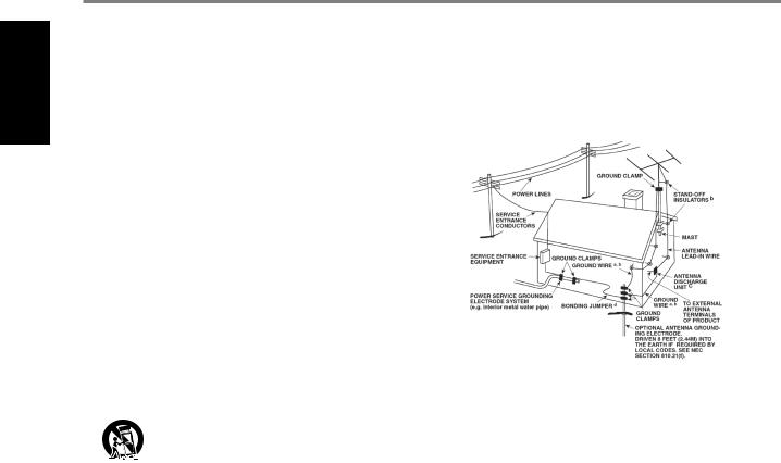
14.Outdoor Antenna Grounding - If an outside antenna or cable system is connected to the product, be sure the antenna or cable system is grounded so as to provide some protection against voltage surges and built-up static charges. Article 810 of the National Electrical Code, ANSI/NFPA 70, provides information with regard to proper grounding of the mast and supporting structure, grounding of the lead-in wire
to an antenna discharge unit, size of grounding conductors, location of antenna discharge unit, connection to grounding electrodes, and requirements for the grounding electrode.
NOTE TO CATV SYSTEM INSTALLER
ThisreminderisprovidedtocalltheCATVsysteminstaller’sattentiontoSection820-40of theNECwhichprovidesguidelinesforpropergroundingand,inparticular,specifiesthat thecablegroundshallbeconnectedtothegroundingsystemofthebuilding,asclose tothepointofcableentryaspractical.
15.Lightning - For added protection for this product during a lightning storm, or when it is left unattended and unused for long periods of time, unplug it from the wall outlet and disconnect the antenna or cable system. This will prevent damage to the product due to lightning and power-line surges.
16.Power Lines - An outside antenna system should not be located in the vicinity of overhead power lines or other electric light or power circuits, or where it can fall into such power lines or circuits. When installing an outside antenna system, extreme care should be taken to keep from touching such power lines or circuits as contact with them might be fatal.
17.Overloading - Do not overload wall outlets, extension cords, or integral convenience receptacles as this can result in a risk of fire or electric shock.
18.Flame Sources - No naked flame sources, such as lighted candles, should be placed on the product.
19.Object and Liquid Entry - Never push objects of any kind into this product through openings as they may touch dangerous voltage points or short-out parts that could result in a fire or electric shock. Never spill liquid of any kind on the product.
20.Headphones - Excessive sound pressure form earphones and headphones can cause hearing loss.
21.Damage Requiring Service - Unplug this product from the wall outlet and refer servicing to qualified service personnel under the following conditions:
a.When the power-supply cord or plug is damaged.
b.If liquid has been spilled, or objects have fallen into the product.
c.If the product has been exposed to rain or water.
d.If the product does not operate normally by following the operating instructions. Adjust only those controls that are covered by the operating instructions as an improper adjustment of other controls may result in damage and will often require extensive work by a qualified technician to restore the product to its normal operation.
e.If the product has been dropped or damaged in any way.
f.When the product exhibits a distinct change in performance-this indicates a need for service.
22.Replacement Parts - When replacement parts are required, be sure the service technician has used replacement parts specified by the manufacturer or have the same characteristics as the original part. Unauthorized substitutions may result in fire, electric shock, or other hazards.
2
IMPORTANT SAFETY INSTRUCTIONS
23.Battery Disposal - When disposing of used batteries, please comply with governmental regulations or environmental public instruction’s rules that apply in your country or area.
24.Safety Check - Upon completion of any service or repairs to this product, ask the service technician to perform safety checks to determine that the product is in proper operating condition.
25.Wall or Ceiling Mounting - The product should be mounted to a wall or ceiling only as recommended by the manufacturer.
WARNING
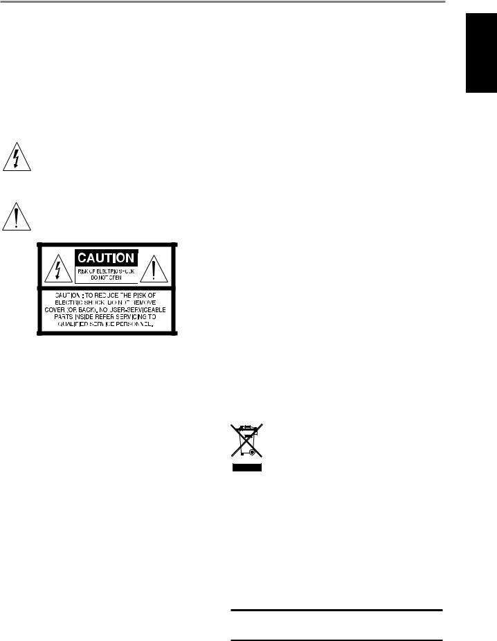
The lightning flash with arrowhead symbol, within an equilateral triangle, is intended to alert the user to the presence of uninsulated “dangerous voltage” within the product’s enclosure that may be of sufficient magnitude to constitute a risk of electric shock to persons
The exclamation point within an equilateral triangle is intended to alert the user to the presence of important operating
and maintenance (servicing) instructions in the literature accompanying the appliance.
THE EQUIPMENT MUST BE CONNECTED TO AN EARTHED MAINS SOCKET-OUTLET.
CAUTION REGARDING PLACEMENT
To maintain proper ventilation, be sure to leave a space around the unit (from the largest outer dimensions including projections) than is equal to, or greater than shown below.
Left and Right Panels: 10 cm Rear Panel: 10 cm
Top Panel: 10 cm
FCC STATEMENT
This equipment has been tested and found to comply with the limits for Class B digital device, pursuant to Part 15 of the FCC Rules. These limits are designed to provide reasonable protection against harmful interference in a residential installation. This equipment generates, uses, and can radiate radio frequency energy and, if not installed and used in accordance with the instructions, may cause harmful interference to radio communications. However, there is no guarantee that interference will not occur in a particular installation. If this
equipment does cause harmful interference to radio or television reception, which can be determined by turning the equipment off and on, the user is encouraged to try to correct the interference by one or more of the following measures:
•Reorient or relocate the receiving antenna.
•Increase the separation between the equipment and receiver.
•Connect the equipment into an outlet on a circuit different from that to which the receiver is connected.
•Consult the dealer or an experienced radio TV technician for help.
CAUTION
Changes or modifications to this equipment not expressly approved by NAD Electronics for compliance could void the user’s authority to operate this equipment.
CAUTION
To prevent electric shock, match wide blade of plug to wide slot, fully insert.
CAUTION
Marking and rating plate can be found at the rear panel of the apparatus.
WARNING
To reduce the risk of fire or electric shock, do not expose this apparatus to rain or moisture.
The apparatus shall not be exposed to dripping or splashing and that no objects filled with liquids, such as vases, shall be placed on apparatus.
Mains plug is used as disconnect device and it should remain readily operable during intended use. In order to disconnect the apparatus from the mains completely, the mains plug should be disconnected from the mains socket outlet completely.
Battery shall not be exposed to excessive heat such as sunshine, fire or the like.
CAUTION
Danger of explosion if battery is incorrectly replaced. Replace only with the same or equivalent type.
An appliance with a protective earth terminal should be connected to a mains outlet with a protective earth connection.
IF IN DOUBT CONSULT A COMPETENT ELECTRICIAN.
This product is manufactured to comply with the radio interference requirements of EEC DIRECTIVE 2004/108/EC.
NOTES ON ENVIRONMENTAL PROTECTION
At the end of its useful life, this product must not be disposed
of with regular household waste but must be returned to a collection point for the recycling of electrical and electronic equipment. The symbol on the product, user’s manual and
packaging point this out.
The materials can be reused in accordance with their markings. Through re-use, recycling of raw materials, or other forms of recycling of old products, you are making an important contribution to the protection of our environment.
Your local administrative office can advise you of the responsible waste disposal point.
RECORD YOUR MODEL NUMBER (NOW, WHILE YOU CAN SEE IT)
The model and serial number of your new M17 are located on the back of the cabinet. For your future convenience, we suggest that you record these numbers here:
Model number : . . . . . . . . . . . . . . . . . . . . . . . . . . . . . . . . . . . . . .
Serial number :. . . . . . . . . . . . . . . . . . . .
NAD is a trademark of NAD Electronics International, a division of Lenbrook Industries Limited Copyright 2015, NAD Electronics International, a division of Lenbrook Industries Limited
ENGLISH
3

ENGLISH
INTRODUCTION
TABLE OF CONTENTS
IMPORTANT SAFETY INSTRUCTIONS . . . . . . . . . . . . . . . . . . . . . . . . . .2
INTRODUCTION
GETTING STARTED. . . . . . . . . . . . . . . . . . . . . . . . 5
WHAT’S IN THE BOX. . . . . . . . . . . . . . . . . . . . . . . . . .5 CHOOSING A LOCATION . . . . . . . . . . . . . . . . . . . . . . . 5 DEFAULT SOURCE SETTINGS . . . . . . . . . . . . . . . . . . . . . 5 RESTORING M17 TO ITS FACTORY DEFAULT SETTINGS.. . . . . . . . 5
IDENTIFICATION OF CONTROLS |
|
FRONT PANEL.. . . . . . . . . . . . . . . . . . . . . . . . . . 6 |
|
REAR PANEL . . . . . . . . . . . . . . . . . . . . . . . . . . . |
8 |
OPERATION |
|
USING THE M17 – MAIN MENU. . . . . . . . . . . . . . . . . |
11 |
ABOUT THE ON-SCREEN DISPLAY (OSD). . . . . . . . . . . . . . |
11 |
MAIN MENU.. . . . . . . . . . . . . . . . . . . . . . . . . . . . |
11 |
LISTENING MODE . . . . . . . . . . . . . . . . . . . . . . . . . . |
11 |
ADJUSTING LISTENING MODES . . . . . . . . . . . . . . . . . . . |
12 |
DSP OPTIONS . . . . . . . . . . . . . . . . . . . . . . . . . . . . |
13 |
TONE CONTROLS.. . . . . . . . . . . . . . . . . . . . . . . . . |
14 |
ZONE CONTROLS. . . . . . . . . . . . . . . . . . . . . . . . . . . . . . . . . . . . . . . . . . . . . . . . . . . |
14 |
USING THE M17 – SETUP MENU . . . . . . . . . . . . . . . . . |
15 |
SETUP MENU. . . . . . . . . . . . . . . . . . . . . . . . . . . . |
15 |
CONTROL SETUP. . . . . . . . . . . . . . . . . . . . . . . . . . |
15 |
SOURCE SETUP . . . . . . . . . . . . . . . . . . . . . . . . . . . |
16 |
SOURCE SETUP (NORMAL VIEW) . . . . . . . . . . . . . . . . . . |
16 |
SOURCE SETUP (TABLE VIEW). . . . . . . . . . . . . . . . . . . |
17 |
SPEAKER SETUP. . . . . . . . . . . . . . . . . . . . . . . . . . . |
18 |
AUDYSSEY AUTO CALIBRATION . . . . . . . . . . . . . . . . . . . |
18 |
SPEAKER CONFIGURATION. . . . . . . . . . . . . . . . . . . . . |
20 |
SPEAKER LEVELS. . . . . . . . . . . . . . . . . . . . . . . . . . |
20 |
SPEAKER DISTANCE . . . . . . . . . . . . . . . . . . . . . . . . . |
21 |
ADJUSTING THE VOLUME . . . . . . . . . . . . . . . . . . . . . . |
21 |
ADJUSTING CHANNEL LEVELS “ON THE FLY’. . . . . . . . . . . . . |
22 |
ZONE SETUP . . . . . . . . . . . . . . . . . . . . . . . . . . . . |
22 |
TRIGGER SETUP . . . . . . . . . . . . . . . . . . . . . . . . . . . |
23 |
LISTENING MODE SETUP. . . . . . . . . . . . . . . . . . . . . . |
23 |
DOLBY SETUP. . . . . . . . . . . . . . . . . . . . . . . . . . . . |
25 |
DTS SETUP . . . . . . . . . . . . . . . . . . . . . . . . . . . . . |
25 |
DTS SURROUND MODES. . . . . . . . . . . . . . . . . . . . . . |
25 |
ENHANCED STEREO. . . . . . . . . . . . . . . . . . . . . . . . . |
26 |
DISPLAY SETUP.. . . . . . . . . . . . . . . . . . . . . . . . . . |
26 |
A/V PRESETS. . . . . . . . . . . . . . . . . . . . . . . . . . . . |
26 |
USING THE HTRM 2 REMOTE CONTROL . . . . . . . . . . . . . . |
30 |
CONTROLLING THE M17. . . . . . . . . . . . . . . . . . . . . . |
30 |
LEARNING CODES FROM OTHER REMOTES.. . . . . . . . . . . . |
31 |
PUNCH THROUGH. . . . . . . . . . . . . . . . . . . . . . . . . |
31 |
COPY A COMMAND FROM ANOTHER KEY.. . . . . . . . . . . . . |
31 |
MACRO COMMANDS . . . . . . . . . . . . . . . . . . . . . . . |
31 |
KEY ILLUMINATION TIMEOUT.. . . . . . . . . . . . . . . . . . . |
32 |
CONFIGURING KEY ILLUMINATION. . . . . . . . . . . . . . . . . |
32 |
FACTORY RESET. . . . . . . . . . . . . . . . . . . . . . . . . . . |
32 |
DELETE MODE. . . . . . . . . . . . . . . . . . . . . . . . . . . |
32 |
LOADING CODE-LIBRARIES. . . . . . . . . . . . . . . . . . . . . |
33 |
SEARCH MODE. . . . . . . . . . . . . . . . . . . . . . . . . . . |
33 |
CHECKING CODE-LIBRARY NUMBER. . . . . . . . . . . . . . . . |
33 |
SUMMARY OF THE HTRM 2 MODES . . . . . . . . . . . . . . . . . |
34 |
USING THE ZR 7 REMOTE CONTROL. . . . . . . . . . . . . . . . . |
34 |
REFERENCE
TROUBLESHOOTING . . . . . . . . . . . . . . . . . . . . . . .35 SPECIFICATIONS. . . . . . . . . . . . . . . . . . . . . . . . .36
THANK YOU FOR CHOOSING NAD. |
|
The M17 AV Surround Sound Preamp Processor is a technologically advanced |
We encourage you to take a few minutes now to read right through this |
and highly capable product — yet we have invested great effort in making it |
manual. Investing a little time here at the outset might save you a good |
simple and easy to use. The M17 delivers a range of genuinely useful options |
deal of time later, and is by far the best way to ensure that you make the |
for surround sound and stereo listening alike, using powerful digital signal |
most of your investment in the M17, and get the most from this powerful |
processing and superbly accurate digital-audio circuitry. However, we have also |
and flexible home-theater component. |
been careful to ensure that the M17 is as musically transparent, faithful to every |
|
video detail and spatially accurate as possible, incorporating much of what |
One more thing: We urge you to register your M17 ownership on the NAD |
we’ve learned from a quarter-century’s experience designing audio, video and |
Worldwide Web site: |
home-theater components. As with all our products, NAD’s“Music First” design |
|
philosophy guided the M17’s design, such that it can confidently promise you |
http://NADelectronics.com/salon |
both state-of-the-art surround home-theater and audiophile-quality music |
|
listening for years to come. |
For warranty information contact your local distributor. |
NAD SHALL NOT BE HELD LIABLE FOR ANY TECHNICAL OR USER INTERFACE DISCREPANCIES IN THIS MANUAL. THE M17 OWNER’S MANUAL MAY BE SUBJECT TO CHANGE WITHOUT PRIOR NOTICE. CHECK OUT THE NAD WEBSITE FOR THE LATEST VERSION OF THE M17 OWNER’S MANUAL.
4
|
|
|
INTRODUCTION |
|
|
|
GETTING STARTED |
|
|
|
|
WHAT’S IN THE BOX |
|
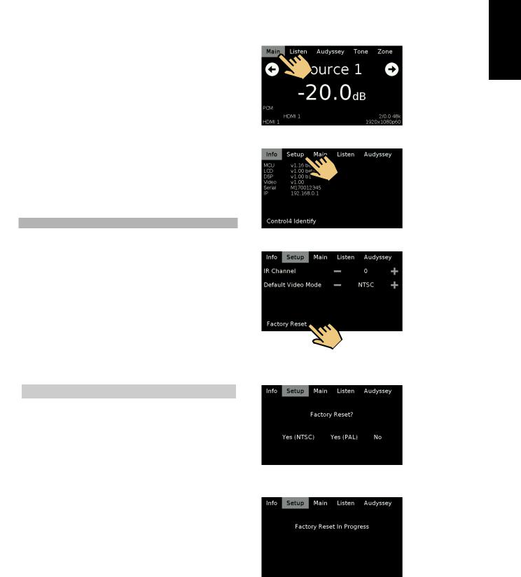
RESTORING M17 TO ITS FACTORY DEFAULT SETTINGS |
|
Packed with your M17 you will find |
|
1 Press |
panel’s “Main” display. |
•A detachable mains power cord
• Audyssey microphone
•3.5mm female jack to RCA plug Adapter for Audyssey microphone input
•HTRM 2 remote control with 4 AA batteries
•ZR 7 zone remote control with 3V CR2025 battery
•Four pieces of magnetic feet
•Cleaning cloth
•USB flash drive
•Quick Setup Guide
2 Select “Setup” |
. |
SAVE THE PACKAGING |
|
Please save the box and all of the packaging in which your M17 arrived. |
|
Should you move or otherwise need to transport your M17, this is by far the |
|
safest container in which to do so. We’ve seen too many otherwise perfect |
|
components damaged in transit for lack of a proper shipping carton, so |
|
please: Save that box! |
|
CHOOSING A LOCATION
Choose a location that is well ventilated (with at least several inches to |
|
|
|
both sides and behind), and that will provide a clear line of sight, within |
3 |
Select “Factory Reset” display option. |
|
25 feet / 8 meters, between the M17’s front panel and your primary |
|
|
|
listening/viewing position—this will ensure reliable infrared remote control |
|
|
|
communications. The M17 generates a modest amount of heat, but |
|
|
|
nothing that should trouble adjacent components. |
|
|
|
It is perfectly possible to stack the M17 on top of other components, but |
|
|
|
the reverse usually should be avoided. |
|
|
|
|
|
|
|
DEFAULT SOURCE SETTINGS |
|
|
|
The following table lists the default SOURCE settings. Note that the Audio |
|
|
|
input settings show both digital and analog audio input. Digital input will |
|
|
|
always take precedence over analog audio input even if both are present. |
4 |
Select between |
“Yes (PAL) to select video mode after |
|
|
Factory Reset. Select “No” if you decide not to reset your M17. |
|
Source |
Audio Input |
Video Input |
Source 1 |
HDMI 1/Audio 1 IN |
HDMI 1 |
Source 2 |
HDMI 2/Audio 2 IN |
HDMI 2 |
Source 3 |
HDMI 3/Audio 3 IN |
HDMI 3 |
Source 4 |
HDMI 4/Audio 4 IN |
HDMI 4 |
Source 5 |
Optical 1 IN/Audio 5 IN |
Video 1 IN |
Source 6 |
Optical 2 IN/Audio 6 IN |
Video 2 IN |
Source 7 |
Coaxial 1 IN/Audio 6 IN |
Video 3 IN |
Source 8 |
Optical 3 IN |
Component Video Input 1 |
Source 9 |
Coaxial 2 IN |
Component Video Input 2 |
|
|
|
To modify the above default settings and for a better understanding of source setting and combinations, please refer to the item about “SOURCE SETUP” in the “USING THE M17 - SETUP MENU” segment of the “OPERATION” section.
5Factory reset is complete after the display below and the M17 going to standby mode.
ENGLISH
5
ENGLISH
IDENTIFICATION OF CONTROLS
FRONT PANEL
1
AV SURROUND SOUND PREAMP PROCESSOR |
M17 |
|
|
|
|
|
|
|
|
|
|
|
|
|
|
|
|
|
|
|
|
|
|
|
|
|
|
|
|
|
|
|
|
|
|
|
|
|
|
© NAD M17 |
|
|
|
|
|
|
|
|
|
|
|
|
|
|
|
|
|
|
|
|
|
|
|
|
|
|
|
|
|
|
|
|
|
|
|
|
|
|
|
|
|
|
|
|
|
|
|
|
|
|
|
|
|
|
|
|
|
|
|
|
|
|
|
|
|
|
|
|
|
|
|
|
|
|
|
|
|
|
|
|
|
|
|
|
|
|
|
|
|
|
|
|
|
|
|
|
|
|
|
|
|
|
|
|
|
|
|
|
|
|
|
|
|
|
|
|
|
|
|
|
|
|
|
|
|
|
|
|
|
|
|
|
|
|
|
|
|
|
|
|
|
|
|
|
|
|
|
|
|
|
|
|
|
|
|
|
|
|
|
|
|
|
|
|
|
|
|
|
|
|
|
|
|
|
|
|
|
|
|
|
|
|
|
|
|
|
|
|
|
|
|
|
|
|
|
|
|
|
|
|
|
|
|
|
|
|
|
|
|
|
|
|
|
|
|
|
|
|
|
|
|
|
|
|
|
|
|
|
|
|
|
|
|
|
|
|
|
|
|
|
|
|
|
|
|
|
|
|
|
|
|
|
|
|
|
|
|
|
|
|
|
|
|
|
|
|
|
|
|
|
|
|
|
|
|
|
|
|
|
|
|
|
|
|
|
|
|
|
|
|
|
|
|
|
|
|
|
|
|
|
|
|
|
|
|
|
|
|
|
|
|
|
|
|
|
|
|
|
|
|
|
|
|
|
|
|
|
|
|
|
|
|
|
|
|
|
|
|
|
|
|
|
|
|
|
|
|
|
|
|
|
|
|
|
|
|
|
|
|
|
|
|
|
|
|
|
|
|
|
|
|
|
|
|
|
|
|
|
|
|
|
|
|
|
|
|
|
|
|
|
|
|
|
|
|
|
|
|
|
|
|
|
|
|
|
|
|
|
|
|
|
|
|
|
|
|
|
||||||||||||
|
|
|
|
|
|
|
|
|
|
|
|
|
|
|
|
|
|
|
|
|
|
|
|
|
||||||||||||||
|
|
2 |
|
|
|
3 |
|
|
|
|
|
|
4 |
|
|
|
5 |
|
|
|
||||||||||||||||||
1 o(STANDBY) |
|
|
|
|
|
|
|
|
|
|
|
|
|
4 DISPLAY |
||||||||||||||||||||||||
• Press o(Standby) button for the M17 to be switched ON from |
|
|
|
|
|
• Show visual and menu information according to the display settings |
||||||||||||||||||||||||||||||||
standby mode. The Power indicator will turn from amber to bright/ |
|
|
|
|
|
|
selected. |
|||||||||||||||||||||||||||||||
white color. |
|
|
|
|
|
|
|
|
|
|
|
|
|
|
|
|
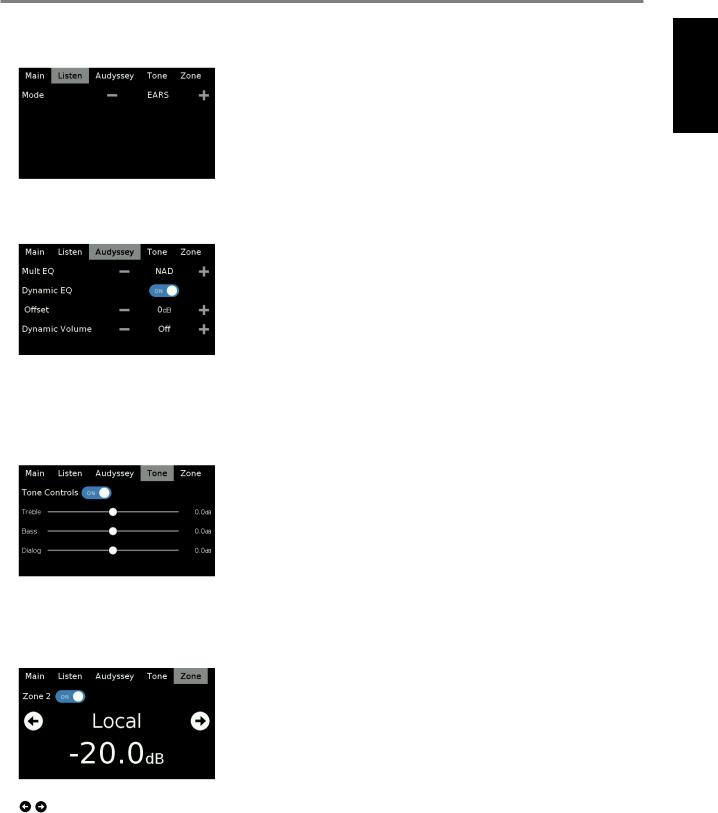
• There are four display options – Main, Listen, Audyssey, Tone and |
|||||||||||||||||||||
• Pressing o(Standby) button again switches back M17 to standby |
|
|
|
|
|
|
Zone. |
|||||||||||||||||||||||||||||||
mode. The Power indicator will illuminate to amber color at standby |
|
|
|
|
|
• Use your finger to press and select any of these display options to |
||||||||||||||||||||||||||||||||
mode. |
|
|
|
|
|
|
|
|
|
|
|
|
|
|
|
|
|
show their corresponding menu options or settings. |
||||||||||||||||||||
•The o(Standby) button cannot activate the M17 with the rear
panel POWER switched off. |
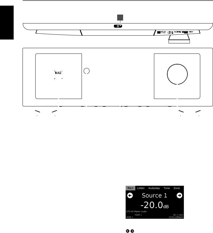
The following are sample screenshots of the four display options with |
|
corresponding description of the information shown. |
IMPORTANT NOTES |
|
• Refer also to +12V TRIGGER IN (OFF/AUTO) of IDENTIFICATION OF |
MAIN |
CONTROLS - REAR PANEL. |
|
•For the o(Standby) button to activate, two conditions must be completed.
a Plug-in the supplied mains power cord to a mains power source. Connect corresponding end of the mains power cord to the AC mains input of M17 and the plug connected to a mains power source.
b The rear panel POWER switch must be set to ON position.
2 |
POWER INDICATOR |
Source 1: Current Source. |
|
• This indicator will light up amber when the M17 is at standby mode. |
-20.0 dB: Volume level. |
|
• When the M17 is powered up from standby mode, this indicator will |
: Go to previous or next Source. |
|
turn from amber to bright/white color. |
DTS-HD Master Audio: Audio Codec - Detected audio stream format. |
|
|
HDMI 1/HDMI 1: Audio and video input source. |
3 |
REMOTE SENSOR |
3/2.1 192k: Audio Source format; sample rate. |
|
• Point the HTRM 2 remote control at the remote sensor and press the |
1920x1080p60: Video mode - Video resolution of current source with |
|
buttons. |
frame rate. |
|
• Do not expose the remote sensor of the M17 to a strong light |
|
|
source such as direct sunlight or illumination. If you do so, you may |
|
|
not be able to operate the M17 with the remote control. |
|
Distance: About 23ft (7m) from the front of the remote sensor.
Angle: About 30o in each direction of the front of the remote sensor.
6
IDENTIFICATION OF CONTROLS
FRONT PANEL
LISTEN
EARS: Listening mode.
- +: Go to previous or next Listening mode.
AUDYSSEY
-/+: Go to previous or next option.
 : Slide to turn ON or OFF Dynamic EQ.
For descriptions of the above item, refer to sections about DSP OPTIONS and AUDYSSEY CALIBRATION.
TONE
 : Slide to turn ON or OFF Tone Controls. At OFF setting, tone controls are disabled or defeated.
h: Slide to adjust treble, bass or dialog level.
ZONE
 : Slide to turn ON or OFF Zone 2. : Go to previous or next Source.
5VOLUME
•Use this control to adjust the overall loudness of the signal output at AUDIO PRE-OUT.
•The default volume level is -20dB.
ENGLISH
7

IDENTIFICATION OF CONTROLS
REAR PANEL
ENGLISH |
|
|
|
|
|
|
|
|
|
|
|
|
|
1 |
|
|
|
|
2 |
3 |
|
4 |
|
5 |
|
|
|
|
|
|
|
|
|
|
|
|
|
|
|
|
|
|
|
|
|||||
|
|
R |
|
L |
R |
|
L |
|
R |
L |
AUDIO PRE-OUT BALANCED |
AUDIO PRE-OUT |
|
CENTER |
|
|
|
|
|
|
||||
|
|
|
|
|
|
|
|
|
|
|
|
|
|
|
|
|
|
|
|
IR |
|
+12V TRIGGER |
||
|
|
|
|
|
|
|
|
|
|
|
|
|
|
L |
|
|
L |
|
|
|
|
|||
|
|
|
|
|
|
|
|
|
|
|
|
|
|
|
|
|
|
|
+12V TRIGGER IN |
OUT 1 |
OUT 2 |
OUT 1 |
OUT 2 |
|
|
|
|
|
|
|
|
|
|
|
|
|
|
|
R |
|
|
R |
|
OFF |
AUTO |
|
|
|
|
|
|
|
|
|
|
|
|
|
|
|
|
|
|
|
|
|
|
|
|
|
|
|
||
|
|
|
|
|
|
|
|
|
|
|
|
|
|
|
SURR |
SURR-B |
SUBW1 SUBW2 |
|
RS232 |
IN |
|
|
|
|
|
|
FRONT |
|
|
|
SURR |
|
|
SURR-B |
|
CENTER |
SUBW |
FRONT |
|
|
|
|
|
|
|||||
FRANÇAIS |
IN |
IN |
IN |
OUT |
IN |
OUT |
IN |
IN |
IN |
OUT |
|
|
2 DIGITAL AUDIO IN |
|
1 |
DIGITAL AUDIO OUT |
|
OUT 4 |
OUT 3 |
IN |
OUT 3 |
|||
|
|
|
|
|
|
POWER |
|
|||||||||||||||||
L |
|
|
|
|
|
|
|
|
|
|
1 |
1 |
2 |
3 |
4 |
|
1 |
2 |
|
|
|
|
||
|
|
|
|
|
|
|
|
|
|
|
|
|
|
|
|
|
|
|
|
|
|
|
||
|
|
|
|
ZONE 3 |
|
ZONE 4 |
|
|
|
|
|
|
4 |
|
|
2 |
|
|
|
|
|
|
|
ON |
|
|
|
|
|
|
|
|
|
|
|
|
|
|
|
|
|
|
|
|
|
||||
|
|
|
|
|
|
|
|
|
|
|
|
|
|
|
|
|
|
|
|
|
|
|
||
|
R |
|
|
|
|
|
|
|
|
|
|
3 |
|
|
|
|
|
|
|
|
|
|
|
|
|
AUDIO 1 |
AUDIO 2 |
AUDIO 3 |
AUDIO 4 |
AUDIO 5 |
AUDIO 6 |
AUDIO 7 |
ZONE 2 |
|
COAXIAL IN |
|
OPTICAL IN |
COAXIAL OUT |
OPTICAL OUT |
|
|
|
|
|
|||||
|
|
|
|
|
|
|
|
|
|
|
|
|
|
|
||||||||||
|
|
|
|
|
COMPONENT VIDEO INPUT 1 |
MONITOR OUT ZONE 2 |
|
|
LAN |
HDMI 4 |
HDMI 5 |
|
HDMI 6 |
|
|
|
|
120V~60Hz |
|
|||||
|
|
|
|
|
|
|
|
|
|
|
|
|
|
|||||||||||
|
|
|
|
|
|
|
|
|
|
|
|
|
|
|
|
|
|
|
|
UNSWITCHED AC OUTLET |
|
|
|
|
|
|
|
|
|
Y |
CB/PB |
CR/PR |
|
|
|
|
|
|
HDMI, the HDMI logo and High-Definition Multimedia Interface are trademarks |
|
|
|
|
|
|||||
|
|
|
|
|
|
|
|
|
|
|
|
|
|
or registered trademarks of HDMI Licensing LLC. |
|
|
|
|
|
|
|
|||
|
|
|
|
|
|
|
|
|
|
|
|
|
|
HDMI 1 |
HDMI 2 |
|
HDMI 3 |
|
|
|
|
|
|
|
|
1 |
2 |
3 |
|
|
|
|
Y |
CB/PB |
CR/PR |
|
MONITOR OUT 1 |
MONITOR OUT 2 |
|
|
|
|
|
120V~60Hz 120W 1A MAX |
|
|
|
||
|
|
VIDEO INPUT |
|
VIDEO OUT COMPONENT VIDEO INPUT 2 |
MONITOR OUT |
|
|
|
|
|
|
|
|
|
|
|||||||||
ESPAÑOL |
© NAD M17 |
|
|
|
|
|
|
|
|
|
|
|
|
|
|
|
|
|
|
|
|
|
|
|
|
|
|
|
|
|
|
|
8 |
|
10 |
11 |
|
|
|
|
|
|
|
|
|
|
|
|
|
|
|
|
|
|
|
|
|
|
|
|
|
|
|
|
|
|
|
|
|
|
|
|||
|
IN |
IN |
IN |
OUT |
IN |
OUT |
IN |
IN |
IN |
OUT |
|
|
|
|
|
|
|
|
|
|
|
|
|
|
|
L |
|
|
|
|
|
|
|
|
|
|
|
|
|
|
|
|
|
|
|
|
|
|
|
|
6 |
|
|
ZONE 3 |
|
ZONE 4 |
|
|
|
|
9 |
|
|
|
|
|
12 |
|
13 |
|
|
14 |
15 |
|
|
R |
|
|
|
|
|
|
|
|
|
|
|
|
|
|
|
|
|
|
|
|
|
|
|
AUDIO 1 AUDIO 2 |
AUDIO 3 |
AUDIO 4 |
AUDIO 5 |
AUDIO 6 AUDIO 7 ZONE 2 |
|
COMPONENT VIDEO INPUT 1 |
MONITOR OUT ZONE 2 |
||
|
7 |
|
|
|
|
Y |
CB/PB |
CR/PR |
|
ITALIANO
SVENSKA NEDERLANDS DEUTSCH
РУССКИЙ
1 |
2 |
3 |
Y |
CB/PB |
CR/PR |
|
VIDEO INPUT |
VIDEO OUT COMPONENT VIDEO INPUT 2 |
|
MONITOR OUT |
|
ATTENTION!
Please make sure that the M17 is powered off or unplugged from the mains power source before making any connections. It is also advisable to power down or unplug all associated components while making or breaking any signal or AC power connections.
1AUDIO PRE-OUT (BALANCED)
•The AUDIO PRE-OUT makes it possible to use the M17 as a preamplifier to external power amplifiers for some or all channels.
•Depending upon the source’s configuration, analog audio output connection can be made up to seven channels either via BALANCED or SINGLE-ENDED output ports.
•Use the AUDIO PRE OUT (BALANCED) if the external source to be connected has BALANCED audio input. Superior audio quality is ensured with the distinctive noise reduction capability of BALANCED connection with XLR jacks.
•Connect FRONT L, FRONT R, CENTER, SURR R, SURR L, SURR-BL and SURR-BR to the respective channel input of a power amplifier or amplifiers driving the corresponding applicable speakers.
•Connect the SUBW output to powered (“active”) subwoofers or to power amplifier channels driving a passive system.
AUDIO PRE OUT (SINGLE-ENDED)
•Use single-ended AUDIO PRE OUT for sources that are not equipped with BALANCED analog audio input.
2RS 232
NAD is a certified partner of AMX and Crestron and fully supports these external devices. Check out the NAD website for information about AMX and Crestron compatibility with NAD. See your NAD audio specialist for more information.
•Connect this interface using RS-232 serial cable (not supplied) to any Windows compatible PC to allow remote control of the M17 via compatible external controllers.
•Refer to the NAD website for information about RS232 Protocol documents and PC interface program.
3+12V TRIGGER IN (OFF/AUTO)
•The settings of +12V TRIGGER IN (OFF/AUTO) together with +12V TRIGGER (IN) (item 5) affect the manner on how the M17 can be switched ON from standby mode or back to standby mode.
+12V TRIGGER IN (AUTO)
•If +12V TRIGGER IN (OFF/AUTO) is set to AUTO, pressing the front panel o (Standby) button or HTRM 2’s ON/OFF button cannot switch ON the M17 from standby mode and vice-versa. Both control buttons are effectively disabled thereby handling the function of powering up the M17 to an external controller.
•If +12V TRIGGER IN (OFF/AUTO) is set to AUTO, powering up the M17 is dependent upon the “Auto Trigger In” setting at the “Trigger Setup” menu as well as the absence or presence of +12V at +12V TRIGGER (IN)(item 5).
+12V TRIGGER IN (OFF)
•Slide the +12V TRIGGER IN (OFF/AUTO) switch to OFF for the M17 to be normally switched ON from standby mode and vice-versa using the front panel o (Standby) button or HTRM 2’s ON/OFF button.
•The +12V TRIGGER (IN) (item 5) is disabled with +12V TRIGGER IN (OFF/AUTO) set to OFF.
8

IDENTIFICATION OF CONTROLS
REAR PANEL
Below is a table of sample combination settings with respect to switching ON the M17 from standby mode and vice versa.
+12V |
+12V |
AUTO |
FRONT |
HTRM2(ON/ |
M17POWER |
TRIGGERIN |
TRIGGER(IN) |
PANEL |
|||
(OFF/AUTO) |
(item5) |
TRIGGERIN |
o(STANDBY) |
OFF) |
MODESTATE |
|
|
|
|
|
|
AUTO |
+12V |
Main, All |
ON |
ON |
Operating |
|
|
|
|
|
mode |
AUTO |
+12V |
Main, All |
OFF |
OFF |
Operating |
|
|
|
|
|
mode |
AUTO |
0V |
Main, All |
ON/OFF |
ON/OFF |
Standby |
|
|
|
|
|
mode |
AUTO |
0V |
Zone 2, |
ON |
ON |
Operating |
|
|
Zone 3 or |
|
|
mode |
|
|
Zone 4 |
|
|
|
AUTO |
0V |
Zone 2, |
OFF |
OFF |
Standby |
|
|
Zone 3 or |
|
|
mode |
|
|
Zone 4 |
|
|
|
OFF |
+12V |
Any |
ON |
ON |
Operating |
|
or 0V |
setting |
|
|
mode |
OFF |
+12V |
Any |
OFF |
OFF |
Standby |
|
or 0V |
setting |
|
|
mode |
5+12V TRIGGER OUT1/OUT2/OUT3
The M17 has three +12V TRIGGER OUT ports (OUT 1, OUT2 and OUT3) that can be configured to supply +12V DC to a linked component or system. See discussion on “Trigger Setup” at the “Setup Menu” literature for guidelines on how to configure +12V TRIGGER IN/OUT.
•Use a 3.5mm mini-jack connector to pass +12 volts at a maximum current of 50 milliamps to an auxiliary equipment such as a multichannel amplifier or subwoofer. The center conductor (hot) of the 3.5mm jack is the control signal. The outside conductor (shield) is the ground return-path.
•This output will be 12V when the M17 is ON and 0V when the unit is either OFF or in standby mode.
+12V TRIGGER IN
With this input triggered by a 12V DC supply, the M17 can be switched ON remotely from standby mode by compatible devices such as amplifiers, preamplifiers, receivers, etc. If the 12V DC supply is cut off, the M17 will return to standby mode.
•Connect this +12V TRIGGER INPUT to the remote device’s corresponding +12V DC output jack using a mono cable with 3.5mm male plug. The controlling device must be equipped with a +12V trigger output to use this feature.
4 IR IN/IR OUT 1-4 |
|
These mini-jacks accept and output remote-controlled codes in |
6 AUDIO 1-7 IN/VIDEO INPUT 1-3 |
electrical format, using industry-standard protocols, for use with “IR- |
• These comprise the M17’s other sets of principal input. Connect |
repeater” and multi-room systems and related technologies. |
these audio and video input ports to corresponding output ports of |
• All NAD products with IR IN/IR OUT features are fully compatible |
compatible source components such as DVD players, CD players or |
with the M17. For non-NAD models, please check with your other |
cable/satellite boxes. |
product’s service specialists with respect to their compatibility to |
• AUDIO 5 IN, AUDIO 6 IN and AUDIO 7 IN are ideal for the connection |
the M17’s IR features. |
of the analog output of line-level audio sources like a CD player or |
|
Stereo tuner. |
IR IN |
• The Left Channel of AUDIO 1 IN is the assigned port where the |
• This input is connected to the output of an IR (infrared) repeater |
supplied 3.5mm female jack to RCA plug Adapter can be connected. |
(Xantech or similar) or the IR output of another compatible device |
Plug in the Audyssey microphone into the adapter for Audyssey |
to allow control of the M17 from a remote location. |
Auto Calibration. |
IR OUT 1- 4 |
AUDIO 3-4 OUT/VIDEO OUT |
• Connect IR OUT 1 (or IR OUT 2/IR OUT 3/IR OUT 4) to the IR IN jack of |
• Connect AUDIO 3 OUT (and/or AUDIO 4 OUT) to corresponding |
a compatible device. |
recording components or audio/video input ports of compatible |
• Command and control the linked compatible device by directing its |
sources like cassette deck, CD/DVD recorder or outboard audio |
own remote control to M17’s infrared receiver. |
processors. |
|
• The signal present at AUDIO 3 OUT is determined by the current |
IR IN and IR OUT 1/IR OUT 2/IR OUT 3/IR OUT 4 |
source selected. There will be no output at AUDIO 3 OUT when |
• Connect the M17’s IR IN to the IR OUT of a compatible device. |
AUDIO 3 is selected. Likewise, there will be no output at AUDIO |
Connect also the M17’s IR OUT 1 (or IR OUT 2/IR OUT 3/IR OUT 4) to |
4 OUT when AUDIO 4 is the active source input. This prevents |
the IR IN of a compatible device. |
feedback through the recording component thereby preventing |
• With this setup, the M17 acts as an “IR-repeater” allowing the device |
possible damage to your speakers. |
connected to the M17’ s IR IN control or command of the other |
• When configured, AUDIO 3 OUT and AUDIO 4 OUT are the same |
device linked to M17’s IR OUT 1 (or IR OUT 2/IR OUT 3/IR OUT 4). |
assigned ports for Zone 3 and Zone 4 respectively. See also Zone |
|
output description below. |
|
7 COMPONENT VIDEO INPUT 1-2, |
|
COMPONENT VIDEO MONITOR OUT |
|
• |
•
•
ENGLISH
9

ENGLISH
IDENTIFICATION OF CONTROLS
REAR PANEL
8MONITOR OUT (COMPOSITE VIDEO)
•Connect to the video input of a monitor/television using quality dual-RCA connectors designed for video signals.
9ZONE 2-3-4
•The M17 has three configurable Zones – Zone 2, Zone 3 and Zone 4. The Zone feature allows one to simultaneously experience in
a different zone or location of the house a Source assigned to a particular zone.
•Send zone selected audio and video output to the corresponding audio and video input of another zone. Use high quality patch cables to reduce noise pickup over long distance runs.
•For a better understanding of zone settings, study below the section about “Zone Controls” of the “Main Menu” discussion as well as the item about “Zone Setup” under the “Setup Menu” literatures.
NOTES
•“Zone 4” is audio only and not associated with any video input sources.
•Zone 2 and Zone 3 video output are available only if the corresponding zone’s video source is composite video.
10DIGITAL AUDIO IN (COAXIAL IN 1-4, OPTICAL IN 1-4)
•Connect to the corresponding optical or coaxial digital output of sources such as CD or BD/DVD players, digital cable box, digital tuners and other applicable components.
•Coaxial and Optical digital input association is configurable via the Source Setup item of the Setup Menu OSD.
DIGITAL AUDIO OUT (COAXIAL OUT 1-2, OPTICAL OUT 1-2)
•Connect the optical or coaxial DIGITAL AUDIO OUT to the corresponding digital audio input of compatible devices such as receivers, computer soundcard or other digital processors.
11ETHERNET/LOCAL AREA NETWORK (LAN) PORT
LAN connection must be setup for wired connection to be established. Set up a Wired Ethernet broadband router with broadband internet connection. Your router or home network should have a built-in DHCP server to consummate the connection.
•With Ethernet connection established, you can now control the M17 using the NAD AVR Remote App that can be downloaded from the Apple App store to your iOS device (iPhone, iPad or iPod Touch). Ensure that your iOS device with the NAD AVR Remote App is connected to the same network as the M17.
•The NAD AVR Remote App automatically discovers your networkconnected M17 and walks you through controlling and adjusting fundamental functions including power, volume, source selection and other basic setup features.
•The IP address of your network-connected M17 can be obtained. Press and hold “Main” item in the front panel display menu until below information is displayed.
NOTES
•NAD is not responsible for any malfunction of the M17 and/or the internet connection due to communication errors or malfunctions associated with your broadband internet connection or other connected equipment. Contact your Internet Service Provider (ISP) for assistance or the service bureau of your other equipment.
•Contact your ISP for policies, charges, content restrictions, service limitations, bandwidth, repair and other related issues pertinent to internet connectivity pertinent to internet connectivity.
12HDMI (HDMI IN 1-6, HDMI MONITOR OUT 1-2)
•Connect the sets of HDMI input to the HDMI OUT connectors of source components such as DVD player, BD player or HDTV satellite/ cable box.
•Connect the HDMI MONITOR OUT 1 and/or HMDI MONITOR OUT 2 to compatible HDTV or projector with HDMI input. Both HDMI output ports display simultaneously the same audio/video source.
WARNING
Before connecting and disconnecting any HDMI cables, both the M17 and the ancillary source must be powered OFF and unplugged from the AC outlet. Failure to observe this practice may cause permanent damage to all equipment connected via HDMI sockets.
13UNSWITCHED AC OUTLET (120V version model only)
•With M17 switched ON or at standby mode, mains power is always available at this outlet.
•This outlet can be used for components that may require continuous supply of AC mains; some tuners require uninterrupted mains supply to retain preset memory, for instance.
•The total draw of all devices connected to this outlet must not exceed 120 watts.
•Mains power at this outlet can be shut down by switching OFF the M17 via the rear panel POWER switch.
14AC MAINS INPUT
•The M17 comes supplied with a separate detachable mains power cord. Before connecting the plug to the mains power source, connect firmly first the other end to M17’s AC Mains input socket.
•Always disconnect the mains power plug from the mains power source first, before disconnecting the cable from the M17’s AC Mains input socket.
•Connect only to the prescribed AC outlet, i.e., 120V 60 Hz (for 120V version models only) or 230V 50 Hz (for 230V version models only).
15POWER
•Supply the AC mains power to the M17.
•When the POWER switch is set to ON position, the M17 goes to standby mode as shown by the amber status condition of the front panel Power indicator. Press the front panel o (Standby) button or HTRM 2 remote control’s [ON] button to switch ON the M17 from standby mode.
•If you intend not to use the M17 for long periods of time (such as when on vacation), switch off the POWER switch. With POWER switched off, neither the front panel o (Standby) button nor HTRM 2 remote control’s [ON] button can activate the M17.
10
OPERATION
USING THE M17 – MAIN MENU
ABOUT THE ON-SCREEN DISPLAY (OSD) |
LISTENING MODE |
The M17 employs a simple, self-explanatory system of on-screen display “menus” that will appear on the connected video monitor/TV. These are required during the setup process (and are useful in day-to-day operation), so be sure to connect the monitor/TV before proceeding with setup.
DISPLAY THE OSD
Press [E] or [ENTER] buttons of the HTRM 2 remote control to display the M17’s Main Menu on your video monitor/TV. If the OSD does not appear, check your MONITOR OUT connections.
NAVIGATING THE OSD AND MAKING CHANGES
To navigate through the OSD menu options, please do the following using the HTRM 2 buttons:
1Press [E] to select a menu item. Use [R/T] or in some cases, [ENTER], to move up or down the Menu selections. Repeatedly press [E] to advance or go further into the sub-menu of desired menu item.
2Use [R/T] to set or change the parameter value (setting) of a menu item.
3Press [W] to save the settings or changes done on the current menu or sub-menu. Pressing [W] will also return the user to the previous menu or exit from a particular menu.
MAIN MENU
The Main Menu contains the menu options for “Listening Mode”, “DSP Options”, “Tone Controls”, “Zone Controls” and access to “Setup Menu”.
Follow the guidelines about “DISPLAY THE OSD” and “NAVIGATING THE OSD AND MAKING CHANGES” to navigate through the menu options and their sub-menu selections.
NOTE
The individual configurations set forth at “Listening Mode”, “DSP Options” and “Tone Controls” are carried over whenever they are enabled at A/V Presets setting. Please see the section “AV PRESETS” for reference.
The M17 offers distinct listening modes, tailored for different types of recording or program material. With a two-channel (Stereo) source, the following listening modes can be selected.
IMPORTANT NOTICE
The M17 is an AV Surround Sound Preamplifier and therefore has no speakers. The mention of “Speaker(s)” in this manual refers to the speakers of your external amplifier as interfaced with the M17.
STEREO
All output is directed to the front left/right channels. Low frequencies are directed to the subwoofer if one is present in the Speaker settings. Select “Stereo” when you wish to listen to a stereo (or monaural) production, such as music CD or FM broadcast, without surround enhancement. Stereo recordings whether in PCM/digital or analog form and whether surroundencoded or not encoded, are reproduced as recorded. Multi-channel digital recordings (Dolby Digital and DTS) are reproduced in “Stereo Downmix” mode via the front left/right channels only as Lt/Rt (left/right-total) signals.
DIRECT
Analog or digital sources are automatically played in their native formats. All the source’s audio channels are reproduced directly. This mode recreates the original sound most faithfully thereby producing outstandingly high quality audio.
DIRECT listening mode is selectable only during source playback. In order to setup DIRECT as preferred listening mode, the following steps have to be undertaken.
1Go to LISTENING MODE SETUP under SETUP MENU. Select LISTENING MODES. Under LISTENING MODES menu, set to “None” all the parameter settings for Dolby, DTS, PCM and Analog.
2Then, go to A/V PRESETS items under SETUP MENU. Scroll to LISTENING MODE item and set to “Yes”. Store this LISTENING MODE setting to Preset 1 along with the other parameter settings by clicking “Save Current Setup to Preset”.
3This saved “Preset 1” setting can now be associated to any Source. Below is a sample association.
a Under SOURCE SETUP (Normal View), go to SOURCE 1 and scroll down to A/V Preset and set “A/V Preset” to “Preset 1”.
b Now, whenever SOURCE 1 is recalled with “Preset 1” associated to it, the LISTENING MODE setting will always be DIRECT.
PRO LOGIC
Two-channel recordings, whether stereo or surround-encoded, are reproduced with Dolby Pro Logic surround processing, yielding output to front left/right, center and discrete left/right surround channels (assuming these are present in the current “Speaker Configuration”). The surround channel is monophonic, but it is reproduced in both surround speakers.
ENGLISH
11
ENGLISH
OPERATION
USING THE M17 – MAIN MENU
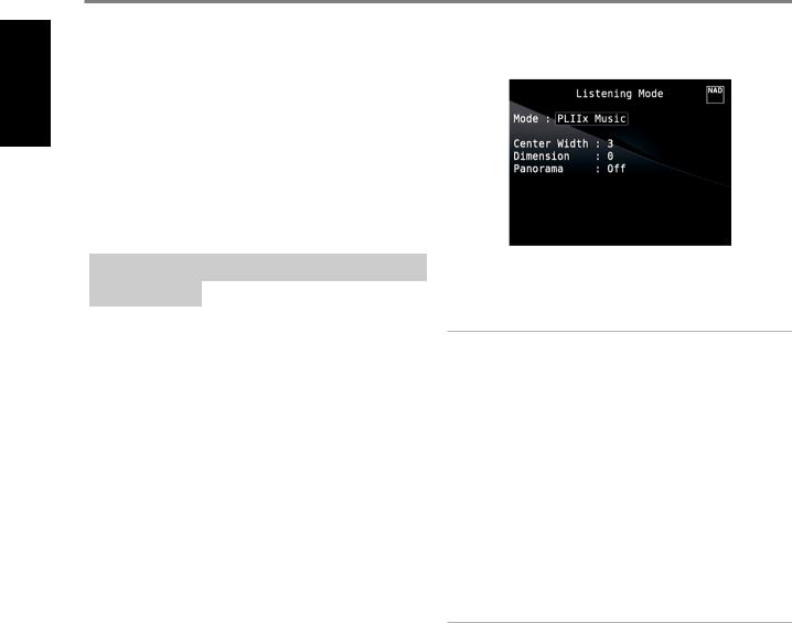
DOLBY PRO LOGIC IIx |
ADJUSTING LISTENING MODES |
Dolby Pro Logic IIx processes both stereo and 5.1 signals into a 6.1 or 7.1 |
|
channel output. At Dolby Pro Logic IIx, you can choose PLIIx Movie or PLIIx |
|
Music modes to tailor your listening experience to the source material. |
|
Dolby Pro Logic IIx surround processing yields more stable imaging and full |
|
bandwidth sound to the rear channels in Movie mode offering sound that is |
|
more similar to Dolby Digital decoding. For two channel signals, PLIIx Music |
|
mode also features three additional user controls - Dimension, Center Width, |
|
and Panorama. See also section about“Adjusting Listening Modes” below. |
|
The following chart shows the channels available assuming they are |
|
enabled in the “Speaker Configuration” menu: |
|
Listening Mode |
Active Decoded Output Channels |
|
|
|
|
Two-Channel Sources |
6.1 Speaker System |
7.1 Speaker System |
|
||
|
|
|
|
Front (left, right), |
Front (left, right), Center, |
PLIIx Music |
Center, Surround (left, |
Surround (left, right) |
PLIIx Movie |
right), Back Surround, |
and Back Surround (left, |
|
Subwoofer |
right), Subwoofer |
DTS NEO: 6
Two-channel recordings, whether stereo or surround-encoded, are reproduced with Neo: 6 surround with output to front left/right, center and discrete left/right surround channels plus subwoofer (assuming these are present in the current “Speaker Configuration”). The M17 provides two DTS Neo: 6 variations - NEO:6 Cinema and NEO:6 Music. See also section about “Adjusting Listening Modes” below.
EARS
Two-channel recordings, whether stereo or surround-encoded, are reproduced with proprietary NAD surround processing with signals output to the front left/right, center and discrete left/right surround channels, plus subwoofer (assuming these are present in the current “Speaker Configuration”). EARS does not employ the surround back speakers (if any).
EARS extracts the natural ambience present in nearly all well-produced stereo recordings. It does not synthesize any ambience or other sonic elements and thus remains truer to the sound of the original musical performance than most other music-surround options.
Select EARS for listening to stereo music recordings and broadcasts. EARS produces a subtle but highly natural and believable ambience from nearly all “natural-acoustic” stereo recordings. Typically, these include classical, jazz, and folk genres as well as numerous examples from others. Its virtues include realistic, stable “front-stage” sonic imaging and spacious but unexaggerated ambient “virtual acoustics” that remain faithful to the original recording.
ENHANCED STEREO
All recordings are reproduced in stereo via the maximum speaker complement configured in the current “Speaker Configuration”. Enhanced stereo can be useful for maximum volume from all channels or for multispeaker background music (cocktail party) listening. For this mode, Front, Center, Surround and Back speakers can be turned ON/OFF as desired.
Several of the M17’s listening modes have one or more selectable variations and adjustable parameters that you can modify to suit your system or personal preferences.
NOTE
Listening Mode parameter changes are maintained when you change listening modes. You may also save a modified Listening Mode for easy recall by saving it to a Preset (See “A/V Presets” below under Setup Menu discussions).
PRO LOGIC IIx
PLIIx MOVIE is optimized for film soundtracks. PLIIx MUSIC for music recordings
Center Width (0 to 7): Modifies the “hard-centeredness” of the center image, by gradually mixing mono center content to the Front left/right speakers as well. A setting of 0 retains the center-channel-only default while a setting of 7 yields a fully phantom center channel.
Dimension (-7 to +7): Adjusts front-rear emphasis of the surround effect independently from the relative channel levels.
Panorama (On/Off): Adds a “wraparound” effect by extending some stereo content into the surround channels.
NOTE
Pro Logic IIx mode will decode as PLII mode when the BACK surround speakers are set to “OFF” from “Speaker Configuration” menu. See also section about “Speaker Configuration” under “Speaker Setup” of the Setup Menu.
DTS NEO: 6
NEO: 6 Cinema is optimized for film soundtracks. NEO: 6 Music for music recordings
Center Gain (0 to 0.5): Adjust for better center image in relation to the surround sound channels.
12
Loading...