

Page 1

be certain.
m
Axial Extensometers
Product Information
100-006-162 E
Page 2

Copyright information
Trademark information
Publication information
Manual Part Number Publication Date
100-006-162 A August 1999
100-006-162 B January 2000
100-006-162 C December 2000
© 1999, 2000, 2005, 2008, 2009 MTS
Systems Corporation. All rights reserved.
MTS, TestStar, and TestWare are
registered trademarks of MTS Systems
Corporation within the United States.
These trademarks may be protected in
other countries.
100-006-162 C
100-006-162 D March 2008
100-006-162 E June 2009
* Format change to smaller size to accommodate packaging. No
technical content was changed.
February 2005
*
Page 3

Technical Support 5
How to Get Technical Support 5
Before You Contact MTS 6
If You Contact MTS by Phone 7
Problem Submittal Form in MTS Manuals 9
Preface 11
Before You Begin 11
Documentation Conventions 12
Introduction 15
Axial Extensometer Functional Description 17
About DC Conditioning 17
About Wheatstone Bridge 18
Transducer Calibration 19
Axial Extensometer Overtravel Protection 19
Extensometer Zero Reference 20
Axial Extensometer Accessories 20
Contents
3
Page 4

Configuration 23
About Quick Attachment Spring Installation 23
How to Install Anchored Springs 24
How to Install an Attachment Adapter 25
How to Install Sliding Springs 26
How to Install Extension Springs or Elastic Bands 30
How to Change Knife Edges 32
About Gage Lengths 35
How to Use Gage Length Extenders 35
How to Use Gage Length De-Extenders 37
How to Connect the Cable 38
Calibration 41
Calibration Overview 41
Certified Calibration 41
Gain 41
Delta K 42
Symmetrical versus Asymmetrical Extensometers 42
How to Use a Vernier Caliper 43
How to Use a Calibration Block 46
How to Use a Calibration Stand 47
Installation 51
Zero Extensometer Output 51
How to Mount an Extensometer 52
About Quick Attachment Springs 53
How to Adjust the Sliding Spring Length 54
How to Select an Anchor Position 56
About Metal Extension Springs 57
Extension Spring Table 58
About Elastic Bands 60
4
Page 5

Technical Support
How to Get Technical Support
Start with your manuals
The manuals supplied by MTS provide most of the information you
need to use and maintain your equipment. If your equipment includes
MTS software, look for online help and README files that contain
additional product information.
If you cannot find answers to your technical questions from these
sources, you can use the internet, e-mail, telephone, or fax to contact
MTS for assistance.
Technical support methods
MTS provides a full range of support services after your system is
installed. If you have any questions about a system or product, contact
MTS in one of the following ways.
MTS web site www.mts.com
The MTS web site gives you access to our technical support staff by
means of a Technical Support link:
www.mts.com > Contact Us > Service & Technical Support
E-mail
techsupport@mts.com
Telephone
MTS Call Center 800-328-2255
Weekdays 7:00 A.M. to 5:00 P.M., Central Time
Fax
952-937-4515
Please include “Technical Support” in the subject line.
Technical Support
5
Page 6

Before You Contact MTS
MTS can help you more efficiently if you have the following
information available when you contact us for support.
Know your site number and system number
The site number contains your company number and identifies your
equipment type (material testing, simulation, and so forth). The number
is usually written on a label on your MTS equipment before the system
leaves MTS. If you do not have or do not know your MTS site number,
contact your MTS sales engineer.
Example site number: 571167
When you have more than one MTS system, the system job number
identifies which system you are calling about. You can find your job
number in the papers sent to you when you ordered your system.
Example system number: US1.42460
Know information from prior technical assistance
If you have contacted MTS about this problem before, we can recall
your file. You will need to tell us the:
• MTS notification number
• Name of the person who helped you
Identify the problem
Describe the problem you are experiencing and know the answers to the
following questions:
• How long and how often has the problem been occurring?
• Can you reproduce the problem?
• Were any hardware or software changes made to the system before
the problem started?
• What are the model numbers of the suspect equipment?
• What model controller are you using (if applicable)?
• What test configuration are you using?
6
Technical Support
Page 7

Know relevant computer information
If you are experiencing a computer problem, have the following
information available:
• Manufacturer’s name and model number
• Operating software type and service patch information
• Amount of system memory
• Amount of free space on the hard drive in which the application
resides
• Current status of hard-drive fragmentation
• Connection status to a corporate network
Know relevant software information
For software application problems, have the following information
available:
• The software application’s name, version number, build number,
and if available, software patch number. This information is
displayed briefly when you launch the application, and can
typically be found in the “About” selection in the “Help” menu.
• It is also helpful if the names of other non-MTS applications that
are running on your computer, such as anti-virus software, screen
savers, keyboard enhancers, print spoolers, and so forth are known
and available.
If You Contact MTS by Phone
Your call will be registered by a Call Center agent if you are calling
within the United States or Canada. Before connecting you with a
technical support specialist, the agent will ask you for your site number,
name, company, company address, and the phone number where you
can normally be reached.
If you are calling about an issue that has already been assigned a
notification number, please provide that number. You will be assigned a
unique notification number about any new issue.
Technical Support
7
Page 8

Identify system type
To assist the Call Center agent with connecting you to the most qualified
technical support specialist available, identify your system as one of the
following types:
• Electromechanical materials test system
• Hydromechanical materials test system
• Vehicle test system
• Vehicle component test system
• Aero test system
Be prepared to troubleshoot
Prepare yourself for troubleshooting while on the phone:
• Call from a telephone when you are close to the system so that you
can try implementing suggestions made over the phone.
• Have the original operating and application software media
available.
• If you are not familiar with all aspects of the equipment operation,
have an experienced user nearby to assist you.
Write down relevant information
Prepare yourself in case we need to call you back:
• Remember to ask for the notification number.
• Record the name of the person who helped you.
• Write down any specific instructions to be followed, such as data
recording or performance monitoring.
After you call
MTS logs and tracks all calls to ensure that you receive assistance and
that action is taken regarding your problem or request. If you have
questions about the status of your problem or have additional
information to report, please contact MTS again and provide your
original notification number.
8
Technical Support
Page 9

Problem Submittal Form in MTS Manuals
Use the Problem Submittal Form to communicate problems you are
experiencing with your MTS software, hardware, manuals, or service
which have not been resolved to your satisfaction through the technical
support process. This form includes check boxes that allow you to
indicate the urgency of your problem and your expectation of an
acceptable response time. We guarantee a timely response—your
feedback is important to us.
The Problem Submittal Form can be accessed:
• In the back of many MTS manuals (postage paid form to be mailed
to MTS)
• www.mts.com > Contact Us > Problem Submittal Form (electronic
form to be e-mailed to MTS)
Technical Support
9
Page 10

10
Technical Support
Page 11

Preface
Before You Begin
Safety first!
Before you attempt to use your MTS product or system, read and
understand the Safety manual and any other safety information provided
with your system. Improper installation, operation, or maintenance of
MTS equipment in your test facility can result in hazardous conditions
that can cause severe personal injury or death and damage to your
equipment and specimen. Again, read and understand the safety
information provided with your system before you continue. It is very
important that you remain aware of hazards that apply to your system.
Other MTS manuals
In addition to this manual, you may receive additional MTS manuals in
paper or electronic form.
If you have purchased a test system, it may include an MTS System
Documentation CD. This CD contains an electronic copy of the MTS
manuals that pertain to your test system, including hydraulic and
mechanical component manuals, assembly drawings and parts lists, and
operation and preventive maintenance manuals. Controller and
application software manuals are typically included on the software CD
distribution disc(s).
Preface
11
Page 12

Conventions
DANGER
WARNING
CAUTION
Documentation Conventions
The following paragraphs describe some of the conventions that are
used in your MTS manuals.
Hazard conventions
As necessary, hazard notices may be embedded in this manual. These
notices contain safety information that is specific to the task to be
performed. Hazard notices immediately precede the step or procedure
that may lead to an associated hazard. Read all hazard notices carefully
and follow the directions that are given. Three different levels of hazard
notices may appear in your manuals. Following are examples of all
three levels.
Note For general safety information, see the safety information
provided with your system.
Danger notices indicate the presence of a hazard with a high level of risk
which, if ignored, will result in death, severe personal injury, or
substantial property damage.
Notes
12
Warning notices indicate the presence of a hazard with a medium level
of risk which, if ignored, can result in death, severe personal injury, or
substantial property damage.
Caution notices indicate the presence of a hazard with a low level of risk
which, if ignored, could cause moderate or minor personal injury,
equipment damage, or endanger test integrity.
Notes provide additional information about operating your system or
highlight easily overlooked items. For example:
Preface
Page 13

Note Resources that are put back on the hardware lists show up at
the end of the list.
Special terms
The first occurrence of special terms is shown in italics.
Illustrations
Illustrations appear in this manual to clarify text. It is important for you
to be aware that these illustrations are examples only and do not
necessarily represent your actual system configuration, test application,
or software.
Electronic manual conventions
This manual is available as an electronic document in the Portable
Document File (PDF) format. It can be viewed on any computer that has
Adobe Acrobat Reader installed.
Hypertext links
The electronic document has many hypertext links displayed in a blue
font. All blue words in the body text, along with all contents entries and
index page numbers, are hypertext links. When you click a hypertext
link, the application jumps to the corresponding topic.
Preface
13
Page 14

14
Preface
Page 15
Introduction
MODEL
632.27
l
l
MODEL
634.31
l
MODEL
634.12
l
MODEL
632.26
l
632.29F-30
Opt. 001
MODEL
632.13
l
MODEL
632.11
l
This manual describes the MTS axial extensometer family. Axial
extensometers measure changes along the length of a specimen. Axial
extensometers are suitable for a variety of static and dynamic testing
applications including tension/compression testing, low and high cycle
fatigue, creep/stress relaxation testing, and strain rate testing. Several
accessories are available such as gage length extenders, gage length deextenders, knife edges, and attachment methods. Not all accessories are
available for all models.
Contents
Axial Extensometer Functional Description 17
Axial Extensometer Accessories 20
Introduction
Assorted Extensometers
15
Page 16

What you need to know
This manual assumes that you know how to use your system controller.
See the appropriate manual for information about performing any
controller-related step in this manual’s procedures. You are expected to
know how to:
• Select a control mode.
• Manually adjust the actuator position.
• Zero a sensor output.
• Install a specimen.
Related documentation
This manual covers topics that are common among all axial
extensometers. Specific information about a given extensometer is
available from the drawings that are included with it.
Each extensometer may include the following documents:
• An installation drawing provides the specifications for your
extensometer. It also includes detailed drawings and notes related
to setting up and installing the extensometer.
16
• A Final Inspection card provides information such as the serial
number, as tested excitation voltage, and other performance data.
• An Extensometer Calibration Data sheet is included when MTS
calibrates the extensometer.
• You may have drawings for optional kits for your extensometer.
These drawings include specifications and installation information
for the given option.
• You may have a model application drawing that lists the family of
extensometers for the model number you purchased. It lists the
specification differences among the extensometer family. The
drawing also includes the part number of the installation drawing
for your extensometer and the wiring diagram of the connector.
This manual is designed to be used with these documents.
Introduction
Page 17
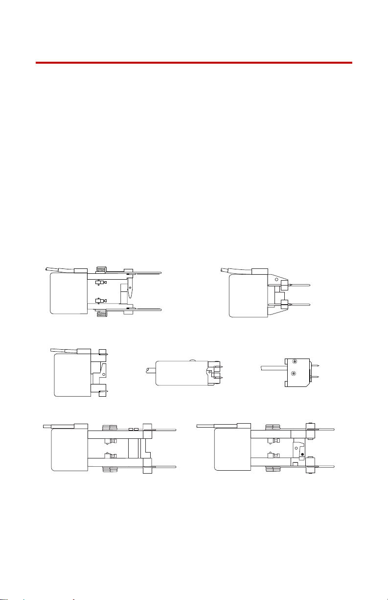
Axial Extensometer Functional Description
Δ
An axial extensometer is a sensor attached to a specimen that measures
a dimensional change (gage length or strain) that occurs in the specimen
while being tested. Extensometers use a Wheatstone bridge circuit to
detect the dimensional changes. Because they are DC devices, they
require a DC conditioner for signal processing. The following
paragraphs describe the functions of the axial extensometers.
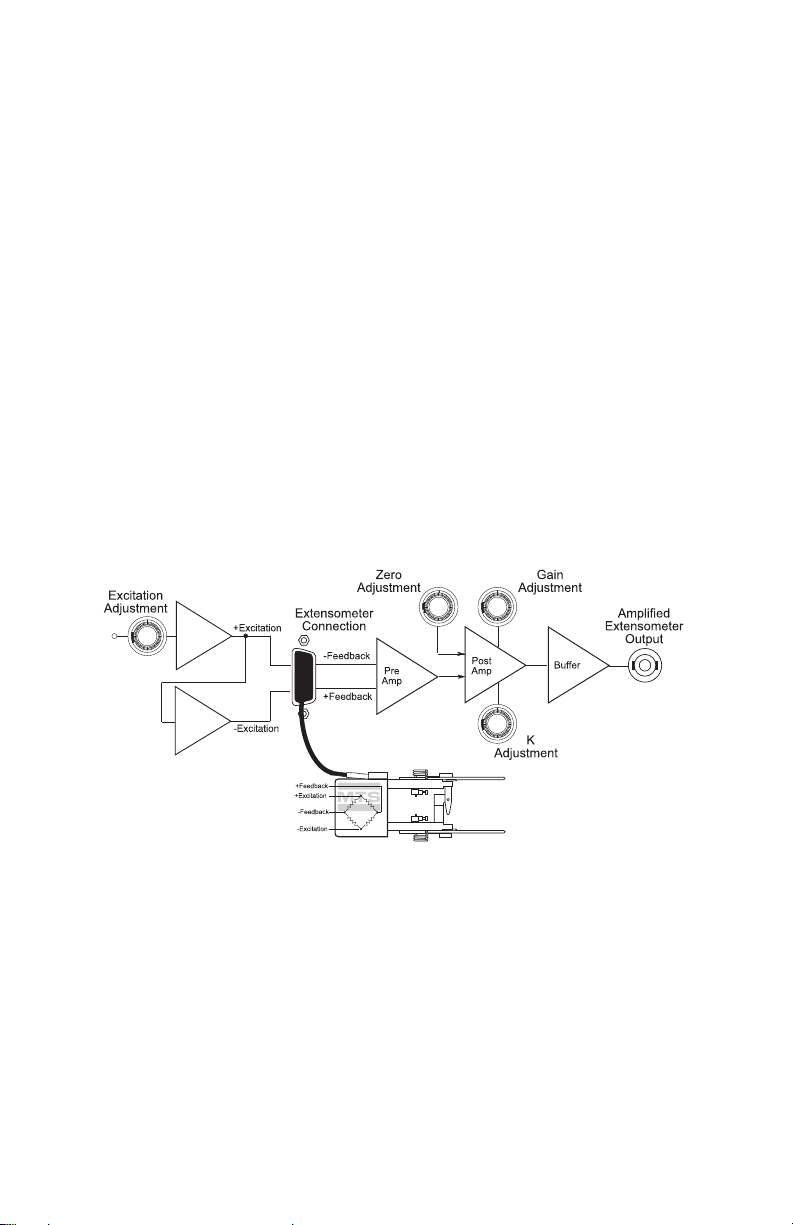
About DC Conditioning
The transducer requires a DC conditioner to process the transducer
signal. A DC conditioner provides a DC excitation voltage to the
transducer. Any changes to the gage length of the transducer change the
excitation signal. The changed signal is output to the DC conditioner as
feedback. The DC conditioner processes the signal and makes it
available to the controller where the signal may be used.
Introduction
Typical Conditioning Circuit
17
Page 18
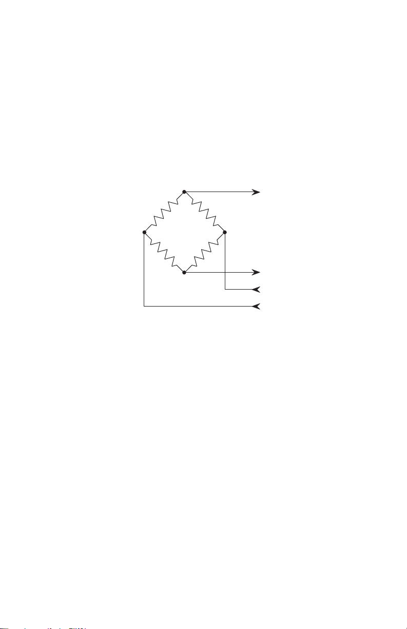
About Wheatstone Bridge
Feedback
Excitation
Sensor
Bridge
The axial transducer uses precision, resistance-type, foil strain gages
bonded to a metallic element to form a Wheatstone bridge. Two knife
edges on the transducer arms contact the specimen. Elongation or
compression of the specimen causes movement of the transducer arms.
This movement bends the metallic element, changing the resistance of
the strain gages. The change in the balance of the Wheatstone bridge
produces an electrical output that is proportional to the displacement of
the transducer arms.
18
Introduction
Page 19
Transducer Calibration
Δ
Overtravel
Blocks
Zero Stop
Upper Arm
Lower Arm
The DC conditioner and the transducer signal must be calibrated.
Calibration ensures that the transducer signal accurately represents the
gage length measure by the transducer. Calibration involves adjusting
the excitation voltage and gain of the DC conditioner to achieve the
desired transducer signal. The purpose of calibration is to equate a
specific transducer displacement to a specific voltage. When the
transducer is calibrated, it is matched to a DC conditioner. If either
component of the matched pair is changed, recalibration is required.
Axial Extensometer Overtravel Protection
Introduction
When a specimen fails, the extensometer arms can be subjected to
movement beyond the rated travel. Overtravel protection is
accomplished with a pair of overtravel blocks. One block limits the
tension travel and the other limits the compressive travel to the rated
range of the extensometer.
19
Page 20

Extensometer Zero Reference
There are three zero reference methods used by MTS’s extensometers:
zero pin, zero stop, and fixture. The zero reference position is important
when calibrating the extensometer output signal or when mounting an
extensometer to a specimen.
Zero pin
Some extensometers includes a zero pin that can be inserted into a zero
reference hole. This locks the extensometer arms in the zero reference
position. This is useful for specimen installation.
Zero stop
Some extensometers include a zero stop block built into the arms of the
extensometer. A zero stop block works like overtravel blocks. When
installing a specimen, pinch the two arms of the extensometer together.
This stops the extensometer’s arms in the zero position.
Fixture
Some extensometers require special fixtures that set the arms of the
extensometer into the proper zero reference positon.
Axial Extensometer Accessories
20
Note Not all accessories are available for all extensometers. Check
with MTS Systems Corporation for a list of possible accessories
for your extensometer.
Accessories available for the axial extensometers include the following:
• Gage length extenders increase the gage length of the extensometer
without changing its travel. An extension bracket is mounted to one
arm of an extensometer to increase the gage length.
• Gage length de-extenders decrease the gage length of the
extensometer without changing its travel. De-extender hardware is
mounted to both arms of an extensometer to decrease the gage
length.
• Cable connectors from the extensometer can be an Amphenol or a
PT connector.
• A Model 650.03 Extensometer Calibrator can help with the local
calibration of any extensometer.
Introduction
Page 21

• A variety of knife edges allow the extensometer to be used with
different specimen shapes:
– Straight knife edge sets for round specimens. Kits are
available for standard, heavy duty, and extended length
straight knife edges.
– Three-point contact knife edge sets for flat specimens. Kits
are available for standard, heavy duty, and extended length
three-point contact knife edges.
• Specimen attachment kits offer a variety of extensometer mounting
options:
– Quick attachment springs are available in shapes that allow an
extensometer to easily clip onto a flat or round specimen.
– Elastic bands are available in different lengths to
accommodate different specimen dimensions. Elastic bands
should be used at room temperatures.
– Metal extension springs are available in different lengths to
accommodate different specimen dimensions. Metal springs
can be used over a range of temperatures.
Introduction
21
Page 22

22
Introduction
Page 23

Configuration
This section describes how to configure an axial extensometer with
quick attachment springs, elastic bands, or metal extension springs. It
also describes how to change the knife edges, gage length of the
extensometer, and how to connect it to a controller.
Contents
About Quick Attachment Spring Installation 23
How to Install Extension Springs or Elastic Bands 30
How to Change Knife Edges 32
About Gage Lengths 35
How to Connect the Cable 38
Configuring an extensometer
Each extensometer includes tools and special fittings to configure the
extensometer for a variety of uses. To configure an extensometer,
determine the following and perform the appropriate installation
procedures.
• Type of specimen mounting
• Type of knife edges
• Gage length
After you have configured the extensometer you need to perform the
following:
• Connect the cable to your controller.
• Calibrate the extensometer.
About Quick Attachment Spring Installation
Quick attachment springs let you quickly and easily mount an
extensometer to a specimen. The shape of the springs depends on the
extensometer model. This section includes two procedures to install the
quick attachment springs. Some extensometers use anchored springs
while others use sliding springs.
Configuration
23
Page 24

Excessive torque on the extensometer arms can damage the
CAUTION
m
MODEL
xxx.xxx-xx
Spring
Socket Head Cap
Screws (2)
Spring
Retainer
Attachment
Adapter
(optional)
extensometer.
The extensometer arms can be damaged when mishandled.
Do not hold the extensometer case when loosening or tightening the
socket head cap screws. Use an adjustable wrench to hold the
extensometer arm or attachment adapter. Loosen or tighten only those
socket head cap screws on the arm being held with the wrench.
How to Install Anchored Springs
Perform the following procedure to install the anchored quick
attachment springs on an extensometer. They can be also be installed
onto gage length extenders.
24
Quick Attachment Spring Mounting
The extensometer arms have several anchor holes for the spring. The
holes allow the extensometer to be mounted on specimens of different
thicknesses. See the installation drawing that came with your
extensometer for information about which anchor hole should be used
for a given specimen thickness.
Configuration
Page 25

1. Check your installation drawing. If your extensometer needs an
Hex Wrench
Adjustable
Wrench
attachment adapter, perform the appropriate procedure before
proceeding.
2. Separate the spring retainers from the springs by loosening (do not
remove) the socket head cap screws.
3. Mount one spring in the appropriate hole in the attachment adapter
as determined by the specimen dimensions (see the installation
drawing).
4. Slide the spring retainer over the end of the spring and tighten the
socket head cap screw. Orient the spring retainer in such a way that
it will not interfere with movement of the extensometer arm.
5. Select the matching spring and repeat Step 3 and Step 4 for the
other extensometer arm.
How to Install an Attachment Adapter
Some extensometers do not have anchor holes in their upper and lower
arms and require attachment adapters to be mounted. Others may need
an attachment adapter when an extender is used.
1. Zero the arms of the extensometer. Depending on the extensometer,
this can be accomplished using the zero pin, stop block, or a special
fixture.
.
Configuration
25
Page 26

2. Using a small adjustable wrench, grasp the sides of the upper arm.
Upper
Attachment
Adapter
Lower
Attachment
Adapter
Socket Head
Cap Screws
Front View
Knife Edges
Knife Edge
Hold-Down
and
Attachment Hook
Knife Edge
Hold-Down
and
Attachment Hook
(Top View)
(Bottom View)
Sliding springs
are mounted
here.
3. Loosen the socket head cap screws with a hex wrench.
4. Repeat Step 2 and Step 3 to loosen the socket head cap screws on
the lower arm.
5. With the attachment hook in place, loosely attach the quick
attachment spring attachment adapter to the extensometer arm.
Repeat this step for the other arm.
6. Slide the selected knife edge under the attachment adapter and
between the two socket head cap screws on each extensometer arm.
• Use straight knife edges for round specimens. If straight knife
edges are being used, place the flat surface of a machinist’s
square or similar object across the face of both knife edges to
ensure that they are parallel to each other.
• Use three-point knife edges for flat specimens. Ensure that the
single-point contact knife edge is in the upper arm and the
two-point contact knife edge is in the lower arm.
7. Tighten the socket head cap screws on both extensometer arms.
How to Install Sliding Springs
26
Installing the sliding quick attachment springs on an extensometer
involves removing the existing knife edge hold-down from each arm of
the extensometer and replacing it with the adapter attachment.
Configuration
Page 27

Slide Spring Components
Hex Wrench
Adjustable
Wrench
1. Zero the arms of the extensometer. Depending on the extensometer,
this can be accomplished using the zero pin, stop block, or a special
fixture.
2. Using a small adjustable wrench, grasp the sides of the upper arm.
.
3. While securely holding the extensometer arm, loosen the socket
head cap screws with a hex wrench.
4. Repeat Step 2 and Step 3 to loosen the socket head cap screws on
the lower arm.
5. Remove the knife edge hold-downs, knife edges, and attachment
hooks by removing both socket head cap screws from each
extensometer arm.
6. Loosely attach the upper and lower attachment adapters to the
7. Slide the knife edge between the extensometer arm and the
8. Tighten the socket head cap screws only enough to secure the knife
9. Insert the alignment rod into the attachment adapter as shown in
Configuration
respective extensometer arm using the socket head cap screws
removed in Step 5.
attachment adapter and between the two socket head cap screws.
• Use straight knife edges for round specimens.
• Use three-point knife edges for flat specimens. Ensure that the
single-point contact knife edge is in the upper arm and the
two-point contact knife edge is in the lower arm.
edges.
the Attachment Adapter Alignment figure.
27
Page 28

10. Place one edge of a machinist’s square against the front edge of the
Perpendicular
Alignment of
Rod and Square
90
o
Slider
Spring
Attachment
Adapter
Square
Square with the flat
surface against the
upper alignment rod.
Alignment
Rod
Vertical Alignment of
Alignment Rod
Adjust the lower
attachment adapter until
the alignment rod rests
against the square.
top extensometer arm. Adjust the attachment adapter until the
alignment rod contacts the perpendicular edge of the square.
.
11. To align the alignment rods vertically, place the flat surface of the
machinist’s square against the alignment rod in the upper
attachment adapter. Adjust the lower attachment adapter until both
alignment rods are resting against the surface of the square.
28
Attachment Adapter Alignment
12. If straight knife edges are being used, place the flat surface of the
machinist’s square across the face of both knife edges to ensure
that both edges are parallel to each other.
13. Being careful not to change the attachment adapter alignment, use
a small adjustable wrench to grasp the attachment adapter.
Configuration
Page 29

.
Grasp the attachment
adapter with a small
adjustable wrench
when using the hex
wrench.
Attachment
Adapter
Hex Wrench
14. While securely holding the attachment adapter, fully tighten the
socket head cap screws in that arm of the extensometer with a hex
wrench.
15. Repeat Step 13 and Step 14 to tighten the other attachment adapter.
16. Remove the alignment rod from the attachment adapter. Insert the
selected spring type (as determined by the shape of the specimen—
round or flat) in each attachment adapter.
Configuration
29
Page 30

How to Install Extension Springs or Elastic Bands
m
MODEL
xxx.xxx-xx
Extension
Spring
Attachment Hook
Upper Arm
Lower Arm
CAUTION
Installing the extension spring or elastic band attachment system
involves replacing the quick attachment spring attachment adapters on
each arm of the extensometer with knife edge hold-downs and
attachment hooks.
Component Identification
30
Excessive torque on the extensometer arms can damage the
extensometer.
The extensometer arms can be damaged when mishandled.
Do not hold the extensometer case when loosening or tightening the
socket head cap screws. Use an adjustable wrench to hold the
extensometer arm or attachment adapter. Loosen or tighten only those
socket head cap screws on the arm being held with the wrench.
The attachment hooks are usually always installed between the knife
edge and knife hold-down on each arm of the extensometer. Depending
on the model of the extensometer and the type of mounting required, the
hooks are sometimes removed.
Configuration
Page 31

To install the attachment hooks:
Hex Wrench
Adjustable
Wrench
1. Zero the arms of the extensometer. Depending on the extensometer,
this can be accomplished using the zero pin, stop block, or a special
fixture.
2. Using a small adjustable wrench, grasp the sides of the upper arm.
3. While securely holding the extensometer with the wrench, loosen
the socket head cap screws with a hex wrench.
4. Repeat Step 2 and Step 3 to loosen the socket head cap screws on
5. Remove the knife edge holddown and knife edge by removing both
6. Slide the knife edge between the extensometer arm and the knife
7. Place the attachment hook between the upper knife edge hold-
Configuration
the lower extensometer arm.
socket head cap screws from each extensometer arm.
edge hold-down.
• Use straight knife edges for round specimens.
• Use three-point knife edges for flat specimens. Ensure that the
single-point contact knife edge is in the upper arm and the
two-point contact knife edge is in the lower arm.
down of the upper extensometer arm knife edge.
31
Page 32

8. Loosely attach the upper knife edge hold-down to the upper
Straight Knife Edge Three-Point Knife Edge Set
Top
Bottom
634
632
634
632
634
632
extensometer arm using the two socket head cap screws removed
in Step 5. Ensure that the attachment hook is behind both socket
head cap screws.
9. Repeat Step 7 and Step 8 for the lower arm.
10. Tighten the socket head cap screws only enough to secure the knife
edges.
11. If straight knife edges are being used, place the flat surface of a
machinist’s square or similar object across the face of both knife
edges to ensure that both edges are parallel to each other.
12. Use a small adjustable wrench to grasp the sides of the upper arm.
13. While securely holding the extensometer arm, fully tighten the
socket head cap screws with a hex wrench.
14. Repeat Step 12 and Step 13 to tighten the socket head cap screws
on the lower arm.
How to Change Knife Edges
Knife edges are available in straight or three-point contact sets:
• Straight knife edges are used for testing round specimens.
• Three-point contact knife edges are used for testing flat
specimens. One knife edge has a single point and the other
knife edge has two points.
Note The knife edges for the Series 632 Extensometers and the
Series 634 Extensometers are not interchangeable. The
differences are shown in the following figure.
32
Configuration
Page 33

Knife edges are available in the standard size, in a heavy duty size, and
Heavy DutyStandard
CAUTION
Hex Wrench
Adjustable
Wrench
in an extended length size. The heavy duty and extended length knife
edges are approximately twice as thick as the standard ones. To
maintain the proper gage length, the contact edge is off center. Heavy
duty and extended length knife edges also require special knife edge
hold-downs or special attachment adapters for quick attachment springs.
Extended length knife edges provide more clearance between the
specimen and the ends of the extensometer arms.
Excessive torque on the extensometer arms can damage the
extensometer.
The extensometer arms can be damaged when mishandled.
Do not hold the extensometer case when loosening or tightening the
socket head cap screws. Use an adjustable wrench to hold the
extensometer arm or attachment adapter. Loosen or tighten only those
socket head cap screws on the arm being held with the wrench.
Configuration
To change knife edges:
1. Zero the arms of the extensometer. Depending on the extensometer,
this can be accomplished using the zero pin, stop block, or a special
fixture.
2. Use a small adjustable wrench to grasp the upper arm or
attachment adapter.
33
Page 34

3. While securely holding the extensometer arm or attachment
Heavy DutyStandard
Hold Down
Knife Edge
Cap Screw
Upper Arm
adapter, loosen the socket head cap screws with a hex wrench just
enough to remove the knife edges.
4. Repeat Step 2 and Step 3 to loosen the socket head cap screws in
the lower arm.
5. Slide out the existing knife edge.
Note When using heavy duty or extended length knife edges, the
contact edges are off center to maintain the proper gage length.
The orientation of the knife edges will vary depending on the
extensometer model being used. See the knife edge installation
drawing that accompanied the knife edge kit for the proper
orientation.
.
6. Slide the knife edge between the extensometer arm and the knife
edge hold-down or attachment adapter
34
• Use straight knife edges for round specimens.
• Use three-point knife edges for flat specimens. Ensure that the
single-point contact knife edge is in the upper arm and the
two-point contact knife edge is in the lower arm.
7. Tighten the socket head cap screws only enough to secure the knife
edges.
If straight knife edges are being used, place the flat surface of a
machinist’s square or similar object across the face of both knife
edges to ensure that both edges are parallel to each other.
Configuration
Page 35

8. If necessary, use a small adjustable wrench to grasp the sides of one
m
MODEL
xxx.xxx-xx
m
MODEL
xxx.xxx-xx
m
MODEL
xxx.xxx-xx
Some extenders
are mounted from
the top.
Clamp
Some extenders
are mounted from
the top and the
bottom.
Quick Attachment Adapter
(only needed if the quick
attachment spring is to be
used)
Extender
Knife Edge
Cap Screw
Hold-Down
extensometer arm or attachment adapter (see the figure in Step 2).
9. While securely holding the extensometer arm or attachment
adapter, fully tighten the socket head cap screws in that arm with a
hex wrench.
10. Repeat Step 8 and Step 9 to tighten the socket head cap screws in
the other extensometer arm.
About Gage Lengths
The gage length of an extensometer can be changed by installing gage
length extenders or gage length de-extenders. Changing the gage length
does not change the travel of the extensometer.
How to Use Gage Length Extenders
Gage length extenders let you change where the extensometer contacts
the specimen. The following figure shows several of the most common
methods to install gage length extenders.
Configuration
35
Page 36

The following procedure describes a typical gage length extender
installation. Actual installation may vary, see the installation drawing
accompanying the gage length extender for specific details.
1. Zero the arms of the extensometer. Depending on the extensometer,
this can be accomplished using the zero pin, stop block, or a special
fixture.
2. Remove the existing knife edge hold-down or quick attachment
adapter from the upper arm of the extensometer. Take care not to
loosen the spring attachment hooks and knife edges.
Note A knife edge hold-down and spring attachment hook for small
diameter specimens is already attached to the gage length
extender.
3. Attach the gage length extender to the upper arm of the
extensometer using the socket head cap screws provided in the kit.
4. Install the knife edge hold-down to the top of the extender.
• If you are using metal extension springs or elastic bands, the
knife edge hold-down has a spring attachment hook mounted
to it.
• If you are using quick attachment springs, the knife edge hold-
down may be part of the quick attachment adapter.
36
5. Follow the appropriate procedure to recalibrate the extensometer.
Configuration
Page 37

How to Use Gage Length De-Extenders
m
MODEL
xxx.xxx-xx
Each gage length de-extender
comes with a knife edge holddown, knife edge and spring
attachment hook already
installed.
De-extender
Knife Edge
Cap Screw
Hold-down
Gage length de-extenders let you change where the extensometer
contacts the specimen. The following figure shows a typical gage length
de-extender.
The following procedure describes a typical gage length de-extender
installation. Actual installation may vary. See the installation drawing
accompanying the gage length de-extender for specific details.
1. Zero the arms of the extensometer. Depending on the extensometer,
this can be accomplished using the zero pin, stop block, or a special
fixture.
Note A knife edge hold-down and spring attachment hook for small
Configuration
2. Remove the existing knife edge hold-down or quick attachment
adapter from the upper arm of the extensometer. Take care not to
loosen the spring attachment hooks and knife edges.
diameter specimens are already attached to the de-extender.
3. Loosely attach a gage length de-extender to one arm of the
extensometer. Use the socket head cap screws which secured the
fixtures removed in Step 2.
4. While pressing the de-extender against the end of the extensometer
arm, tighten the two socket head cap screws.
5. Repeat Step 3 and Step 4 for the other extensometer arm.
6. Follow the appropriate procedure and recalibrate the extensometer.
37
Page 38

How to Connect the Cable
RED
GRN
BLK
WHT
+Excitation
-Excitation
A
D
C
B
F
E
-Output
+Output
Shield
Shunt
R1
Shunt
R2
1
2
3
4
350
W
Note The location of the shunt cal
resisters depends on the
controller being used.
The extensometer cable connects to the system controller via an
extension cable. The extensometer has a small cable and connector built
in. An extension cable is installed between the extensometer connector
and the system controller. Ensure that the extensometer is connected to
the appropriate controller connector. The controller connector must be
associated with a DC conditioning circuit. The following figure shows
the circuitry and connector pin assignments from the extensometer.
Extensometer Electrical Connections
The following information pertains to your system controller:
• The location of the shunt resistors differs with each controller.
See your controller manual for more information about the
1. Attach the plastic connector holder, provided with the
shunt calibration resistors.
• The location of the bridge balancing circuitry differs with
each controller. See your controller manual for more
information about the bridge balancing circuitry.
• Extensometer connector = PT01A-10-6P (or equivalent)
• Mating connector = PT06A-10-6S
extensometer, to the load unit column.
38
Configuration
Page 39

2. Connect the connector, attached to the cable extending from the
extensometer, to the mating connector on the appropriate system
cable.
Note An adapter cable (MTS part number 039-704-601) is available
which allows connection between the PT connector on the
extensometer cable and an Amphenol connector on an existing
system cable.
3. Mount the connector assembly in the plastic holder.
Configuration
39
Page 40

40
Configuration
Page 41

Calibration
This section describes how to calibrate an axial extensometer with a
controller. Calibration ensures that the output from the extensometer
accurately represents the displacement measured by the extensometer.
Three adjustment methods are described.
Contents
How to Use a Vernier Caliper 43
How to Use a Calibration Block 46
How to Use a Calibration Stand 47
Calibration Overview
The calibration process coordinates the interaction between the
transducer, a DC conditioning circuit, and a cable. Calibration of a
transducer is a two step process:
• First, a specific output of the conditioner is adjusted to a specific
displacement of the transducer. This is performed by adjusting the
excitation voltage and amplification (gain) of the conditioner.
• The second step verifies the output the transducer/ conditioner
versus a known standard displacement over the entire range of
measurement.
Certified Calibration
MTS Systems Corporation offers a transducer calibration service. The
service offers full calibration (including verification) of your transducer
to ASTM E83. Further information on the verification procedure can be
found in the two predominant standards for transducers, ASTM E83 and
ISO 9513.
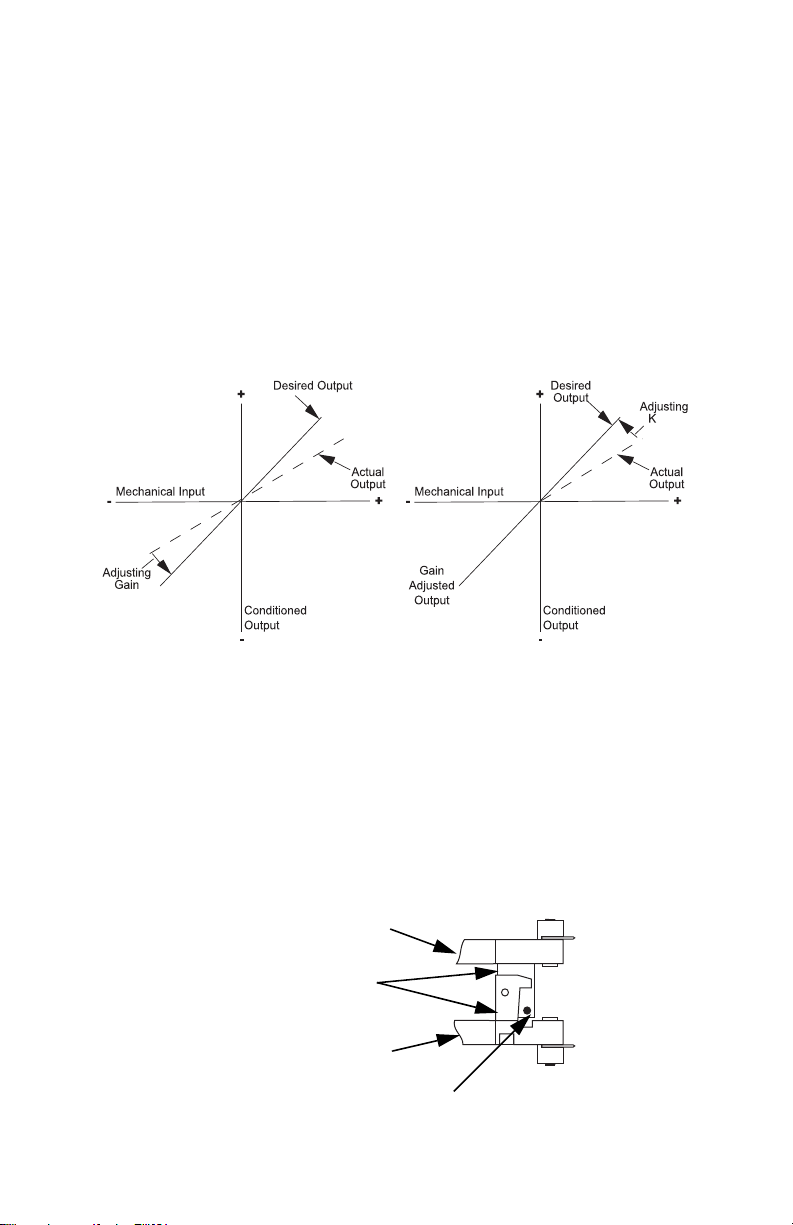
Gain
The conditioner is designed to have an output of approximately ±10 V at
the full-scale displacement of the desired range. Most transducers may
be used with this conditioner to obtain full-scale ranges down to 10% of
Calibration
41
Page 42

the full travel range of the transducer. (Full-scale ranges of 5% may be
Actual Displacement
Full-Scale Range
--------------------------------------------------
⎝⎠
⎛⎞
10 V× Calculated Output=
possible, but some increase in drift and noise will result.)
In most transducers, the best linearity is obtained by setting the gain
between 70% and 90% of the desired travel range instead of 100%. The
adjustment procedures in this manual use 80% full scale as the reference
value.
Delta K
Delta K is a feature of DC conditioners manufactured by MTS Systems
Corporation. Delta K compensates for differences in symmetry between
the positive and negative outputs of the transducer. Gain is usually
adjusted to calibrate the compression half of the transducer range. Use
Delta K to calibrate the tension half of the transducer range.
Symmetrical versus Asymmetrical Extensometers
Typical extensometers may have only positive output (tension only), or
may have both positive and negative output (tension and compression).
It is also possible that the extensometer has asymmetrical travel (such as
+10 mm and -2 mm). It is important that you determine the full scale
travel range of the extensometer before proceeding.
For example
Suppose you have an extensometer with an asymmetrical travel of +10
mm and -2 mm. It is desired to adjust the conditioner to have a full-scale
output equal to the full travel range of the extensometer. In this case +10
mm would approximately equal +10 V, and -2 mm would have an
output of -2 V. Gain would be adjusted so that -2mm would yield -2 V,
and delta K would be adjusted so that +8 mm would yield +8 V while
adjustments to zero are made to keep the null position of the
extensometer at zero.
In all cases, the actual displacement should be used to determine the
calculated output.
Note It may be difficult to obtain a displacement value of exactly 80%
full scale. In those cases, find a displacement you can achieve
42
Calibration
Page 43

and calculate the new conditioner output value for the
displacement. For example, suppose the calibration block is set
for 7.94 mm. Then your desired output would be 7.94 V.
The following table shows the proper conditioner output for each
extensometer displacement of the preceding example.
.
% F
ULL SCALE ACTUAL DISPLACEMENT OUTPUT
100% 10 mm +10 V
80% 8 mm +8 V
60% 6 mm +6 V
40% 4 mm +4 V
20% 2 mm +2 V
Zero 0 mm 0 V
-20% -2 mm -2 V
Adjust gain/ΔK for ±80% travel of a symmetrical extensometer.
Adjust gain for 80% or maximum negative travel (whichever is
greater) and ΔK for 80% of positive travel of an asymmetrical
extensometer.
How to Use a Vernier Caliper
This method requires a tool such as vernier caliper, micrometer, or other
precision measuring device. Use this procedure as a guideline to adjust
the gain for other sensors that can use the DC conditioner.
Note This is not the most accurate method, but may be used
depending upon your needs.
1. Set up the controller.
Your test controller must be configured to use the extensometer
signal.
A. Connect the extensometer to your controller.
B. Monitor the excitation voltage.
C. Monitor the extensometer signal.
Calibration
43
Page 44

D. Prepare to use the calibration controls on your controller.
True
Measurement
m
E. Adjust the excitation control to set the excitation to +6 V DC
or the voltage specified in the extensometer documentation.
2. Zero the conditioner output.
The arms of the extensometer must be in the zero reference
position. Depending on the extensometer, this can be accomplished
using the zero pin, stop block, or a special fixture.
Adjust the zero control to set the extensometer signal to 0.00 V
DC.
Note Several extensometers have asymmetrical outputs. This means
that the compression and tension outputs are not equal. Ensure
that you are aware of the maximum ratings of the extensometer
you are calibrating.
3. Adjust compression.
44
Because a true measurement is from the middle of each
extensometer arm, you must subtract the thickness of one of the
arms.
A. Remove the zero pin, fixture, or release the zero stop and
measure the extensometer arms as shown.
B. Adjust the caliper for a 80% compression displacement
(remember to subtract the thickness of one knife edge).
Calibration
Page 45

C. Adjust the gain control to set the extensometer signal to -8 V
True
Measurement
m
DC (or 80% of your calculated output).
4. Readjust the zero and compression.
Repeat Step 2 and Step 3 until the zero and gain outputs can be
measured without readjustment.
5. Adjust tension.
.
Calibration
Since a true measurement is from the middle of each extensometer
arm knife edge, you must add the thickness of one of the knife
edges.
A. Measure the extensometer arms as shown. You will need to
pinch the extensometer arms to contact the caliper.
B. Adjust the caliper for a 80% tension displacement (or the
maximum positive travel). Remember to add the thickness of
one arm.
C. Check the meter reading.
• If the extensometer signal is above +8 V DC (or 80% of your
calculated output), adjust delta K for an extensometer signal
of +8 V DC.
45
Page 46

• If the extensometer signal is below +8 V DC (or your
calculated output), the
the
ΔK adjustment to its original setting and use the gain
control to increase the voltage halfway from its present value
to +8 V DC (this splits the difference between compression
and tension).
How to Use a Calibration Block
MTS recommends using a calibration block to establish the initial gain
setting of the conditioner. The calibration block is a metal block with
grooves cut into it. The grooves allow you to adjust the gain for specific
displacements. The calibration block is usually provided by the
manufacturer of the extensometer. Use this procedure as a guideline to
calibrate other extensometers.
1. Set up the controller.
Your test controller must be configured to use the extensometer
signal.
A. Connect the extensometer to your controller.
B. Monitor the excitation voltage.
C. Monitor the extensometer signal.
ΔK adjustment cannot be made. Return
46
D. Prepare to use the calibration controls on your controller.
E. Adjust the excitation control to set the excitation to +6 V DC
or the voltage specified in the extensometer documentation.
2. Zero the conditioner output.
The arms of the extensometer must be in the zero reference
position. Depending on the extensometer, this can be accomplished
using the zero pin, stop block, or a special fixture.
Adjust the zero control to set the extensometer signal to 0.00 V
DC.
Note Several extensometers have asymmetrical outputs. This means
that the compression and tension outputs are not equal. Ensure
that you are aware of the maximum ratings of the extensometer
you are calibrating.
3. Adjust compression.
Calibration
Page 47

A. Remove the zero pin, fixture, or release the zero stop and
install the extensometer on the calibration block so that the
extensometer arms are in the grooves that represent about
80% compression displacement.
B. Adjust the gain control to set the extensometer signal to -8 V
DC (or 80% of your calculated output).
4. Readjust the zero and compression.
Repeat Step 2 and Step 3 until the zero and gain outputs can be
measured without readjustment.
5. Adjust tension.
Remove the extensometer from the calibration block and reinstall it
so arms of the extensometer are in the grooves that represent the
80% tension displacement (or the maximum positive travel).
• If the extensometer signal is above +8 V DC (or your
calculated output), adjust the
extensometer signal of +8 V DC.
• If the extensometer signal is below +8 V DC (or your
calculated output), the
the
ΔK adjustment to its original setting and use the gain
control to increase the voltage halfway from its present value
to +8 V DC (this splits the difference between compression
and tension).
ΔK (delta K) control for an
ΔK adjustment cannot be made. Return
How to Use a Calibration Stand
This method requires a tool such as the Model 650.03 Calibrator from
MTS Systems Corporation. Use this procedure as a guideline to
calibrate other extensometers.
1. Set up the controller.
Your test controller must be configured to use the extensometer
signal
Calibration
47
Page 48

.
m
A. Connect the extensometer to your controller.
B. Monitor the excitation voltage.
C. Monitor the extensometer signal.
D. Mount the extensometer onto the calibrator. Install it for the
zero position. Use the zero pin if it is available.
48
This figure shows a typical installation. Each extensometer
can use a variety of extensions, attachments, and other
mounting accessories.
E. Prepare to use the calibration controls on your controller.
F. Adjust the excitation control to set the excitation to +6 V DC
or the voltage specified in the extensometer documentation.
2. Zero the conditioner output.
The arms of the extensometer must be in the zero reference
position. Depending on the extensometer, this can be accomplished
using the zero pin, stop block, or a special fixture.
Adjust the zero control to set the extensometer signal to 0.00 V
DC.
Note Several extensometers have asymmetrical outputs. This means
that the compression and tension outputs are not equal. Ensure
that you are aware of the maximum ratings of the extensometer
you are calibrating.
Calibration
Page 49

3. Adjust compression.
A. Remove the zero pin, fixture, or release the zero stop.
B. Adjust the calibrator between zero and 100% compression of
the extensometer's full-scale range three times. This exercises
the extensometer to remove any hysteresis.
C. Adjust the calibrator for the 80% compression setting (or the
range being calibrated) and note the voltmeter reading.
• If the meter reading is less than -8 V DC you can adjust gain.
Adjust the gain control to set the extensometer signal to
-8 V DC (or 80% of your calculated output).
• If you cannot adjust the gain control to set the extensometer
signal to -8 V DC, you can change the excitation voltage.
4. Readjust the zero and compression.
Repeat Step 2 and Step 3 until the zero and gain outputs can be
measured without readjustment.
5. Adjust tension.
A. Adjust the calibrator between zero and 100% tension of the
extensometer’s full-scale range three times. This exercises the
extensometer to remove any hysteresis.
Calibration
B. Adjust the calibrator for 80% tension (or for the maximum
positive travel) of the range you are calibrating. Note the
meter reading.
• If the extensometer signal is above +8 V DC (or your
calculated output), adjust the
ΔK (delta K) control for an
extensometer signal of +8 V DC.
• If the extensometer signal is below +8 V DC (or your
calculated output), the
the
ΔK adjustment to its original setting and use the gain
ΔK adjustment cannot be made. Return
control to increase the voltage halfway from its present value
to +8 V DC (this splits the difference between compression
and tension).
49
Page 50

50
Calibration
Page 51

Installation
WARNING
This section describes how to mount the extensometer to a specimen
and zero the extensometer output.
Contents
How to Mount an Extensometer 52
About Quick Attachment Springs 53
About Metal Extension Springs 57
About Elastic Bands 60
Handling the extensometer while it is selected as the active control
mode can cause the actuator to move unpredictably.
Unpredictable actuator movement can cause personnel injury or
damage to the test equipment.
Ensure that the extensometer is not active when installing it to a
specimen.
The shield of the Extensometer (pin E for PT style connector and pin A
for Amphenol style connector) must be connected to the controllers
chassis ground. This is typically accomplished by using a metal or
metalized plastic connector and a braided shielded cable from the
controller to the Extensometer cable, see MTS cable part numbers 50120-0xx PT style or 56-233-6xx Amphenol style for an example.
Zero Extensometer Output
The purpose of zeroing the extensometer output is to identify the
starting position of the extensometer to the system controller. An
extensometer usually needs to be zeroed (at least checked) after it has
been installed.
For example, suppose the extensometer is installed and is a bit off from
its calibrated zero position. The controller can be programmed to accept
the current output from the extensometer as the zero output.
Installation
51
Page 52

See your controller manual for information on establishing the
extensometer zero output signal. The electrical output of the
extensometer is adjusted so that zero strain equals zero volts output.
Depending on the extensometer, the zero reference can be accomplished
using the zero pin, stop block, or a special fixture.
• Some extensometers includes a zero pin that can be inserted
into a zero reference hole. This locks the extensometer arms in
the zero reference position. This is useful for specimen
installation.
• Some extensometers have a zero stop built into the arms of the
extensometer. A zero stop works like an overtravel block.
When installing a specimen, pinch the two arms of the
extensometer together. This stops the extensometer’s arms in
the zero position.
• Some extensometers require special fixtures that set the arms
of the extensometer into the proper zero reference position.
How to Mount an Extensometer
Axial extensometers can be installed using quick attachment springs,
extension springs, or elastic bands.
• There are two types of quick attachment springs: a sliding spring
• Extension springs and elastic bands mount the extensometer to a
Prerequisites
The extensometer must be configured with the appropriate attachments
for the specimen and test.
The extensometer must also be calibrated for use. Every range defined
for the extensometer should be calibrated.
Procedure
When installing an axial extensometer on a specimen, the arms of the
extensometer must be in the zero reference position.
52
and an anchored spring.
specimen in the same way.
Installation
Page 53

1. Zero the arms of the extensometer. Depending on the extensometer,
this can be accomplished using the zero pin, stop block, or a special
fixture.
2. Hold the extensometer so that its knife edges contact the specimen.
3. Secure the upper arm around of the extensometer the specimen.
• If you are using an anchored spring mount, clip the spring
around the specimen. If you need to change the anchor
position, see the appropriate procedure.
• If you are using a sliding spring mount, see the appropriate
procedure.
• If you are using extension springs, connect one end of the
extension spring to the hook attachment of the upper arm. Use
the small utility hook to grab the other spring and pull it
around the specimen to the other attachment hook.
• If you are using an elastic band, connect one end of the elastic
band to the hook attachment for the upper arm. Use the small
utility hook to grab the other elastic band and pull it around
the specimen to the other attachment hook.
4. Repeat Step 3 for the lower arm of the extensometer.
5. Zero the extensometer’s output.
A. Remove the zero pin, fixture, or release the zero stop.
B. Check the extensometer output at your controller.
C. If necessary, zero the extensometer output at your controller.
About Quick Attachment Springs
Quick attachment springs hold the extensometer onto the specimen with
a pair of special springs that clip around the specimen (see the following
figure).
Each extensometer is provided with one spring set for round specimens
and two spring sets for flat specimens (one spring set with a short spring
length and one spring set with a long spring length).
Quick attachment springs can be adjusted to accommodate different
specimen thicknesses. They can be adjusted by sliding the spring in or
Installation
53
Page 54

out of the attachment adapter or by anchoring the spring in a different
e
e
hole on the attachment adapter.
Note If the specimen dimension is outside the range of the quick
attachment springs, other attachment methods must be used,
such as metal extension springs or elastic bands (an
assortment is provided with the extensometer), half disks, or
wireform springs.
A Variety of Quick Attachment Springs
Two types of springs
There are two types of quick attachment springs: sliding springs (the
upper examples in the preceding figure) and anchored springs (the lower
examples in the preceding figure). Sliding springs also accommodate
the specimen thickness along with adjusting the clamping pressure on
the specimen. Anchored springs have several preset holes to anchor the
spring to accommodate the specimen thickness.
How to Adjust the Sliding Spring Length
To mount an extensometer that has a sliding quick attach spring:
54
Installation
Page 55

1. The arms of the extensometer must be in the zero reference
CAUTION
Grasp the attachment
adapter with a small
adjustable wrench
when using the hex
wrench.
Spring
Locking
Screw
Hex Wrench
position. Depending on the extensometer, this can be accomplished
using the zero pin, stop block, or a special fixture.
The extensometer arms can be damaged when mishandled.
Excessive torque on the extensometer arms can damage the
extensometer.
Use an adjustable wrench to hold the extensometer arm or attachment
adapter. Loosen or tighten only those socket head cap screws on the
arm being held with the wrench. Do not hold the extensometer case
when loosening or tightening the socket head cap screws.
2. Using a small adjustable wrench, grasp the sides of one attachment
adapter.
.
Installation
3. While securely holding the attachment adapter, loosen the spring
locking screw on that attachment adapter with a hex wrench.
4. Repeat Step 2 and Step 3 to loosen the spring locking screw on the
other attachment adapter.
5. While measuring the wire end length, slide the spring in or out as
required for the specimen diameter or thickness.
55
Page 56

6. Ensure that the plane of the spring end is perpendicular to the side
Wire End
Length
Specimen
Dimension
Quick
Attactment
Springs
Parallel
Spring
Locking
Screws
90
o
of the extensometer.
7. While securely holding the attachment adapter with the adjustable
wrench, tighten the spring locking screw on that attachment
adapter.
8. Repeat Steps 1–6 for the other spring.
9. Check to ensure that both springs are parallel to each other and
perpendicular to the side of the extensometer.
How to Select an Anchor Position
56
You will need the installation drawing that came with the extensometer
for this procedure.
1. Separate the spring retainers from the springs by loosening (do not
remove) the socket head cap screws.
Installation
Page 57

2. Mount one spring in the appropriate hole in the attachment adapter
Spring
Spring
Retainer
Attachment
Adapter
l
MODEL
634.xx
l
MODEL
632.xx
as determined by the specimen dimensions (see the installation
drawing).
3. Slide the spring retainer over the end of the spring and tighten the
socket head cap screw. Orient the spring retainer in such a way that
it will not interfere with movement of the extensometer arm.
About Metal Extension Springs
Metal extension springs may be used for testing throughout the
temperature range of the extensometer. The metal extension springs are
stainless steel with an outside diameter of 3.18 mm (0.125 in). The
spring wire is 0.41 mm (0.016 in) thick. More than one spring can be
connected end-to-end to accommodate large specimens.
Spring length is selected based on specimen size and required contact
force. The recommended contact force is approximately 600 grams.
• Greater contact force will provide a more secure attachment under
conditions where slippage may occur such as operating at high
cyclic frequencies. The knife edges can damage the specimen at
high contact forces.
• Less contact force will reduce the possibility of damage to soft
specimens; however, the possibility of slippage increases.
Round specimens
Installation
An extension spring attachment method can be used for large and small
diameter round specimens. It can be used by all axial extensometers.
57
Page 58

Flat specimens
Two springs can be used for
larger diameter specimens.
One spring can be used on
smaller diameter specimens.
The disk attachment is for
narrow, flat specimens.
The wireform attachment is
for wide, flat specimens.
An extensometer can be mounted to a flat specimen with extension
springs using a disk or wireform attachment. When using a wireform
attachment, it is necessary to replace the attachment adapters with knife
edge hold-downs.
Extension Spring Table
Use the following table to determine which extension spring to use for a
specific specimen diameter. Depending on the specimen diameter, you
can select between different spring lengths and specimen contact forces.
The table shows the recommended spring lengths for a specific
specimen diameter and the contact force on the specimen for each
spring length.
Note The recommended contact force is approximately 600 grams.
58
Installation
Page 59

S
Free Length Measurement
for Single Spring
Free Length Measurement
for Multiple Springs
PECIMEN
DIAMETER
(IN)
MM
S
PRING FREE LENGTH MM (IN)
12.7
(0.50)
15.9
(0.62)
19.0
(0.75)
22.2
(0.87)
25.4
(1.00)
28.6
(1.12)
31.8
(1.25)
34.9
(1.37)
38.1
(1.50)
2.0 (0.08) 340
3.0 (0.12) 670
4.0 (0.16) 950 440
5.0 (0.20) 660 300
6.0 (0.24) 840 480
7.0 (0.28) 1000 640 340
8.0 (0.32) 780 495
9.0 (0.35) 925 620 360
10.0 (0.39) 1080 750 500 315
11.0 (0.43) 880 620 470
12.0 (0.47) 1000 705 585 360
13.0 (0.51) 825 685 470
14.0 (0.55) 910 780 580 380
15.0 (0.59) 1000 865 670 510 415
16.0 (0.63) 950 760 620 505
17.0 (0.67) 1030 840 725 580
18.0 (0.71) 920 815 650
19.0 (0.75) 990 900 720
20.0 (0.79) 1035 960 800
CONTACT FORCE (GRAMS)
Installation
59
Page 60

About Elastic Bands
Elastic bands are commonly used for testing at near room temperature.
The contact force may be varied by the cross-section size of the elastic
band and its overall length. Elastic bands can be used by all axial
extensometers.
• Elastic bands (rubber bands) of the type provided with the
extensometer are available from stationery supply stores.
• Orthodontic elastic bands may also be used and are available from
medical supply houses.
Round specimens
An elastic band attachment method can be used with round specimens.
Each knife edge requires a band to secure it to the specimen.
Flat specimens
An extensometer can be mounted to a flat specimen with elastic bands
using a disk or wireform attachment. When using a wireform
attachment, it is necessary to replace the attachment adapters with knife
edge hold-downs.
60
Installation
Page 61

Contact force
The disk attachment is for
narrow, flat specimens.
The wireform attachment is
for wide, flat specimens.
Determining the specimen contact force when using elastic bands is
difficult.
• Greater contact force will provide a more secure attachment under
conditions where slippage may occur such as operating at high
cyclic frequencies. The knife edges can damage the specimen at
high contact forces.
• Less contact force will reduce the possibility of damage to soft
specimens; however, the possibility of slippage increases.
Installation
61
Page 62

62
Installation
Page 63

Page 64

m
MTS Systems Corporation
14000 Technology Drive
Eden Prairie, Minnesota 55344-2290 USA
Toll Free Phone: 800-328-2255
(within the U.S. or Canada)
Phone: 952-937-4000
(outside the U.S. or Canada)
Fax: 952-937-4515
E-mail: info@mts.com
Internet: www.mts.com
ISO 9001 Certified QMS
 Loading...