

Page 1

Manual Title
Additional Information
be certain.
AHX800 High Elongation Extensometer
Product Manual
100-231-450 A
Page 2

Copyright information © 2011 MTS Systems Corporation. All rights reserved.
Trademark information MTS is a registered trademarks and MTS Criterion and MTS Insight are
trademarks of MTS Systems Corporation within the United States. These
trademarks may be protected in other countries.
Proprietary information Teflon is a registered trademark of E. I. du Pont de Nemours and Company.
Software use and license is governed by MTS’ End User License Agreement
which defines all rights retained by MTS and granted to the End User. All
Software is proprietary, confidential, and owned by MTS Systems Corporation
and cannot be copied, reproduced, disassembled, decompiled, reverse
engineered, or distributed without express written consent of MTS.
Software validation and
verification
Publication information
MTS software is developed using established quality practices in accordance
with the requirements detailed in the ISO 9001 standards. Because MTSauthored software is delivered in binary format, it is not user accessible. This
software will not change over time. Many releases are written to be backwards
compatible, creating another form of verification.
The status and validity of MTS’ operating software is also checked during
system verification and routine calibration of MTS hardware. These controlled
calibration processes compare the final test results after statistical analysis
against the predicted response of the calibration standards. With these established
methods, MTS assures its customers that MTS products meet MTS’ exacting
quality standards when initially installed and will continue to perform as intended
over time.
MANUAL PART NUMBER PUBLICATION DATE
100-231-450 A January 2011
100-231-450 A
* Change to Gage Length.
*
May 3013
2
AHX800 High Elongation Extensometer Product Manual
Page 3

Contents
Introduction 5
Functional Description 6
Specifications 7
Installation 9
Unpacking the Extensometer 10
Installing the AHX800 onto an MTS Criterion Frame 11
Operation 15
Setting up a Test 16
Running a Test 18
Maintenance 19
Replacing Spare Parts 20
AHX800 High Elongation Extensometer Product Manual Contents
3
Page 4

Page 5

Introduction
Contents Functional Description 6
The AHX800 High Elongation Extensometer is designed for testing high
elongation applications of elastomer materials such as latex, silicone, rubber,
polyurethane, and other similar materials. It is ideally suited for testing dog-bone
elastomer specimens per ASTM D412 and ISO 37 specifications.
Specifications 7
AHX800 High Elongation Extensometer
AHX800 High Elongation Extensometer Product Manual Introduction
5
Page 6
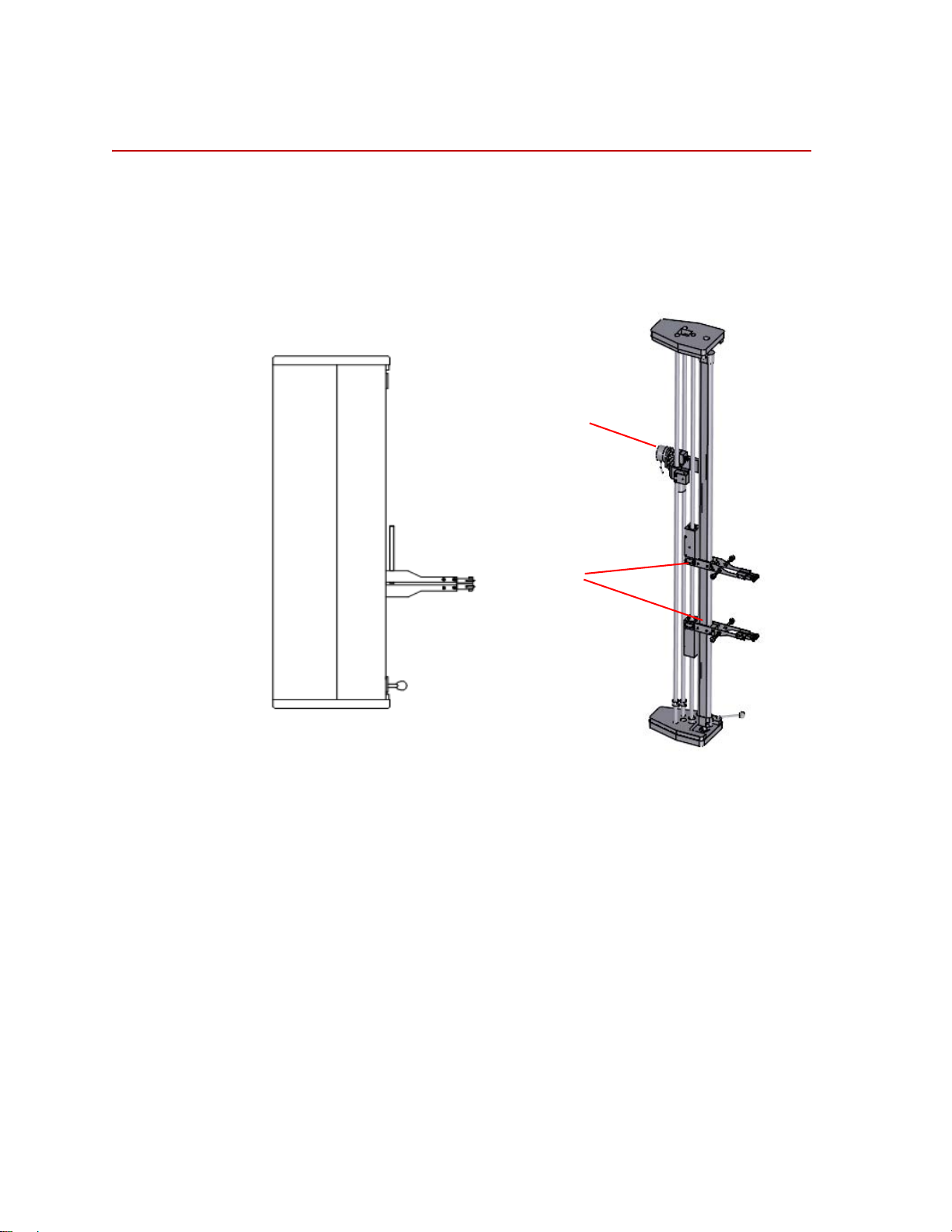
Functional Description
Arms
Optical Encoder
Functional Description
The AHX800 High Elongation Extensometer is designed to operate at
temperatures from 5 to 40°C. The key part of the extensometer is an optical
encoder. The movement of the extensometer arms makes the optical encoder
rotate. The encoder send pulses to a circuit where the pulses are converted for use
by the controller.
6
Introduction
Frame Assembly (all other component s)
The two arms of the extensometer are attached to the specimen. A cable/pulley
mechanism allows the arms to track the elongation of the specimen. The cable
movement is detected by an encoder. The encoder sends pulses to a circuit board
that converts the pulses to determine the exact displacement of the extensometer
arms.
The high elongation extensometer can rotate 90° to minimize the required
working space.
AHX800 High Elongation Extensometer Product Manual
Page 7

Specifications
PARAMETER SPECIFICATION
Usable travel 800 mm (31.5 in)
Specifications
Gage lengths
Measurement resolution 0.004 mm (0.00016 in)
Maximum arm opening 40 mm (1.57 in)
Knife edges Flat
Knife attachment method Adjustable mechanical spring
Weight Approximately 9.5 kg (20.9 lb)
Environmental For indoor use only
Temperature
Relative humidity 10 to 85%, noncondensing
Altitude For use at altitudes up to 2000 m (6500 ft)
Supply voltage + 5 V DC, 100 mA
10 - 125 mm (0.375 - 5 in)
Round
Rubber
Sharpened
5 to 40
°C
Conforms to European CE Directives
AHX800 High Elongation Extensometer Product Manual Introduction
7
Page 8
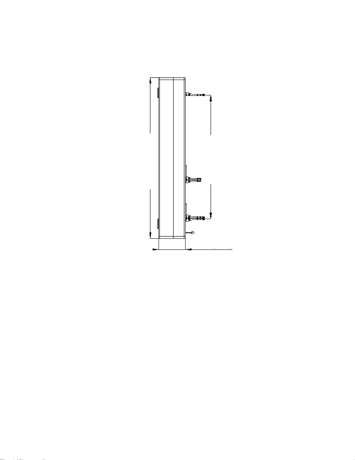
Specifications
1070 mm (42.1 in)
815 mm (32.1 in)
174 mm (6.9 in)
Dimensions
8
Introduction
AHX800 High Elongation Extensometer Product Manual
Page 9

Installation
WARNING
WARNING
Contents Unpacking the Extensometer 10
This section describes how to install the AHX800 High Elongation
Extensometer.
Installing the AHX800 onto an MTS Criterion Frame 11
The following hazards apply to all the installation procedures.
The extensometer electronics are sensitive to making electrical connections
with electrical power turned on.
Making electrical connections with power applied can cause damage to the
extensometer and/or other electronics.
Be sure electrical power is removed until instructed to turn it on.
Transporting the high
elongation
extensometer
Installation will require you to work with the extensometer.
The high elongation extensometer's arm and guide rod are easily damaged.
Handle the high elongation extensometer by its chassis.
Before transporting the high elongation extensometer, do the following:
• Use the two clamp screws to lock the arms in the bottom position.
• Set the L0 gage length stop in its lowermost position.
• Lock the carriage in its uppermost position with the screw in the red ring.
Do not forget to loosen the locking screws before attempting to use the high
elongation extensometer. See “Unpacking the Extensometer” on page 10.
AHX800 High Elongation Extensometer Product Manual Installation
9
Page 10

Unpacking the Extensometer
Collar Clamp
Collar Clamp
Unpacking the Extensometer
1. Unpack the high elongation extensometer and place it upright on a flat
surface.
2. Loosen the two locknuts on the right-side cover of the high elongation
extensometer, and then remove the right-side cover.
3. Unscrew the collar clamp on the bottom of the optical encoder assembly and
slide it to the bottom of the shaft.
4. Loosen the collar clamp on the top of the upper arm assembly , and slide it to
the top of the shaft and tighten in place. Loosen the collar clamp on the
bottom of the lower arm assembly and let it slide down to the bottom of the
shaft. The arms should freely slide from bottom to top.
10
Installation
AHX800 High Elongation Extensometer Product Manual
Page 11

Installing the AHX800 onto an MTS Criterion Frame
Lower Test Area Assembly Diagram
Round Axis
Inner Hexagon
Screw
Pin
Compression Spring
Cantilever
Hang Pin
Extensometer
Installing the AHX800 onto an MTS Criterion Frame
1. Lower Test Area Installation
A. The cantilever varies from different models; the basic shape is shown
as above.
B. Align the round axis and hang pin in the cantilever with the center hole
and the middle hole in the bottom plate of the extensometer.
C. Mount the extensometer to the cantilever and make them fit with each
other.
D. Rotate the extensometer; adjust the mounting angle of extensometer
and the frame.
E. Insert the pin, compression spring, and inner hexagon screw to lock the
cantilever and extensometer.
AHX800 High Elongation Extensometer Product Manual Installation
11
Page 12

Installing the AHX800 onto an MTS Criterion Frame
Upper Test Area Assembly Diagram
Round Axis
Cantilever
Extensometer
Hang Pin
Inner Hexagon
Screw
Pin
Compression
Spring
Top Plate
2. Upper Test Area Installation
A. The cantilever varies from different models; the basic shape is shown
as above.
B. Align the round axis and hang pin in the cantilever with the center hole
and the middle hole in the top plate of the extensometer.
C. Mount the extensometer to the cantilever; rotate the angle to make the
hang pin hitch the extensometer.
D. Adjust the mounting angle of the extensometer and frame.
E. Insert the pin, compression spring, and inner hexagon screw to lock the
extensometer and the cantilever.
12
Installation
AHX800 High Elongation Extensometer Product Manual
Page 13

Installing the AHX800 onto an MTS Criterion Frame
3. Connect the cable between the AHX800 board and the MTS Criterion
controller; one end of the cable is an RJ45 and the other end is a 15 pin D
connector.
AHX800 High Elongation Extensometer Product Manual Installation
13
Page 14

Page 15

Operation
Knife Edges
Upper Arm
Lower Arm
Adjustment
Rod Screw
Adjustment Rod
Knurled Knob
Contents Setting up a Test 16
This section describes how to use the AHX800 High Elongation Extensometer.
Running a Test 18
Component
identification
The following figure identifies the components referenced in the following
procedures.
AHX800 High Elongation Extensometer Product Manual Operation
15
Page 16

Setting up a Test
Knife Edges
Setting up a Test
To set up a test for a specimen:
1. Select a knife edge.
2. Adjust the gage length.
Choose a knife edge based on the type of specimen which will be tested.
The nature of the specimen material (surface quality, thickness, and so on.)
determines the type of knife edge to use.
The knife edges are secured with screws to the upper and lower arms.
A. Loosen the adjustment rod screw.
B. Place the appropriate wedge (desired gage length) between the knife
edges.
C. Gently press the knife edges together.
D. Tighten the adjustment rod screw.
16
Operation
3. Set the automatic return.
A. Set the arms in the desired position.
B. Loosen the locking screw on the finger holder (which is mounted to the
crosshead).
C. Adjust the crosshead so that the specimen grips are in the proper
position to hold a specimen.
D. Adjust the finger until it touches the upper arm.
E. Tighten the locking screw.
AHX800 High Elongation Extensometer Product Manual
Page 17

Setting up a Test
WARNING
4. Adjust the contact to the specimen.
The amount of clamping force on the specimen can be adjusted with the
knurled knobs of the upper and lower arm. This step must be done after the
specimen is installed. The clamping force should be adjusted when the
specimen type is changed.
Displacement limits on your test system can restrict the actuator movement
to a specified range.
Failure to establish upper and lower limits can damage the extensometer.
After adjusting the extensometer's contact with the specimen, you must adjust the
lower safety switch. The upper and lower switches control the crosshead
displacement at the end of a test according to the finger position.
AHX800 High Elongation Extensometer Product Manual Operation
17
Page 18

Running a Test
Arms Closed Arms Open
Running a Test
Before you start running a test, be sure to complete the procedures in “Setting Up
for a Test”.
1. Ensure the extensometer arms are open.
2. Insert a specimen into the grips.
3. Close the extensometer arms.
4. Perform the test.
5. When the test is complete, open the extensometer arms.
18
Operation
Note The crosshead return can be done with the arm open (the Teflon slide
reduces friction between the arms and the cam). In the case of intensive
testing, it is normal to see a thin layer (white) of Teflon on the cam.
AHX800 High Elongation Extensometer Product Manual
Page 19

Maintenance
This section describes how to maintain the AHX800 High Elongation
Extensometer. The serial number of the extensometer can be viewed at the base
of the right side of the high elongation extensometer chassis.
Routine maintenance Routine maintenance consists of visually inspecting the following:
• Check the surface quality of the knife edges.
• Remove dust and dirt from the assembly.
Cleaning the guide
column
T ake of f the left side of the assembly. Clean the guide column with a soft duster.
It is possible to use a soft tissue moistened with silicone oil to lubricate the guide
column (the silicone oil film should be very thin). Other solvent, cleaners, or
lubricants are not recommended (for example, grease or oil).
The guide column can be damaged when cleaned with cleaners or solvents
others than those recommended.
The use of cleaners, solvents, and other lubricants other than those
recommended can damage the components surface and increase the
friction of the mobile parts.
Use only silicone oil to lubricate the guide column.
AHX800 High Elongation Extensometer Product Manual Maintenance
19
Page 20

Replacing Spare Parts
Teflon Slide
Clamping
Force Spring
Leaf Arm
High Energy
Spring
Component Identification
Replacing Spare Parts
The topics on the following pages describe how to replace the spare parts. See the
following figure for component identification.
Knife
Knife edges 1. Remove the screw securing a knife edge.
2. Replace the old knife edge with a new one.
3. Secure the knife edge with the screw.
4. Repeat this procedure for all the knife edges.
Leaf arm 1. Remove the knurled knob.
2. Remove the screws securing the rear of the leaf arm.
3. Transfer the components from the old arm to the new one.
4. Loosely attach the leaf arm to the block, and screw the knurled knob back on.
5. Adjust the arm so that it is parallel with the other arms and tighten the screws.
Teflon slide 1. Remove the two screws securing the Teflon slide and replace it.
20
Maintenance
AHX800 High Elongation Extensometer Product Manual
Page 21

2. Tighten the two screws to secure the Teflon slide in place.
Clamping force spring 1. Unscrew the knurled knob until it is off the shaft.
2. Replace the old spring with the new one.
3. Screw the knurled knob back on the shaft.
High energy spring 1. Remove the screws holding the knife edge assembly.
2. Replace the spring (do not lose the small piston).
3. Install the new spring behind the small piston.
4. Install the knife edge assembly.
Replacing Spare Parts
AHX800 High Elongation Extensometer Product Manual Maintenance
21
Page 22

Page 23

Page 24

m
MTS Systems Corporation
http://www.mts.com/en/Global/index.asp
ISO 9001 Certified QMS
 Loading...