

Page 1

m
be certain.
Advantage™ Wedge Action Grips
Product Information
10 kN
30 kN
50 kN
100 kN
150 kN
300 kN
015-200-202 F
Page 2

Copyright information © 1997–2002, 2008 MTS Systems Corporation. All rights reserved.
Trademark information MTS and Advantage are registered trademarks of MTS Systems Corporation
within the United States. These trademarks may be protected in other countries.
Nikal is a registered trademark of DuPont Company.
Publication information
Manual Part Number Publication Date
152002-01A July 1997
152002-02A July 1998
015-200-202 B April 1999
015-200-202 C December 2000
015-200-202 D August 2001
015-200-202 E October 2002
015-200-202 F March 2008
2
Manual Template 4.3
Page 3

Contents
Technical Support 5
How to Get Technical Support 5
Before You Contact MTS 5
If You Contact MTS by Phone 7
Problem Submittal Form in MTS Manuals 8
Preface 9
Before You Begin 9
Conventions 10
Documentation Conventions 10
Introduction 13
MTS Advantage Wedge Action Grip Functional Description 15
Grip Environment 16
MTS Advantage Wedge Action Grips Specifications 17
MTS Advantage Wedge Action Grips Dimensions 18
MTS Advantage Wedge Action Grips—Flat Specimen Wedges 19
MTS Advantage Wedge Action Grips—Round Specimen Wedges 20
Safety Information 21
Hazard Placard Placement 21
MTS Advantage™ Wedge Action Grips
3
Page 4

Installation 23
About Grip Installation 23
Install the Grips 24
Operation 25
Changing Wedges 25
Installing a Specimen 27
Maintenance 31
4
MTS Advantage™ Wedge Action Grips
Page 5

Technical Support
How to Get Technical Support
Start with your
manuals
Technical support
methods
MTS web site
www.mts.com
E-mail techsupport@mts.com
Telephone MTS Call Center 800-328-2255
Fax 952-937-4515
The manuals supplied by MTS provide most of the information you need to use
and maintain your equipment. If your equipment includes MTS software, look
for online help and README files that contain additional product information.
If you cannot find answers to your technical questions from these sources, you
can use the internet, e-mail, telephone, or fax to contact MTS for assistance.
MTS provides a full range of support services after your system is installed. If
you have any questions about a system or product, contact MTS in one of the
following ways.
The MTS web site gives you access to our technical support staff by means of a
Technical Support link:
www.mts.com > Contact Us > Service & Technical Support
Weekdays 7:00 A.M. to 5:00 P.M., Central Time
Please include “Technical Support” in the subject line.
Before You Contact MTS
MTS can help you more efficiently if you have the following information
available when you contact us for support.
Know your site
number and system
number
Manual Name Technical Support
The site number contains your company number and identifies your equipmen t
type (material testing, simulation, and so forth). The number is usually written on
a label on your MTS equipment before the system leaves MTS. If you do not
have or do not know your MTS site number, contact your MTS sales engineer.
Example site number: 571167
5
Page 6

When you have more than one MTS system, the system job number identifies
which system you are calling about. You can find your job number in the papers
sent to you when you ordered your system.
Example system number: US1.42460
Know information from
prior technical
If you have contacted MTS about this problem before, we can recall your file.
You will need to tell us the:
assistance
• MTS notification number
• Name of the person who helped you
Identify the problem Describe the problem you are experiencing and know the answers to the
following questions:
• How long and how often has the problem been occurring?
• Can you reproduce the problem?
• Were any hardware or software changes made to the system before the
problem started?
• What are the model numbers of the suspect equipment?
• What model controller are you using (if applicable)?
• What test configuration are you using?
Know relevant
computer information
If you are experiencing a computer problem, have the following information
available:
• Manufacturer’s name and model number
Technical Supp ort
6
• Operating software type and service patch information
• Amount of system memory
• Amount of free space on the hard drive in which the application resides
• Current status of hard-drive fragmentation
• Connection status to a corporate network
Manual Name
Page 7

Know relevant
For software application problems, have the following information available:
software information
• The software application’s name, version number, build number, and if
available, software patch number. This information is displayed briefly
when you launch the application, and can typically be found in the “About”
selection in the “Help” menu.
• It is also helpful if the names of other non-MTS applications that are
running on your computer, such as anti-virus software, screen savers,
keyboard enhancers, print spoolers, and so forth are known and available.
If You Contact MTS by Phone
Your call will be registered by a Call Center agent if you are calling within the
United States or Canada. Before connecting you with a technical support
specialist, the agent will ask you for your site number, name, company , company
address, and the phone number where you can normally be reached.
If you are calling about an issue that has already been assigned a notification
number, please provide that number. You will be assigned a unique notification
number about any new issue.
Identify system type To assist the Call Center agent with connecting you to the most qualified
technical support specialist available, identify your system as one of the
following types:
• Electromechanical materials test system
• Hydromechanical materials test system
• Vehicle test system
• Vehicle component test system
• Aero test system
Be prepared to
Prepare yourself for troubleshooting while on the phone:
troubleshoot
• Call from a telephone when you are close to the system so that you can try
implementing suggestions made over the phone.
• Have the original operating and application software media available.
• If you are not familiar with all aspects of the equipment operation, have an
experienced user nearby to assist you.
Manual Name Technical Support
7
Page 8

Write down relevant
Prepare yourself in case we need to call you back:
information
• Remember to ask for the notification number.
• Record the name of the person who helped you.
• Write down any specific instructions to be followed, such as data recording
or performance monitoring.
After you call MTS logs and tracks all calls to ensure that you receive assistance and that action
is taken regarding your problem or request. If you have questions about the status
of your problem or have additional information to report, please contact MTS
again and provide your original notification number.
Problem Submittal Form in MTS Manuals
Use the Problem Submittal Form to communicate problems you are experiencing
with your MTS software, hardware, manuals, or service which have not been
resolved to your satisfaction through the technical support process. This form
includes check boxes that allow you to indicate the urgency of your problem and
your expectation of an acceptable response time. We guarantee a timely
response—your feedback is important to us.
The Problem Submittal Form can be accessed:
Technical Supp ort
8
• In the back of many MTS manuals (postage paid form to be mailed to MTS)
• www.mts.com > Contact Us > Problem Submittal Form (electronic form to
be e-mailed to MTS)
Manual Name
Page 9

Preface
Before You Begin
Safety first! Before you attempt to use your MTS product or system, read and understand the
Safety manual and any other safety information provided with your system.
Improper installation, operation, or maintenance of MTS equipment in your test
facility can result in hazardous conditions that can cause severe personal injury or
death and damage to your equipment and specimen. Again, read and understand
the safety information provided with your system before you continue. It is very
important that you remain aware of hazards that apply to your system.
Other MTS manuals In addition to this manual, you may receive additional MTS manuals in paper or
electronic form.
If you have purchased a test system, it may include an MTS System
Documentation CD. This CD contains an electronic copy of the MTS manuals
that pertain to your test system, including hydraulic and mechanical component
manuals, assembly drawings and parts lists, and op eration and preventive
maintenance manuals. Controller and application software manuals are typically
included on the software CD distribution disc(s).
Manual Name Preface
9
Page 10

Conventions
DANGER
WARNING
CAUTION
Conventions
Documentation Conventions
The following paragraphs describe some of the conventions that are used in your
MTS manuals.
Hazard conventions As necessary, hazard notices may be embedded in this manual. These notices
contain safety information that is specific to the task to be performed. Hazard
notices immediately precede the step or procedure that may lead to an associated
hazard. Read all hazard notices carefully and follow the directions that are given.
Three different levels of hazard notices may appear in your manuals. Following
are examples of all three levels.
Note For general safety information, see the safety information provided with
your system.
Danger notices indicate the presence of a hazard with a high level of risk which,
if ignored, will result in death, severe personal injury, or substantial property
damage.
10
Warning notices indicate the presence of a hazard with a medium level of risk
which, if ignored, can result in death, severe personal injury, or substantial
property damage.
Caution notices indicate the presence of a hazard with a low level of risk which,
if ignored, could cause moderate or minor personal injury, equipment damage, or
endanger test integrity.
Notes Notes provide additional information about operating your system or highlight
easily overlooked items. For example:
Note Resources that are put back on the hardware lists show up at the end of
the list.
Special terms The first occurrence of special terms is shown in italics.
Preface
Manual Name
Page 11

Conventions
Illustrations Illustrations appear in this manual to clarify text. It is important for you to be
aware that these illustrations are examples only and do not necessarily represent
your actual system configuration, test application, or software.
Electronic manual
conventions
This manual is available as an electronic document in the Portable Document
File (PDF) format. It can be viewed on any computer that has Adobe Acrobat
Reader installed.
Hypertext links The electronic document has many hypertext links displayed in a blue font. All
blue words in the body text, along with all contents entries and index page
numbers, are hypertext links. When you click a hypertext link, the application
jumps to the corresponding topic.
Manual Name Preface
11
Page 12

Conventions
12
Preface
Manual Name
Page 13

Introduction
Contents MTS Advantage Wedge Action Grip Functional Description 15
The MTS Advantage W edge Action Grips hold a test specimen in a load unit for
static tension testing. The grips can accommodate flat or round specimens.
Grip Environment 16
MTS Advantage Wedge Action Grips Specifications 17
MTS Advantage Wedge Action Grips Dimensions 18
MTS Advantage Wedge Action Grips—Flat Specimen Wedges 19
Manual Name Introduction
13
Page 14

MTS Advantage Wedge Action Grips—Round Specimen Wed ges 20
What you need to
Introduction
14
know
Mts Advantage Wedge Grips
MTS Systems Corporation assumes that you know how to use your controller.
See the appropriate manual for information about performing any controllerrelated step in this manual’s procedures. You are expected to know how to:
• Turn on power (electrical or hydraulic) to the load frame
(electromechanical) or load unit (servohydraulic).
• Adjust the crosshead and/or actuator position.
Manual Name
Page 15
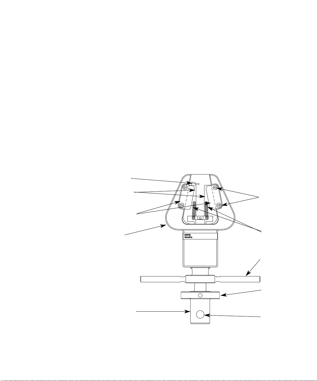
MTS Advantage Wedge Action Grip Functional Description
Retaining
Guides
Specimen
Guide
Grip
Body
Wedges
Retaining
Guide
Screws
Wedge
Springs
Grip
Handle
Locking
Collar
Mounting
Pin
Hole for
Mounting
Dowel
The MTS Advantage Wedge Action Grips are designed for static tension testing.
The grips are mounted in a load frame (also called a load unit) by attaching the
male mounting pin to a female mounting adapter and securing them with a
mounting dowel. A specimen can be installed either from the side of the grip or
from the top of the grip.
The grip handles are turned to apply an initial gripping force. The design of the
grips holds the wedges stationary while the specimen is being clamped. Once the
specimen is secured into both grips, a tensile load is applied to the specimen by
the test system. The tensile load pulls the specimen and wedges tighter into the
angled grip body, which increases the gripping force to prevent specimen
slippage during testing.
Two types of wedges are available for use with these grips: flat wedges for use
with flat specimens and vee-notched wedges for use with round specimens. Both
flat and vee-notched wedges are finished with a serrated texture to increase
gripping force.
Manual Name Introduction
15
Page 16
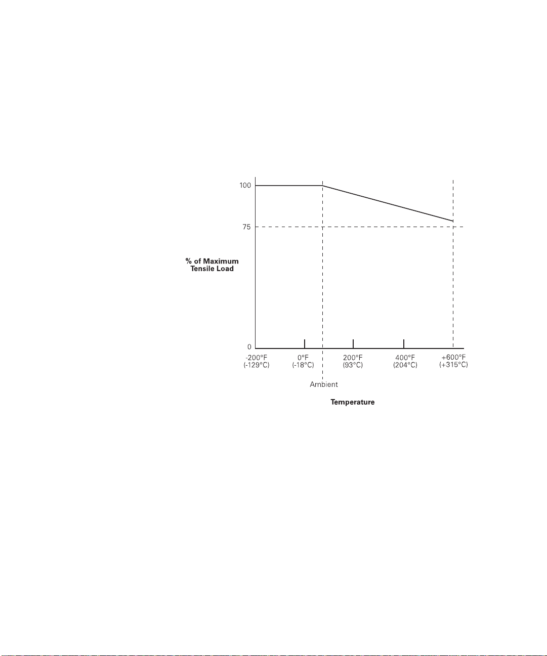
Grip Environment
The grips can be used at temperatures from -129 °C to +315 °C
(-200 °F to +600 °F). For testing at temperatures other than ambient conditions,
the grips can be mounted inside an environmental chamber. When using the grips
above ambient temperatures, the maximum tensile load must be reduced
according to the figure below. Also, if the grips are being used above +260 °C
(+500 °F), the stainless steel springs should be removed or they might have to be
replaced periodically.
16
Introduction
Manual Name
Page 17

MTS Advantage Wedge Action Grips Specifications
Grip Ratings
ODEL MONOTONIC TENSION CAPACITY WEIGHT (PER GRIP)MAXIMUM PRELOAD TORQUE
M
10 kN 10 kN (2 kip) 4.5 kg (10 lb) 11.3 N·m (100 in·lb)
30 kN 30 kN (6.7 kip) 5.5 kg (12 lb) 11.3 N·m (100 in·lb)
50 kN 50 kN (11 kip) 7 kg (15 lb) 15 N·m (130 in·lb)
100 kN 100 kN (22 kip) 15 kg (33 lb) 45 N·m (450 in·lb)
150 kN 150 kN (33 kip) 19.6 kg (43 lb) 68 N·m (600 in·lb)
300 kN 300 kN (67 kip) 53.5 kg (118 lb) 90 N·m (800 in·lb)
Specimen installation Some of the grips have a closed back which requires specimens to be installed
from the front of the grips. Some grips have an open back which allows
specimens to be installed from the front or the back of the grip.
Specimen Installation Access Locations
ODEL INSTALLATION
M
10 kN
30 kN
50 kN
100 kN
150 kN
300 kN
Manual Name Introduction
Front and Back
Front Only
Front Only
Front Only
Front Only
Front and Back
17
Page 18
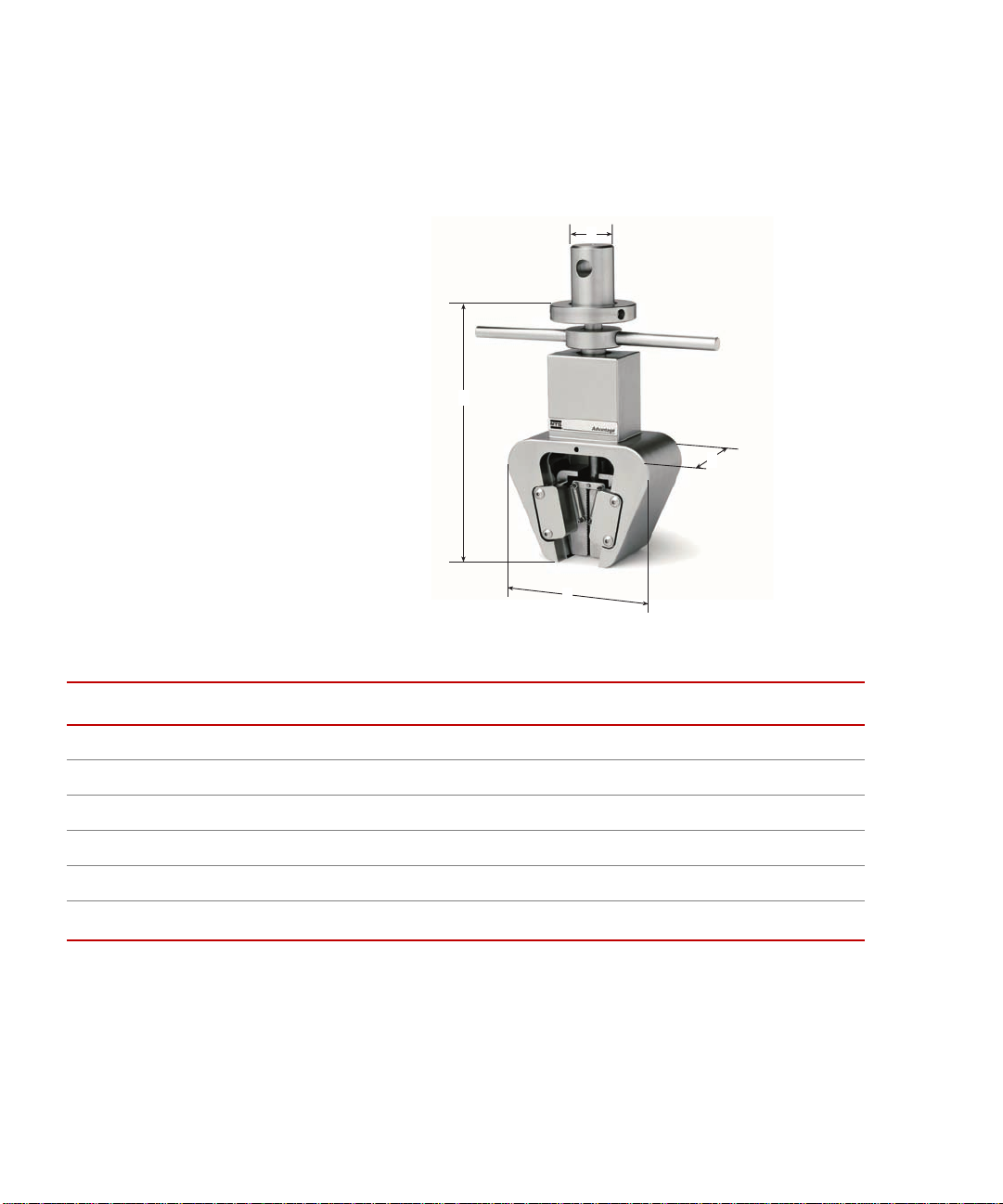
MTS Advantage Wedge Action Grips Dimensions
AA
BB
CC
DD
The dimensions shown in the figure correspond with the grip dimensions in the
following table.
Grip Dimensions
ODEL A B C
M
10 kN 172 mm (6.8 in) 132 mm (5.2 in) 62 mm (2.4 in) 1-1/4 in
30 kN 206 mm (8.1 in) 114 mm (4.4 in) 64 mm (2.5 in) 1-1/4 in
50 kN 210 mm (8.3 in) 147 mm (5.8 in) 63 mm (2.4 in) 1-1/4 in
100 kN 215 mm (8.5 in) 192 mm (7.5 in) 93 mm (3.7 in) 1-1/4 in
150 kN 259 mm (10.2 in) 193 mm (7.6 in) 102 mm (4.0 in) 1-1/4 in
300 kN 326 mm (12.8 in) 407 mm (16 in) 102 mm (4.0 in)
* 30 mm and 45 mm pin sizes are available upon request.
† Threaded stud M36 X 2 mm (1-1/2 in 12 UNC).
18
Introduction
*
D
†
Manual Name
Page 19

MTS Advantage Wedge Action Grips—Flat Specimen Wedges
T
Flat Specimen
The flat wedges are available for two force ranges.
10 kN to 50 kN (6 kip to 11 kip) Flat Specimen Wedges
PECIMEN THICKNESS (T) WEDGE WIDTH WEDGE SET
S
MM IN MM IN
0.0 to 7.9 0.00 to 0.31 25.4 1.00 053 140 801
4.06 to 10.92 0.23 to 0.52 25.4 1.00 053 140 802
* The wedge set assembly consists of a matched set of four wedges.
PART NUMBER
*
100 kN to 300 kN (22 kip to 67 kip) Flat Specimen Wedges
PECIMEN THICKNESS (T) WEDGE WIDTH WEDGE SET
S
MM IN MM IN
0.0 to 9.0 0.00 to 0.35 50.8 2.00 053 537 401
6.4 to 16 0.25 to 0.63 50.8 2.00 053 537 402
* The wedge set assembly consists of a matched set of four wedges.
Manual Name Introduction
PART NUMBER
*
19
Page 20

MTS Advantage Wedge Action Grips—Round Specimen Wedges
Round Specimen
D
The vee-notched wedges for round specimens are available for two force ranges.
10 kN to 50 kN (6 kip to 11 kip) Vee-Notched Wedges
PECIMEN DIAMETER (D) WEDGE SET
S
MM IN
PART NUMBER
*
3.0 to 7.9 Side Installation
3.0 to 7.9 Top Installation
7.0 to 9.5 Side Installation
7.0 to 12.7 Top Installation
11.5 to 12.7 Side Installation
11.5 to 16.0 Top Installation
* The wedge set assembly consists of a matched set of four wedges.
0.12 to 0.31 Side Installation
0.12 to 0.31 Top Installation
0.27 to 0.37 Side Installation
0.27 to 0.50 Top Installation
0.45 to 0.50 Side Installation
0.45 to 0.63 Top Installation
053-140-803
053-140-804
053-537-805
100 kN to 300 kN (22 kip to 67 kip) Vee-Notched Wedges
PECIMEN DIAMETER (D) WEDGE SET
S
MM IN
3.2 to 5.8 Side Installation
3.2to 7.6 Top Installation
5 to 10.4 Side Installation
5 to 12.5 Top Installation
12.2 to 15.5 Side Installation
12.2 to 19.5 Top Installation
* The wedge set assembly consists of a matched set of four wedges.
0.12 to 0.23 Side Installation
0.12 to 0.30 Top Installation
0.19 to 0.41 Side Installation
0.19 to 0.49 Top Installation
0.48 to 0.61 Side Installation
0.48 to 0.76 Top Installation
PART NUMBER
053-537-405
053-537-403
053-537-404
*
Introduction
20
Manual Name
Page 21

Safety Information
Hazard Placard Placement
Hazard placards contain specific safety information and are affixed directly to the
system so they are plainly visible.
Each placard describes a system-related hazard. When possible, international
symbols (icons) are used to graphically indicate the type of hazard and the
placard label indicates its severity. In some instances, the placard may contain
text that describes the hazard, the potential result if the hazard is ignored, and
general instructions about how to avoid the hazard.
The following label is typically located on the grip.
ABEL DESCRIPTION
L
Grip ID Plate.
Contains the following information:
• Model number
• Load rating
• Temperature range
Manual Name Safety Information
21
Page 22

Safety Information
22
Manual Name
Page 23
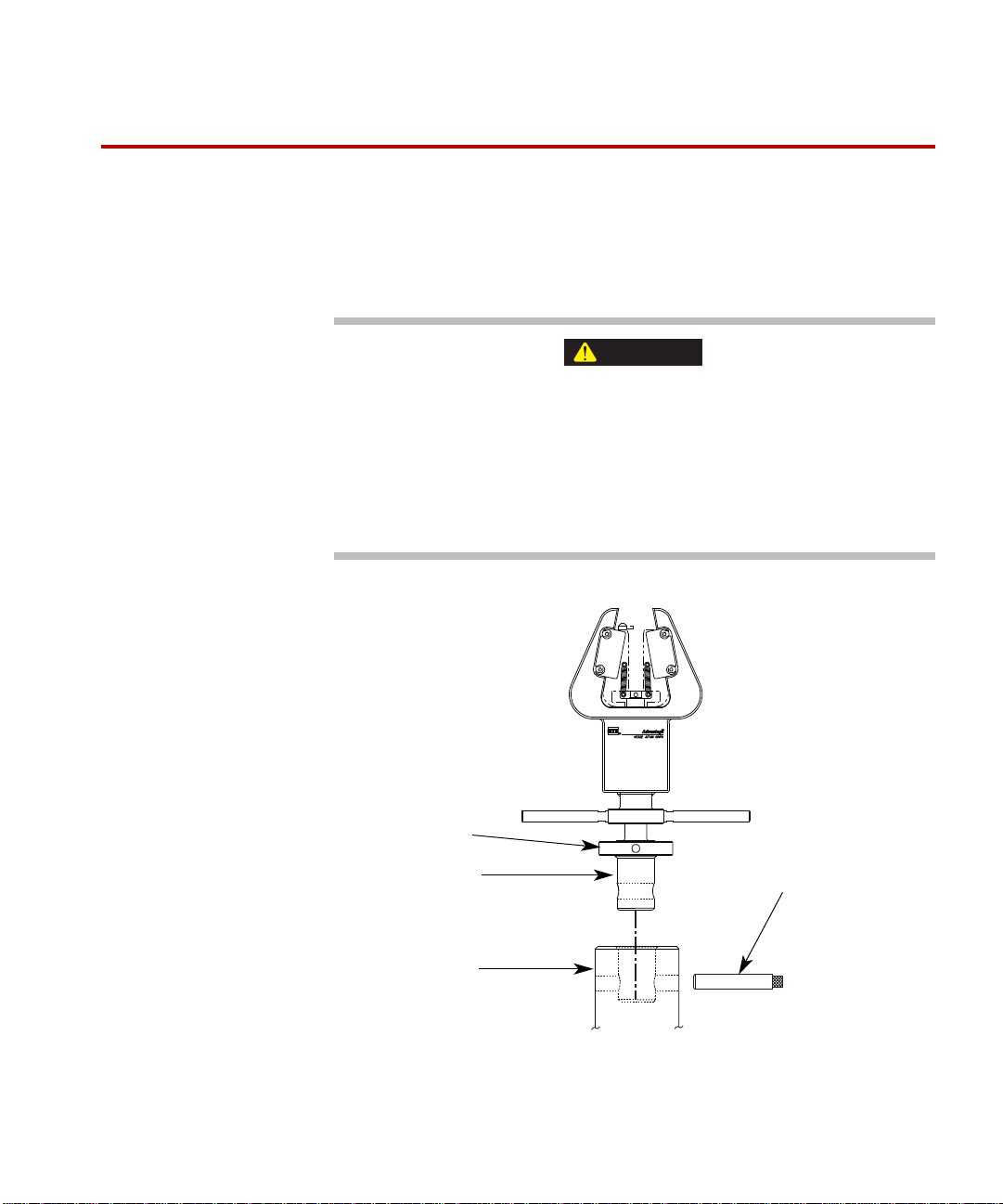
Installation
WARNING
Locking
Collar
Mounting
Pin
Mounting
Dowel
Load Frame
Mounting
Adapter
About Grip Installation
This section describes how to install the MTS Advantage Wedge Grips in a load
frame.
Grip Installation is inherently dangerous because it occurs within the crush
zone of the force train. During installation (electrical or servohydraulic)
power is applied to the system because crosshead or actuator movement is
required.
Serious injury and damage to the equipment can occur.
Take every precaution to avoid unexpected crosshead or actuator movement.
Manual Name Installation
Installation Components
23
Page 24

Servohydraulic
adapter
Install the Grips
If you are installing the grips on a servohydraulic load unit, you must install a
load unit mounting adapter on the actuator and on the force transducer.
Servohydraulic installations require the attachment kit (MTS part number 051880-3xx) for the appropriate parts.
1. Turn on the power to the load frame.
2. Adjust the crosshead position as necessary to allow adequate room to install
the grips.
3. Turn the load frame power off.
24
Installation
4. Clean all of the surfaces that will contact each other (such as the mounting
pin and the load frame mounting adapter) and lubricate them with Nikal.
5. Install the grips.
Install the mounting pin into the load frame mounting adapter. Align the
holes of the mounting pin with the load frame mounting adapter and install
the mounting dowel to attach the grip assembly to the load frame. Repeat
this step for the other grip.
Note The 300 kN grip does not use a mounting pin or load frame mounting
adapter. It is threaded into the load frame.
6. When both grips are mounted to the load frame, align the upper and lower
grips to each other and tighten the locking collars to preload the connection.
7. Install the wedges.
Manual Name
Page 25

Operation
Retaining
Guides
Specimen
Guide
Wedges
Retaining
Guide
Screws
Wedge
Springs
Spring Anchor Post
(view rotated 90
°)
Spring
Retaining
Clip (2)
Contents Changing Wedges 25
Changing Wedges
This section describes how to operate the MTSAdv antage Wedge Action Grips.
Installing a Specimen 27
T wo standard types of wedges are available for the grips: flat wedges for flat
specimens and vee-notched wedges for round specimens. Perform the following
procedure to replace one type of wedge with the other.
Note Each wedge is labeled with the wedge part number and manufacturing
date code. Be sure that replacement wedges are a matched set before
attempting to install the wedges into the grip.
1. Remove any specimen installed in the grips. Position the actuator or
crosshead as necessary for convenient access to the grip wedges. If
applicable, remove system hydraulic pressure.
Manual Name Operation
25
Page 26

The wedge springs can become dislodged and fly out of the grip assembly.
WARNING
The wedge spring can attain a force that can hurt you.
Ensure that the retaining clip is installed on the spring anchor post.
2. The lower end of the wedge spring is secured to the spring post with a
retaining clip (star washer). If the retaining clip is not present, install one
before disconnecting the spring from the wedge. Disconnect the springs that
are attached to each wedge.
3. Remove the two screws securing the retaining guides and remove the
retaining guides.
4. Remove the wedges from the grip body.
5. Remove any debris from the grip body that might have collected during
testing.
6. Apply a thin coat of Nikal lubricant to the surfaces of the wedge that contact
the grip body.
7. Place the wedges in the grip body.
8. Replace the retaining guides so that the pin on the wedge is in the slot.
Secure with two screws.
Operation
26
9. Replace springs on each wedge.
Manual Name
Page 27
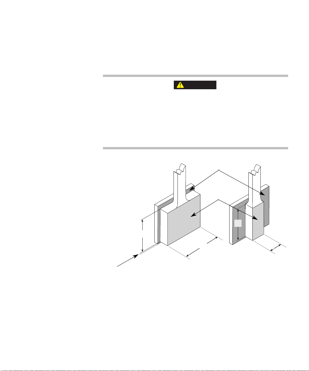
Installing a Specimen
CAUTION
W
W
H
H
Large contact area
recommended
Small contact area can
cause premature wear
and damage the grips
Wedge face
Contact area
Bottom gap
specification
(3-6 mm)
(H x W)
The following procedure describes how to install a specimen in the MTS
Advantage Wedge Grips. This procedure assumes a set of wedges has been
properly installed.
The contact area between the grip face and specimen should be as large as
possible.
A small contact area between the grip face and specimen can cause
premature wear to the grip face surface.
MTS recommends that specimens should be machined to provide the largest
possible surface contact area between the grip face and the specimen.
Manual Name Operation
27
Page 28

Improper specimen installation can damage the wedges.
CAUTION
6 mm (0.25 in) Maximum
6 mm (0.25 in) Maximum
Specimen
To prevent damage to the grips, follow the installation procedure. Do not install
specimens with hardness of Rc 52 or greater.
28
Operation
Specimen Installation
1. Apply power to the load frame or load unit.
Manual Name
Page 29
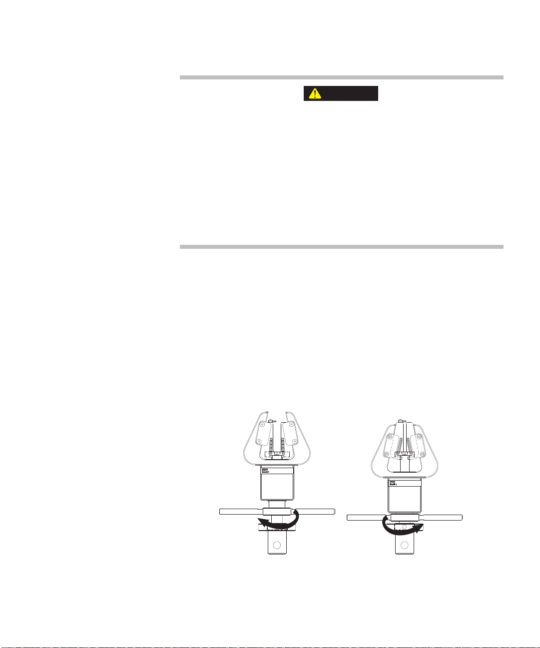
2. Open the upper and lower grips.
CAUTION
Grips Closed
Grips Open
Specimen slippage during the test can damage the grips.
Specimen slippage typically occurs when:
• Insufficient grip pressure is used to securely grip the specimen.
• Grip faces or wedges with rounded or flattened serrations are used.
• The specimen is harder than the wedge or face material.
Do not exceed the maximum pressure rating of the grip. Increasing the pressure
setting to hold round specimens can reduce the life of the vee-notched wedges.
Do not install specimens with hardness of Rc 52 or greater.
3. Place the specimen in the lower grip allowing a space of at least 3 mm (0.12
in), but not greater than 6 mm (0.25 in), between the bottom of the specimen
and the bottom inner edges of the lower grip wedges. Turn the grip handles
until specimen is firmly secured in place.
4. Lower the crosshead or extend the actuator until the specimen is positioned
in the upper grip allowing a space of at least 3 mm (0.12 in) but not greater
than 6 mm (0.25 in), between the top of the specimen and the inner top
edges of the wedges. Turn the grip handles until the specimen is firmly
secured in place.
Manual Name Operation
29
Page 30

30
Operation
Manual Name
Page 31

Maintenance
Service kits The following table lists the part numbers of the available service kits. The kits
After approximately 500 uses (or weekly, whichever comes first), the wedges of
the grip should be removed and an anti-seizing compound applied to the edges of
the wedge which contact the wedge chamber. The grip wedges should also be
lubricated if the grips have been in extended storage. Perform the following steps
to lubricate the wedges. Material required is Nikal lubricant (MTS part number
011-354-402).
1. Remove the wedges from the grip body.
2. Clean the grip assemblies to remove any dust or particales that might scatch
the grip surfaces or wedge faces.
3. Apply a thin layer of Nikal lubricant to the edges of the wedge which
contact the wedge chamber and grip piston.
4. Repeat Steps 1 and 2 for the other grip.
5. Place each wedge back into the grip body.
include components needed to replace the springs and restore the wedge action.
M
ODEL PART NUMBER
10 kN
30 kN
50 kN
100 kN
150 kN
300 kN
Manual Name Maintenance
560116-01
560116-01
560116-01
560116-02
560116-02
560116-02
31
Page 32

32
Maintenance
Manual Name
Page 33

Page 34

m
MTS Systems Corporation
14000 Technology Drive
Eden Prairie, Minnesota 55344-2290 USA
Toll Free Phone: 800-328-2255
(within the U.S. or Canada)
Phone: 952-937-4000
(outside the U.S. or Canada)
Fax: 952-937-4515
E-mail: info@mts.com
Internet: www.mts.com
ISO 9001 Certified QMS
 Loading...