

Page 1

m
be certain.
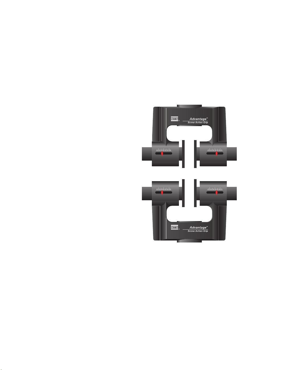
Advantage™ Screw Action Grip
Product Information
015-205-101 E
Page 2

Copyright information © 1999–2001, 2005, 2008 MTS Systems Corporation. All rights reserved.
Trademark information MTS is a registered trademark and of MTS Systems Corporation within the
United States. This trademark may be protected in other countries.
Advantage is a trademark of MTS Systems Corporation within the United States.
This trademark may be protected in other countries.
Molykote is a registered trademark of Dow Chemical Corporation.
Scotch-Brite is a trademark of 3M.
Publication information
Manual Part Number Publication Date
015-205-101 A April 1999
015-205-101 B August 2000
015-205-101 C January 2001
015-205-101 D February 2005
015-205-101 E March 2008
2
Manual Template 4.3
Page 3

Contents
Technical Support 5
How to Get Technical Support 5
Before You Contact MTS 5
If You Contact MTS by Phone 7
Problem Submittal Form in MTS Manuals 8
Preface 9
Before You Begin 9
Conventions 10
Documentation Conventions 10
Introduction 13
MTS Advantage Screw Action Grips Functional Description 13
MTS Advantage Screw Action Grips Specifications 15
Installation 17
Install Grips on Servohydraulic Systems 17
Install Grips on Electromechanical Systems 19
MTS Advantage™ Screw Action Grips
3
Page 4

Operation 21
About Selecting Face Surfaces 22
Grip Faces for 100 N (22.5 lbf) and 2000 N (450 lbf) Grips 23
Grip Faces for 5000 N (1124 lbf) Grips 26
Grip Faces for 10000 N (2250 lbf) Grips 27
How to Change Face Surfaces 28
How to Select Pucks 29
Puck Selection Guidelines 31
How to Change Pucks 36
How to Install a Specimen—Servohydraulic Systems 37
How to Install a Specimen—Electromechanical Systems 38
Maintenance 41
General Maintenance 41
MTS Advantage Screw Action Wedge Grip Service Kits 42
Advantage Screw Action Grips Replacement Parts 43
4
MTS Advantage™ Screw Action Grips
Page 5

Technical Support
How to Get Technical Support
Start with your
manuals
Technical support
methods
MTS web site
www.mts.com
E-mail techsupport@mts.com
Telephone MTS Call Center 800-328-2255
Fax 952-937-4515
The manuals supplied by MTS provide most of the information you need to
use and maintain your equipment. If your equipment includes MTS
software, look for online help and README files that contain additional
product information.
If you cannot find answers to your technical questions from these sources,
you can use the internet, e-mail, telephone, or fax to contact MTS for
assistance.
MTS provides a full range of support services after your system is installed.
If you have any questions about a system or product, contact MTS in one of
the following ways.
The MTS web site gives you access to our technical support staff by means
of a Technical Support link:
www.mts.com > Contact Us > Service & Technical Support
Weekdays 7:00 A.M. to 5:00 P.M., Central Time
Please include “Technical Support” in the subject line.
Before You Contact MTS
MTS can help you more efficiently if you have the following information
available when you contact us for support.
Know your site
number and system
number
MTS Advantage™ Screw Action Grips Technical Support
The site number contains your company number and identifies your
equipment type (material testing, simulation, and so forth). The number is
usually written on a label on your MTS equipment before the system leaves
MTS. If you do not have or do not know your MTS site number, contact your
MTS sales engineer.
5
Page 6

Example site number: 571167
When you have more than one MTS system, the system job number
identifies which system you are calling about. You can find your job number
in the papers sent to you when you ordered your system.
Example system number: US1.42460
Know information from
prior technical
If you have contacted MTS about this problem before, we can recall your
file. You will need to tell us the:
assistance
• MTS notification number
• Name of the person who helped you
Identify the problem Describe the problem you are experiencing and know the answers to the
following questions:
• How long and how often has the problem been occurring?
• Can you reproduce the problem?
• Were any hardware or software changes made to the system before the
problem started?
• What are the model numbers of the suspect equipment?
• What model controller are you using (if applicable)?
• What test configuration are you using?
Know relevant
computer information
If you are experiencing a computer problem, have the following information
available:
• Manufacturer’s name and model number
6
Technical Support
• Operating software type and service patch information
• Amount of system memory
• Amount of free space on the hard drive in which the application resides
• Current status of hard-drive fragmentation
• Connection status to a corporate network
MTS Advantage™ Screw Action Grips
Page 7

Know relevant
software information
For software application problems, have the following information
available:
• The software application’s name, version number, build number, and if
available, software patch number. This information is displayed briefly
when you launch the application, and can typically be found in the
“About” selection in the “Help” menu.
• It is also helpful if the names of other non-MTS applications that are
running on your computer, such as anti-virus software, screen savers,
keyboard enhancers, print spoolers, and so forth are known and
available.
If You Contact MTS by Phone
Your call will be registered by a Call Center agent if you are calling within
the United States or Canada. Before connecting you with a technical support
specialist, the agent will ask you for your site number, name, company,
company address, and the phone number where you can normally be
reached.
If you are calling about an issue that has already been assigned a notification
number, please provide that number. You will be assigned a unique
notification number about any new issue.
Identify system type To assist the Call Center agent with connecting you to the most qualified
technical support specialist available, identify your system as one of the
following types:
• Electromechanical materials test system
• Hydromechanical materials test system
• Vehicle test system
• Vehicle component test system
• Aero test system
Be prepared to
Prepare yourself for troubleshooting while on the phone:
troubleshoot
• Call from a telephone when you are close to the system so that you can
try implementing suggestions made over the phone.
• Have the original operating and application software media available.
MTS Advantage™ Screw Action Grips Technical Support
7
Page 8

• If you are not familiar with all aspects of the equipment operation, have
an experienced user nearby to assist you.
Write down relevant
Prepare yourself in case we need to call you back:
information
• Remember to ask for the notification number.
• Record the name of the person who helped you.
• Write down any specific instructions to be followed, such as data
recording or performance monitoring.
After you call MTS logs and tracks all calls to ensure that you receive assistance and that
action is taken regarding your problem or request. If you have questions
about the status of your problem or have additional information to report,
please contact MTS again and provide your original notification number.
Problem Submittal Form in MTS Manuals
Use the Problem Submittal Form to communicate problems you are
experiencing with your MTS software, hardware, manuals, or service which
have not been resolved to your satisfaction through the technical support
process. This form includes check boxes that allow you to indicate the
urgency of your problem and your expectation of an acceptable response
time. We guarantee a timely response—your feedback is important to us.
The Problem Submittal Form can be accessed:
8
Technical Support
• In the back of many MTS manuals (postage paid form to be mailed to
MTS)
• www.mts.com > Contact Us > Problem Submittal Form (electronic
form to be e-mailed to MTS)
MTS Advantage™ Screw Action Grips
Page 9

Preface
Before You Begin
Safety first! Before you attempt to use your MTS product or system, read and understand
the Safety manual and any other safety information provided with your
system. Improper installation, operation, or maintenance of MTS equipment
in your test facility can result in hazardous conditions that can cause severe
personal injury or death and damage to your equipment and specimen.
Again, read and understand the safety information provided with your
system before you continue. It is very important that you remain aware of
hazards that apply to your system.
Other MTS manuals In addition to this manual, you may receive additional MTS manuals in
paper or electronic form.
If you have purchased a test system, it may include an MTS System
Documentation CD. This CD contains an electronic copy of the MTS
manuals that pertain to your test system, including hydraulic and mechanical
component manuals, assembly drawings and parts lists, and operation and
preventive maintenance manuals. Controller and application software
manuals are typically included on the software CD distribution disc(s).
MTS Advantage™ Screw Action Grips Preface
9
Page 10

Conventions
DANGER
WARNING
CAUTION
Conventions
Documentation Conventions
The following paragraphs describe some of the conventions that are used in
your MTS manuals.
Hazard conventions As necessary, hazard notices may be embedded in this manual. These notices
contain safety information that is specific to the task to be performed.
Hazard notices immediately precede the step or procedure that may lead to
an associated hazard. Read all hazard notices carefully and follow the
directions that are given. Three different levels of hazard notices may appear
in your manuals. Following are examples of all three levels.
Note For general safety information, see the safety information provided
with your system.
Danger notices indicate the presence of a hazard with a high level of risk
which, if ignored, will result in death, severe personal injury, or substantial
property damage.
10
Warning notices indicate the presence of a hazard with a medium level of
risk which, if ignored, can result in death, severe personal injury, or
substantial property damage.
Caution notices indicate the presence of a hazard with a low level of risk
which, if ignored, could cause moderate or minor personal injury, equipment
damage, or endanger test integrity.
Notes Notes provide additional information about operating your system or
highlight easily overlooked items. For example:
Note Resources that are put back on the hardware lists show up at the
end of the list.
Special terms The first occurrence of special terms is shown in italics.
Preface
MTS Advantage™ Screw Action Grips
Page 11

Conventions
Illustrations Illustrations appear in this manual to clarify text. It is important for you to be
aware that these illustrations are examples only and do not necessarily
represent your actual system configuration, test application, or software.
Electronic manual
conventions
This manual is available as an electronic document in the Portable
Document File (PDF) format. It can be viewed on any computer that has
Adobe Acrobat Reader installed.
Hypertext links The electronic document has many hypertext links displayed in a blue font.
All blue words in the body text, along with all contents entries and index
page numbers, are hypertext links. When you click a hypertext link, the
application jumps to the corresponding topic.
MTS Advantage™ Screw Action Grips Preface
11
Page 12

Conventions
12
Preface
MTS Advantage™ Screw Action Grips
Page 13

Introduction
Contents MTS Advantage Screw Action Grips Functional Description 13
The MTS Advantage Screw Action Grips hold a test specimen in a load unit
for static tension testing. The grips can only accommodate flat-surfaced
specimens.
MTS Advantage Screw Action Grips Specifications 15
What you need to
know
MTS Systems Corporation assumes that you know how to use your
controller. See the appropriate manual for information about performing any
controller-related step in this manual’s procedure. You are expected to know
how to perform the following procedures:
• Turn hydraulic pressure on and off.
• Select a control mode.
• Manually adjust the actuator position.
• Install a specimen.
• Define a simple test.
• Run a test.
MTS Advantage Screw Action Grips Functional Description
The MTS Advantage Screw Action Grips are designed for static tension
testing. The grips are supplied with socket head cap screws for
servohydraulic load unit installations; optional pin adapters and other
mounting accessories are available for electromechanical test systems.
MTS Advantage™ Screw Action Grips Introduction
13
Page 14
The grips have serrated knobs that are used to manually apply an initial
gripping force on the specimen. For grips rated above 100 N (25 lbf), once
the specimen is hand tightened into the grips, a torque wrench is used to
ensure there is adequate clamping. The torque wrench also compresses a
compliant compression puck to ensure the face surfaces follow specimen
deformation during elongation. The tensile load pulls the face surfaces,
forcing them to pivot around a pin. The pivoting reduces the clamping
pressure at the top of the face surfaces and increases it at the bottom of the
face surfaces. Rotation of the face surfaces reduces the likelihood of a failure
in the high stress area of the clamp.
14
Introduction
MTS Advantage™ Screw Action Grips
Page 15

Grip faces Six types of face surfaces are available for use with these grips:
• Corrugated for gripping smooth specimens
• Serrated for gripping soft material
• Rubber coated for extra gripping protection for thin specimens
• Diamond tipped for more aggressive gripping needs
• Grab test for gripping fabric specimens
• Line contact for gripping rubber, latex, and cable sheath
MTS Advantage Screw Action Grips Specifications
The following tables list the specifications for the MTS Advantage Screw
Action Grips and for the specimens that are to be tested. Specifications are
defined at room temperature.
MONOTONIC TENSION CAPACITY RATING
M
ODEL
100 N 100 25
2000 N 2000 450
N LBF
5000 N 5000 1125
10,000 N 10,000 2250
MODEL SPECIMEN
T
HICKNESS
(
MAXIMUM)
MM IN MM IN MM IN KG LBS
100 N 12 0.50 78 3 100 3.9 0.36 0.80 055-426-701
2000 N 19 0.75 95 3.9 125 4.9 0.95 2.1 055-426-801
5000 N 25 1.00 123 4.8 170 6.7 2.1 4.6 055-426-901
10,000 N 25 1.00 123 4.8 170 6.7 4.9 10.8 100-030-185
MTS Advantage™ Screw Action Grips Introduction
RIP HEIGHT GRIP WIDTH
G
(DOES NOT INCLUDE
PISTON SCREW)
RIP WEIGHT PART NUMBER
G
15
Page 16

S
IZE
15 mm M6 x 1 055-425-901
30 mm M12 x 1.25 055-425-701
45 mm M12 x 1.25 055-426-001
5/8 in M6 x 1 055-425-801
1-1/4 in M6 x 1 100-021-398
1-1/4 in M12 x 1.25 055-425-601
* Each grip order includes two socket head cap screws for grip
installation. The optional pin adapters listed require the use of these
screws.
SOCKET HEAD CAP SCREW
*
PART NUMBER
The temperature matrix specifies the temperature range at which the grip can
be used depending on the various components that comprise the grip when
configured for testing. For example, a grip (aluminum body) with a silicon
puck and lubricated piston screw would have a temperature range of -40 to
150 ºC (-40 to 300 ºF).
GRIP COMPONENT TEMPERATURE RANGE
ºC ºF
16
Introduction
Aluminum (body, puck)
Lubricant
Nylon (puck)
Silicon (puck)
Rubber (face) Ambient Ambient
* Recommended constant maximum temperature. Higher maximum
† Applies to lubricant supplied with the grip. Other lubricants are
‡ Although the actual maximum temperature specification for these
†
temperatures (200 ºC, 400 ºF) can be used, but only for limited
periods of time (2 hours maximum).
available for additional temperature ranges; contact MTS for
additional information.
components is higher, the testing environment of the grip is limited
by the aluminum body.
-129
-40
-129–77 -200–170
-51
*
–150
‡
–150
‡
–150
MTS Advantage™ Screw Action Grips
-200
-40
-60–300
–300
–300
*
‡
‡
Page 17

Installation
WARNING
This section discusses the installation of the MTS Advantage Screw Action
Grips. Two procedures are provided for installing the grips:
• One for servohydraulic applications
• One for electromechanical applications
Contents Install Grips on Servohydraulic Systems 17
Install Grips on Electromechanical Systems 19
Install Grips on Servohydraulic Systems
Follow the steps outlined in the next several pages to install the grip on your
test system.
Grip installation is inherently dangerous because it takes place within
the crush zone of the force train, when full hydraulic pressure is applied
to the system and actuator movement is required.
MTS Advantage™ Screw Action Grips Installation
Serious personal injury and equipment damage can occur.
Take every precaution to avoid unexpected actuator movement and to avoid
dropping the grip.
17
Page 18

Force
Transducer
Actuator
Advantage
Screw Action Grip
m
Advantage
Screw Action Grip
m
Socket Head
Cap Screw
Socket Head
Cap Screw
1. Position the crosshead and actuator.
A. Switch on electrical power at your test controller.
18
Installation
B. Apply high hydraulic pressure to the load unit.
C. Position the crosshead and actuator for easy bend fixture
installation.
D. Make sure the crosshead is locked.
E. Turn off hydraulic pressure.
2. Prepare the mounting hardware.
MTS Advantage™ Screw Action Grips
Page 19

.
Clean and Lubricate
WARNING
A. Inspect the actuator and force transducer threads. Clean and then
lightly lubricate them with Molykote G-n paste or silicon grease
supplied with the grip assembly.
B. Repeat Step A with the mounting screws.
Installing the grip puts your hands in a crush zone.
Install Grips on Electromechanical Systems
MTS Advantage™ Screw Action Grips Installation
Your fingers and hands could get crushed.
Ensure that you have locked the crosshead, and that you have removed
hydraulic pressure from the load unit.
3. Install the grip.
Align the grip with the load unit, and tighten the cap screw. On the
actuator, you might need to use a spanner wrench to keep it from
turning.
1. Turn the electromechanical toggle switch to the on position. Position
the crosshead as necessary to allow adequate room to install the grips.
2. Clean the mating parts on the grips and the load unit.
19
Page 20

3. Insert the adapter into the load unit component (force transducer
Socket Head Cap
Screw
Adapter
Locknut Bearing
Load Unit
Component
attachment fixture, lower mounting fixture, and so forth). Align the
holes in the adapter and the load unit component and insert the pin.
4. Preload this connection by tightening the locknut bearing on the adapter
against the surface of the load unit component. Tighten sufficiently to
ensure that there is no slack during testing.
5. Set the grip on the adapter, align the grip, and secure the grip to the
adapter using the supplied socket head cap screw.
6. Repeat Step 5 for the other grip.
20
Installation
MTS Advantage™ Screw Action Grips
Page 21

Operation
Contents About Selecting Face Surfaces 22
Grip operation consists of selecting and changing face surfaces, selecting
and changing pucks, and specimen installation.
Grip Faces for 100 N (22.5 lbf) and 2000 N (450 lbf) Grips 23
Grip Faces for 5000 N (1124 lbf) Grips 26
Grip Faces for 10000 N (2250 lbf) Grips 27
How to Change Face Surfaces 28
How to Select Pucks 29
Puck Selection Guidelines 31
How to Change Pucks 36
How to Install a Specimen—Servohydraulic Systems 37
How to Install a Specimen—Electromechanical Systems 38
MTS Advantage™ Screw Action Grips Operation
21
Page 22

About Selecting Face Surfaces
A face is a type of surface attachment for the MTS Advantage Screw Action
grips. There are a variety of surface coatings for the grips from which you
can choose in order to test a variety of specimens.
The following tables will help you determine which face is suitable for a
specific test.
Face Surface Usage Guidelines
F
ACE SURFACE USAGE
Corrugated
Serrated
Rubber coated
Diamond tipped
Grab test
Line contact
Used for gripping smooth specimens such as textile, fabrics, tissue,
leather, and other smooth materials.
Used for gripping soft materials such as paper, board, aluminum, copper,
steel wire, and soft steels without causing failure.
Used to offer extra protection for thin specimens such as films, fibers,
and aluminum.
Used to provide an aggressive gripping surface for gripping soft materials
such as soft steels, rigid plastic, and wood.
Used for gripping fabrics such as leather and woven fabrics. The grab test
face is used in accordance with international ASTM D5034, ASTM
D7683, ASTM D2208, and ISO 5082.
Used for gripping rubber, latex and cable sheath.
22
Operation
MTS Advantage™ Screw Action Grips
Page 23

Grip Faces for 100 N (22.5 lbf) and 2000 N (450 lbf) Grips
The faces for the 100 N (22.5 lbf) and the 2000 N (450 lbf) Advantage
Screw Action Grips are compatible and the same as the ones used on MTS
Pneumatic Grips. The 25 x 25 mm (1.0 x 1.0 in) size is preferred for the 100
N grip; the 38 x 58 mm (1.5 x 2.28 in) size is preferred for the 2000 N grip.
12.5 mm x 25 mm (0.5 in x 1 in)
25 mm x 25 mm
(1 in x 1 in)
FACE SURFACE PART NUMBER
†
Rubber (smooth-EPDM)
* Obsolete part numbers are associated with older grips. Current part
numbers are direct replacements.
† Rubber grip faces are for use only at room temperature.
056-163-825 38.00579
FACE SURFACE PART NUMBER
Smooth 056-163-801 38.00601
Corrugated 056-163-802 38.00602
Serrated 056-163-803 38.00603
Diamond Tip 056-163-804 38.00604
Rubber (matte)
Rubber (corrugated) 056-163-806 none
Rubber (smooth-EPDM)
Line Contact r=4.75mm 056-163-808 none
†
056-163-805 none
†
056-163-807 38.00424
OBSOLETE P/N
OBSOLETE P/N
*
*
Line Contact w/Rubber
Opposite
Line Contact w/Rubber
Opposite† r=2.5mm
* Obsolete part numbers are associated with older grips. Current part
† Rubber grip faces are for use only at room temperature.
MTS Advantage™ Screw Action Grips Operation
†
r=4.75mm
numbers are direct replacements.
056-163-826 none
056-163-829 38.00544
23
Page 24

25 mm x 75 mm
(1 in x 3 in)
FACE SURFACE PART NUMBER
Smooth 056-163-809 none
Corrugated 056-163-810 none
Serrated 056-163-811 none
Diamond Tip 056-163-812 38.00581
OBSOLETE P/N
*
25 mm x 150 mm
(1 in x 5.9 in)
Rubber (matte)
Rubber (corrugated)
Rubber (smooth-EPDM)
* Obsolete part numbers are associated with older grips. Current part
numbers are direct replacements.
† Rubber grip faces are for use only at room temperature.
†
†
FACE SURFACE PART NUMBER
Diamond 056-163-828 38.00543
* Obsolete part numbers are associated with older grips. Current part
numbers are direct replacements.
056-163-813 none
056-163-814 none
†
056-163-815 38.00425
OBSOLETE P/N
*
24
Operation
MTS Advantage™ Screw Action Grips
Page 25

38 mm x 58 mm
(1.5 in x 2.3 in)
FACE SURFACE PART NUMBER
Smooth 056-163-816 38.00601
Corrugated 056-163-817 38.00602
Serrated 056-163-818 38.00603
Diamond Tip 056-163-819 38.00604
OBSOLETE P/N
*
Rubber (matte)
Rubber (corrugated)
Rubber (smooth-EPDM)
Line Contact (r=4.75mm) 056-163-823 none
Line Contact (r=4.75mm)
w/Rubber Opposite
Grab Test 056-163-824 38.00412
* Obsolete part numbers are associated with older grips. Current part
numbers are direct replacements.
† Rubber grip faces are for use only at room temperature.
†
†
†
056-163-820 none
056-163-821 none
†
056-163-822 38.00409
056-163-827 none
MTS Advantage™ Screw Action Grips Operation
25
Page 26

Grip Faces for 5000 N (1124 lbf) Grips
75 mm x 50 mm
(3 in x 2 in)
FACE SURFACE PART NUMBER
Smooth
Corrugated
Serrated
Diamond Tip
Rubber (matte)
Rubber (corrugated)
Rubber (smooth-EPDM)
Line Contact
Line Contact w/Rubber
Opposite
Grab Test
* Obsolete part numbers are associated with older grips. Current part
numbers are direct replacements.
† Rubber grip faces are for use only at room temperature.
†
†
†
056-163-901 38.00601
056-163-902 38.00602
056-163-903 38.00603
056-163-904 38.00604
056-163-905 none
056-163-906 none
†
056-163-907 38.00605
056-163-908 38.00606
056-163-910 none
056-163-909 38.00620
OBSOLETE P/N
*
26
Operation
MTS Advantage™ Screw Action Grips
Page 27

Grip Faces for 10000 N (2250 lbf) Grips
75mm x 50 mm
(3 in x 2 in)
FACE SURFACE PART NUMBER
Smooth 056-163-901 38.00601
Corrugated 056-163-902 38.00602
Serrated 056-163-903 38.00603
Diamond Tip 056-163-904 38.00604
Line Contact 056-163-908 38.00606
Grab Test 056-163-909 38.00620
* Obsolete part numbers are associated with older grips. Current part
numbers are direct replacements.
OBSOLETE P/N
*
MTS Advantage™ Screw Action Grips Operation
27
Page 28

How to Change Face Surfaces
Chamfered
Side
O-ring
Face Pin
Piston
Cylinder
Push from
this side.
To change the face surfaces:
1. Remove the face pin. Gently push it out from the opposite side of the
pin’s chamfered end. The pin’s chamfered end can be on either side of
the grip.
2. Remove the face surfaces from the grips, and slide them straight up
through the grooves of the piston cylinder in which they are positioned.
3. Place the new face surfaces into the grooves and insert the pin from the
opposite side of the chamfered end. Then push the pin in until flush.
28
Operation
MTS Advantage™ Screw Action Grips
Page 29

How to Select Pucks
W
L
H
There are two types of puck selection:
• Nonfixed (both knobs are adjusted for specimen installation and the
same type of puck is used on both sides of the grip)
• Fixed (only one knob, either the left or right, is adjusted for specimen
installation and an aluminum puck is used on the fixed side)
Use the nonfixed configuration for extra follow-through action. Use the
fixed configuration when extra follow-through is not needed and many
specimens of the same thickness are being tested in series.
Use the following calculation procedures to determine which type of puck to
use for specific tests. Puck selection calculations are given for both the fixed
and nonfixed configurations. All variables remain the same for both puck
selection calculations.
Using the following variables, calculate the specimen’s clamp stiffness.
K = Specimen stiffness (N
A = Specimen contact area (mm
/m or lbf/in)
2
or in2)
W = Specimen contact width (mm or in)
or
E = Specimen modulus (N
·m
2
lbf·in2)
L = Specimen thickness (mm or in)
H = Specimen contact height (mm or in)
MTS Advantage™ Screw Action Grips Operation
29
Page 30

Clamp Area Calculation
A mm2()Hmm()Wmm()×=
A in2()Hin()Win()×=
K Nm⁄()
Amm
2
()E× Nm2⁄()
Lmm()1000×
--------------------------------------------------=
K lbf in()⁄()
Ain2()E× lbf in2⁄()
Lin()
--------------------------------------------------=
SI M
ETRIC U.S. CUSTOMARY
Specimen’s Clamp Stiffness Calculation
SI M
ETRIC U.S. CUSTOMARY
30
Operation
MTS Advantage™ Screw Action Grips
Page 31

Puck Selection Guidelines
100 N Screw Action Grip
Applied Clamp Load from Various Pucks
(SI Metric)
0
500
1000
1500
2000
2500
0.00 0. 50 1.00 1.50 2.00 2. 50
Torque (N-m)
Clamp Load (N)
Soft Silicon
Nylon
Alumi num
Hard Si lic on
100 N Screw Action Grip
Applied Clamp Load from Various Pucks
(U.S. Customary)
0
50
100
150
200
250
300
350
400
450
500
02468101214161820
Torque (in-lbf)
Clamp Load (lbf)
Soft Silicon
Nyl on
Alumin um
Hard Silicon
Use the following charts to help determine the proper puck for your
particular testing situation. All data was gathered in a nonfixed
configuration.
MTS Advantage™ Screw Action Grips Operation
31
Page 32

2000 N Screw Action Grip
Applied Clamp Load from Various Pucks
(SI Metric)
0
1000
2000
3000
4000
5000
6000
7000
0 5 10 15 20 25
Torque (N-m)
Clamp Load (N)
Alumin um
Hard Silicon
Soft Si licon
Nylon
2000 N Screw Action Grip
Applied Clamp Load from Various Pucks
(U.S. Customary)
0
200
400
600
800
1000
1200
1400
1600
0246810121416
Torque (ft-lbf)
Clamp Load (lbf)
Alumin um
Hard Silicon
Soft Si licon
Nylon
32
Operation
MTS Advantage™ Screw Action Grips
Page 33

5000 N Screw Action Grip
Applied Clamp Load from Various Pucks
(SI Metric)
0
2000
4000
6000
8000
10000
12000
14000
16000
0 5 10 15 20 25 30
Torque (N-m)
Clamp Force (N)
Alumin um
Soft Si licon
Hard Silicon
Nylon
5000 N Screw Action Grip
Applied Clamp Load from Various Pucks
(U.S. Customary)
0
500
1000
1500
2000
2500
3000
3500
0 5 10 15 20
Torque (ft-lbf)
Clamp Force (lbf)
Alumin um
Soft Si licon
Hard Silicon
Nylon
Note Charts for the 10,000 N grip were unavailable at the time of
MTS Advantage™ Screw Action Grips Operation
publication.
33
Page 34

T
YPICAL
SPECIMEN
For each test, match the grip and puck stiffness to the specimen’s stiffness.
Use the following tables to determine which puck is to be used for your test
specimen.
Use the nonfixed puck selections if both faces are adjusted for specimen
installation and the same type of puck is used on both sides of the grip).
Use the fixed puck selections if only one face, either the left or right, is
adjusted for specimen installation and an aluminum puck is used on the fixed
side. Typically, this applies to testing situations where many similar
specimens are being tested. That is, all specimens will be in the same
position relative to the grip housing and only one face is loosened and
tightened to remove and install specimens.
SPECIMEN STIFFNESS N/M SPECIMEN STIFFNESS LBF/IN
AT LEAST BUT LESS THAN AT LEAST BUT LESS THAN
USE THIS PUCK
100 N Grip
2000 N Grip
Delicate
Soft plastic
Hard plastic
Aluminum
Nonfixed
Delicate
Soft plastic
Hard plastic
Aluminum
Fixed
Delicate
Soft plastic
Hard plastic
Aluminum
Nonfixed
Delicate
Soft plastic
Hard plastic
Aluminum
Fixed
59,500
457,100
15,628,200
22,232,200
11,146,800
11,344,700
18,929,400
22,232,200
77,100
583,200
21,256,800
31,130,400
15,603,700
15,857,700
26,193,600
31,130,400
457,100
15,628,200
22,232,200
and greater
11,344,700
18,929,400
22,232,200
and greater
583,200
21,256,800
31,130,400
and greater
15,857,700
26,193,600
31,130,400
and greater
340
2,610
89,240
126,950
63,650
64,780
108,090
126,950
440
3,330
121,380
177,760
89,100
90,550
149,570
177,760
2,610
89,240
126,950
and greater
64,780
108,090
126,950
and greater
3,330
121,380
177,760
and greater
90,550
149,570
177,760
and greater
Soft silicon
Hard silicon
Nylon
Aluminum
Soft silicon
Hard silicon
Nylon
Aluminum
Soft silicon
Hard silicon
Nylon
Aluminum
Soft silicon
Hard silicon
Nylon
Aluminum
34
Operation
MTS Advantage™ Screw Action Grips
Page 35

TYPICAL
SPECIMEN
SPECIMEN STIFFNESS N/M SPECIMEN STIFFNESS LBF/IN
AT LEAST BUT LESS THAN AT LEAST BUT LESS THAN
USE THIS PUCK
Delicate
Soft plastic
Hard plastic
Aluminum
Nonfixed
Delicate
Soft plastic
Hard plastic
5000 N Grip
10,000 N Grip
Aluminum
Fixed
Delicate
Soft plastic
Hard plastic
Aluminum
Nonfixed
Delicate
Soft plastic
Hard plastic
Aluminum
Fixed
77,100
586,700
27,475,500
46,569,500
23,323,300
23,579,900
37,023,400
46,569,500
77,100
591,900
44,821,800
135,349,600
67,714,200
67,971,700
90,086,600
135,349,600
586,700
27,475,500
46,569,500
and greater
23,579,900
37,023,400
46,569,500
and greater
591,900
44,821,800
135,349,600
and greater
67,971,700
90,086,600
135,349,600
and greater
440
3,350
156,890
265,920
133,180
134,640
211,410
265,920
440
3,380
255,940
772,870
386,660
388,130
514,410
772,870
3,350
156,890
265,920
and greater
134,640
211,410
265,920
and greater
3,380
255,940
772,870
and greater
388,130
514,410
772,870
and greater
Soft silicon
Hard silicon
Nylon
Aluminum
Soft silicon
Hard silicon
Nylon
Aluminum
Soft silicon
Hard silicon
Nylon
Aluminum
Soft silicon
Hard silicon
Nylon
Aluminum
MTS Advantage™ Screw Action Grips Operation
35
Page 36

How to Change Pucks
Advantage
Screw Action Grip
m
Compression
Puck
Piston
Cylinder
Piston
Screw
Piston
Cylinder
Grip
Housing
To change the compression pucks:
1. A puck can be inserted into the right side of the grips or on the left side.
When changing the puck, use one hand and hold the face against the
housing with light pressure. While holding the face against the housing,
unscrew the appropriate piston screw.
2. Remove the piston screw.
3. Use the MTS-supplied puck removal tool to remove the puck. Stick the
puck removal tool into the puck. Pull the puck down gently and then
pull the puck out.
4. Put the new puck into the grip housing and onto the piston cylinder. Use
the puck removal tool to position the new puck into place.
5. Screw the piston screw back into the grip.
36
Operation
MTS Advantage™ Screw Action Grips
Page 37

How to Install a Specimen—Servohydraulic Systems
WARNING
CAUTION
CAUTION
The following procedure describes the steps for the initial setup and
specimen loading procedures for MTS Advantage Screw Action Grips that
are installed into a servohydraulic test system. This procedure assumes that
the proper set of face surfaces has been selected and properly installed for
the specimen being tested.
Placing hands in the crush zone between the grips while hydraulic
pressure is being applied is dangerous.
This action can result in injury to personnel and damaging forces being
applied to the specimen.
Use extreme care while performing the following steps.
1. Manually adjust the centering guides, located along the side of the
grips, so that the specimen is centered in the grips.
2. Apply full system hydraulic pressure according to applicable system
procedures. Use extreme care not to cause rapid actuator movement
when performing the following steps.
MTS Advantage™ Screw Action Grips Operation
Improper specimen installation can damage the grips or the specimen.
Ensure that the specimen is in full contact with the grip face. To prevent
damage to the grips or specimen, install the specimen precisely as specified
in this procedure.
Ensure that the specimen is not harder than the grip face.
Damage to the grip face can occur if the specimen hardness exceeds HB
150.
37
Page 38

3. Place and then center the specimen between the grip faces. Turn the
grip knob until the specimen is firmly secured in place. See the
following table for the maximum grip knob torque rating.
4. Adjust the actuator until the specimen is properly positioned in the
other grip. Turn the grip knobs until the specimen is firmly secured into
place. See the following table for the maximum grip knob torque rating.
M
ODEL
*
MAXIMUM TORQUE RATING
N⋅MFT⋅LBF
2000 N 20 15
5000 N 27 20
10,000 N 40 30
* The 100 N model has no hex socket in the piston screw to insert a
torque wrench.
How to Install a Specimen—Electromechanical Systems
The following procedure describes the steps for the initial setup and
specimen loading procedures for the MTS Advantage Screw Action Grips
that are to be installed into an electromechanical test system. This procedure
assumes the proper set of face surfaces has been selected and properly
installed for the specimen that is to be tested.
1. Manually adjust the centering guides, located along the side of the
grips, so that the specimen is centered in the grips. The center line
indicator along the front side of the grips is a theoretical center only.
38
Operation
2. Turn the electromechanical toggle switch to the on position. Use
extreme care not to cause rapid actuator movement when performing
the following steps.
MTS Advantage™ Screw Action Grips
Page 39

Improper specimen installation can damage the grips or the specimen.
CAUTION
To prevent damage to the grips or specimen, install the specimen precisely as
specified in this procedure.
3. Place and then center the specimen between the grip faces. Turn the
grip knob until the specimen is firmly secured in place. See the
following table for the maximum grip knob torque rating.
4. Adjust the crosshead until the specimen is properly positioned in the
other grip. Turn the grip knobs until the specimen is firmly secured into
place. See the following table for the maximum grip knob torque rating.
M
ODEL
*
MAXIMUM TORQUE RATING
N⋅MFT⋅LBF
2000 N 20 15
5000 N 27 20
10,000 N 40 30
* The 100 N model has no hex socket in the piston screw to insert a
torque wrench.
MTS Advantage™ Screw Action Grips Operation
39
Page 40

40
Operation
MTS Advantage™ Screw Action Grips
Page 41

Maintenance
CAUTION
General Maintenance
Lubrication After approximately 500 uses or weekly, whichever comes first, remove the
Cleaning Periodically check the face surfaces for debris buildup. Clean them if
This section provides information on the MTS Advantage Screw Action
Grip lubrication, general maintenance, and replacement parts.
grips and apply a lubricant to the piston screw’s threaded barrels and to the
surface of the puck face.
necessary. Face surfaces will wear out and will need to eventually be
replaced. Use only MTS replacement parts.
Do not use oil or alcohol based solvents or abrasive material to clean
rubber face surfaces.
Using oil or alcohol based solvents or abrasive material such as Scotch-Brite
on rubber face surfaces can cause product damage.
MTS Advantage™ Screw Action Grips Maintenance
Rubber face surfaces should be cleaned using a clean soft cloth dampened
with a water based solvent. Do not use oil or alcohol based solvents or
abrasive material such as Scotch-Brite™.
Metal face surfaces can be cleaned using an oil or alcohol-based solvent and
a soft wire brush. Be sure to brush parallel with the grooves.
41
Page 42

MTS Advantage Screw Action Wedge Grip Service Kits
Service kits are provided that include lubricant, O-rings, and other parts for
continued operation of the grips.
ODEL SERVICE KIT PART NUMBER
M
100 N 056-012-801
2000 N 056-012-802
5000 N 056-012-803
10,000 N 056-012-803
42
Maintenance
MTS Advantage™ Screw Action Grips
Page 43

Advantage Screw Action Grips Replacement Parts
W
L
H
(O-ring is on the
chamfered side;
remove by
pushing from
opposite side.)
Dowel Pin
Face Pin
Housing
Standoff
Indicator
Setscrew
Compression Puck
Serrated Knob
Piston Screw
Piston Cylinder
Face Surface (see face
surface selection guide)
O-ring
MTS Advantage™ Screw Action Grips Maintenance
Exploded View
43
Page 44

PART NUMBER
ART
P
100 N (25 LBF) 2000 N (450 LBF) 5000 N (1125 LBF) 10,000 N (2250
LBF)
Grip assembly 054-950-701 054-950-801 054-950-901 100-030-185
Face pin 054-951-202 054951201 054-952-401 054-952-401
Housing 054-585-401 054-585-501 054-585-601 100-030-184
Standoff
Indicator
Setscrew
Compression puck
80
Durometer
40
Durometer
Aluminum
Nylon
Dowel pin 011-024-608 010-034-509 011-973-466 011-973-466
Piston cylinder 054-585-701 054-585-801 054-585-901 054-585-901
Piston screw 054-586-001 054-586-101 054-586-201 054-586-201
054-950-501
054-950-601
011-481-217
054-951-601
054-951-603
054-951-701
054-951-702
054-950-502
054-950-601
011-481-217
054-950-301
054-950-303
054-952-301
054-952-302
054-950-503
054-950-601
011-481-217
054-950-301
054-950-303
054-952-301
054-952-302
054-950-503
054-950-601
011-481-217
054-950-301
054-950-303
054-952-301
054-952-302
44
Maintenance
MTS Advantage™ Screw Action Grips
Page 45

Page 46

m
MTS Systems Corporation
14000 Technology Drive
Eden Prairie, Minnesota 55344-2290 USA
Toll Free Phone: 800-328-2255
(within the U.S. or Canada)
Phone: 952-937-4000
(outside the U.S. or Canada)
Fax: 952-937-4515
E-mail: info@mts.com
Internet: www.mts.com
ISO 9001 Certified QMS
 Loading...