

Page 1

m
be certain.
MTS Model 793.10 MultiPurpose TestWare® and
Series 793 Application Software
User Information and Software Reference for Model 793.10
MultiPurpose TestWare
- Model 793.11 Profile Editor™
- Model 793.12 Trend Monitoring
- Model 793.14 Fatigue Monitoring
- Model 793.71 Time History Playout
- Model 793.72 THP with Acquisition
and the following:
100-147-131 H
Page 2

Copyright information © 2011 MTS Systems Corporation. All rights reserved.
Trademark information MTS, FlexTest, RPC, Temposonics, and TestWare are registered trademarks of
MTS Systems Corporation; MPT, Station Builder, Station Manager, and TestStar
are trademarks of MTS Systems Corporation within the United States. These
trademarks may be protected in other countries.
Microsoft and Windows are registered trademarks of Microsoft Corporation. All
other trademarks or service marks are property of their respective owners.
Proprietary information Software use and license is governed by MTS’s End User License Agreement
which defines all rights retained by MTS and granted to the End User. All
Software is proprietary, confidential, and owned by MTS Systems Corporation
and cannot be copied, reproduced, disassembled, decompiled, reverse
engineered, or distributed without express written consent of MTS.
Software validation and
verification
Publication information
MTS software is developed using established quality practices in accordance
with the requirements detailed in the ISO 9001 standards. Because MTSauthored software is delivered in binary format, it is not user accessible. This
software will not change over time. Many releases are written to be backwards
compatible, creating another form of verification.
The status and validity of MTS’s operating software is also checked during
system verification and routine calibration of MTS hardware. These controlled
calibration processes compare the final test results after statistical analysis
against the predicted response of the calibration standards. With these established
methods, MTS assures its customers that MTS products meet MTS’s exacting
quality standards when initially installed and will continue to perform as intended
over time.
MANUAL PART NUMBER PUBLICATION DATE MTS 793 SOFTWARE RELEASE
100-147-131 H July 2011 Version 5.35A or later
MTS MultiPurpose TestWare®
Page 3

Technical Support 7
Preface 13
Conventions 14
Chapter 5 About MultiPurpose TestWare 17
Application Overview 18
The MultiPurpose TestWare Interface 21
MPT Procedure Editor 36
Chapter 6 Performing Common Tasks 43
Chapter 7 MPT Options Editor 61
Chapter 8 Working with MPT Processes 83
Chapter 9 Working with MPT Variables 105
Variable Editor 115
Chapter 10 Working with MPT Specimens 125
MPT Specimen File Types 134
MPT Specimen Loading Examples 143
MTS MultiPurpose TestWare® Contents
3
Page 4

Chapter 11 Creating a Practice Test Procedure 153
Chapter 12 Command Processes 179
Segment Command Process 181
Cyclic Command Process 186
Dwell Command Process 195
Profile Process 198
External Command Process 211
Sweep Command Process 220
Signal Based Command Process 226
Profile with ALC Process 233
Cyclic with ALC Process 241
Model 793.71/72 Time History Output Process 247
Road Surface Output Process 261
Chapter 13 Data Acquisition Process Descriptions 271
Peak/Valley Acquisition Process 279
Timed Acquisition Process 284
Max/Min Acquisition Process 289
Level Crossing Acquisition Process 296
High Speed Timed Acquisition Process 301
Cyclic Acquisition Process 310
Fatigue Process 319
Time History Input Process 331
Trend Process 336
Chapter 14 Event Process Descriptions 345
Data Limit Detector Process 346
Digital Input Detector Process 353
Operator Event Process 359
4
MTS MultiPurpose TestWare®
Page 5

Peak/Valley Change Detector Process 364
Program Event Process 373
Periodic Time Event Process 377
Failure Detector Process 382
Chapter 15 External Control Process Descriptions 387
Digital Output Process 388
Temperature Control Process 393
Chapter 16 Other Process Descriptions 399
Program Control Process 400
Group Process 405
MPT Calculation Process 408
Operator Information Process 410
Start Application Process 420
Send Mail Process 426
Set Controller Value Process 430
Auto Offset Process 436
Data Display Process 440
Chapter 17 Trend and Fatigue Monitoring Applications 457
Model 793.12 Trend Monitoring Application 458
Model 793.14 Fatigue Monitoring Application 465
Chapter 18 Model 793.11 Profile Editor 473
Profile Editor 476
Creating Profiles 487
Design Considerations 495
Transitions 514
MTS MultiPurpose TestWare® Contents
5
Page 6

How to Play Out Profiles 519
Profile Editor Controls and Displays 521
Appendix 19 Default Templates 553
Appendix 20 Excel File Converter 557
Appendix 21 MPT Shortcuts 561
Index 567
6
MTS MultiPurpose TestWare®
Page 7

Technical Support
How to Get Technical Support
Start with your
manuals
Technical support
methods
The manuals supplied by MTS provide most of the information you need to use
and maintain your equipment. If your equipment includes software, look for
online help and README files that contain additional product information.
If you cannot find answers to your technical questions from these sources, you
can use the internet, e-mail, telephone, or fax to contact MTS for assistance.
MTS provides a full range of support services after your system is installed. If
you have any questions about a system or product, contact Technical Support in
one of the following ways.
www.mts.com The web site provides access to our technical support staff by means of an online
form:
www.mts.com > Contact MTS > Service & Technical Support button
E-mail tech.support@mts.com
Telephone MTS Call Center 800-328-2255
Weekdays 7:00 A.M. to 5:00 P.M., Central Time
Fax 952-937-4515
Please include “Technical Support” in the subject line.
Outside the U.S. For technical support outside the United States, contact your local sales and
service office. For a list of worldwide sales and service locations and contact
information, use the Global MTS link at the MTS web site:
www.mts.com > Global MTS > (choose your region in the right-hand
column) > (choose the location closest to you)
MTS MultiPurpose TestWare® Technical Support
7
Page 8

Before You Contact MTS
MTS can help you more efficiently if you have the following information
available when you contact us for support.
Know your site
number and system
number
Know information from
prior technical
The site number contains your company number and identifies your equipment
type (such as material testing or simulation). The number is typically written on a
label on your equipment before the system leaves MTS. If you do not know your
MTS site number, contact your sales engineer.
Example site number: 571167
When you have more than one MTS system, the system job number identifies
your system. You can find your job number in your order paperwork.
Example system number: US1.42460
If you have contacted MTS about this problem before, we can recall your file
based on the:
assistance
• MTS notification number
• Name of the person who helped you
Identify the problem Describe the problem and know the answers to the following questions:
• How long and how often has the problem occurred?
• Can you reproduce the problem?
• Were any hardware or software changes made to the system before the
problem started?
Technical Support
8
• What are the equipment model numbers?
• What is the controller model (if applicable)?
• What is the system configuration?
MTS MultiPurpose TestWare®
Page 9

Know relevant
computer information
For a computer problem, have the following information available:
• Manufacturer’s name and model number
• Operating software type and service patch information
• Amount of system memory
• Amount of free space on the hard drive where the application resides
• Current status of hard-drive fragmentation
• Connection status to a corporate network
Know relevant
For software application problems, have the following information available:
software information
• The software application’s name, version number, build number, and (if
available) software patch number. This information can typically be found
in the About selection in the Help menu.
• The names of other applications on your computer, such as:
– Anti-virus software
– Screen savers
– Keyboard enhancers
– Print spoolers
– Messaging applications
If You Contact MTS by Phone
A Call Center agent registers your call before connecting you with a technical
support specialist. The agent asks you for your:
• Site number
• Name
• Company name
• Company address
• Phone number where you can be reached
If your issue has a notification number, please provide that number. A new issue
will be assigned a unique notification number.
MTS MultiPurpose TestWare® Technical Support
9
Page 10

Identify system type To enable the Call Center agent to connect you with the most qualified technical
support specialist available, identify your system as one of the following types:
• Electromechanical material test system
• Hydromechanical material test system
• Vehicle test system
• Vehicle component test system
• Aero test system
Be prepared to
Prepare to perform troubleshooting while on the phone:
troubleshoot
• Call from a telephone close to the system so that you can implement
suggestions made over the phone.
• Have the original operating and application software media available.
• If you are not familiar with all aspects of the equipment operation, have an
experienced user nearby to assist you.
Write down relevant
In case Technical Support must call you:
information
• Verify the notification number.
• Record the name of the person who helped you.
• Write down any specific instructions.
After you call MTS logs and tracks all calls to ensure that you receive assistance for your
problem or request. If you have questions about the status of your problem or
have additional information to report, please contact Technical Support again and
provide your original notification number.
Problem Submittal Form in MTS Manuals
Use the Problem Submittal Form to communicate problems with your software,
hardware, manuals, or service that are not resolved to your satisfaction through
the technical support process. The form includes check boxes that allow you to
indicate the urgency of your problem and your expectation of an acceptable
response time. We guarantee a timely response—your feedback is important to
us.
Technical Support
10
MTS MultiPurpose TestWare®
Page 11

Access the Problem Submittal Form:
• In the back of many MTS manuals (postage paid form to be mailed to MTS)
• www.mts.com > Contact Us > Problem Submittal Form button (electronic
form to be e-mailed to MTS)
MTS MultiPurpose TestWare® Technical Support
11
Page 12

Technical Support
12
MTS MultiPurpose TestWare®
Page 13

Preface
Before You Begin
Safety first! Before you use your MTS product or system, read and understand the Safety
manual and any other safety information provided with your system. Improper
installation, operation, or maintenance can result in hazardous conditions that can
cause severe personal injury or death, or damage to your equipment and
specimen. Again, read and understand the safety information provided with your
system before you continue. It is very important that you remain aware of
hazards that apply to your system.
Other MTS manuals In addition to this manual, you may receive additional manuals in paper or
electronic form.
You may also receive an MTS System Documentation CD. It contains an
electronic copy of the manuals that pertain to your test system, such as:
• Hydraulic and mechanical component manuals
• Assembly drawings
• Parts lists
• Operation manual
• Preventive maintenance manual
Controller and application software manuals are typically included on the
software CD distribution disc(s).
MTS MultiPurpose TestWare® Preface
13
Page 14

Conventions
DANGER
WARNING
CAUTION
Conventions
Documentation Conventions
The following paragraphs describe some of the conventions that are used in your
MTS manuals.
Hazard conventions Hazard notices may be embedded in this manual. These notices contain safety
information that is specific to the activity to be performed. Hazard notices
immediately precede the step or procedure that may lead to an associated hazard.
Read all hazard notices carefully and follow all directions and recommendations.
Three different levels of hazard notices may appear in your manuals. Following
are examples of all three levels.
Note For general safety information, see the safety information provided with
your system.
Danger notices indicate the presence of a hazard with a high level of risk which,
if ignored, will result in death, severe personal injury, or substantial property
damage.
14
Warning notices indicate the presence of a hazard with a medium level of risk
which, if ignored, can result in death, severe personal injury, or substantial
property damage.
Caution notices indicate the presence of a hazard with a low level of risk which,
if ignored, could cause moderate or minor personal injury or equipment damage,
or could endanger test integrity.
Notes Notes provide additional information about operating your system or highlight
easily overlooked items. For example:
Note Resources that are put back on the hardware lists show up at the end of
the list.
Special terms The first occurrence of special terms is shown in italics.
Preface
MTS MultiPurpose TestWare®
Page 15

Conventions
Illustrations Illustrations appear in this manual to clarify text. They are examples only and do
not necessarily represent your actual system configuration, test application, or
software.
Electronic manual
conventions
This manual is available as an electronic document in the Portable Document
File (PDF) format. It can be viewed on any computer that has Adobe Acrobat
Reader installed.
Hypertext links The electronic document has many hypertext links displayed in a blue font. All
blue words in the body text, along with all contents entries and index page
numbers, are hypertext links. When you click a hypertext link, the application
jumps to the corresponding topic.
MTS MultiPurpose TestWare® Preface
15
Page 16

Conventions
16
Preface
MTS MultiPurpose TestWare®
Page 17

Chapter 5
About MultiPurpose TestWare
Contents About MTS MultiPurpose TestWare (MPT) 18
About MPT Test Procedures 18
About MPT Processes 19
Default Test Procedure Locations 19
Test Procedures in Projects 20
About the MPT User Interface 21
About the MPT Control Panel 25
MPT Control Panel Toolbar 26
MPT Test Progress Panel 28
MPT Specimen Panel 29
MPT Power Panel 31
MPT Channel Counters Panel 32
MPT Sequence Counters Panel 33
About Process Specific Panels 34
MPT Run/Stop/Hold Panel 35
About the MPT Procedure Editor 36
MPT Procedure Editor Menu 37
Group Menu 37
Display Menu 37
Tools Menu 38
MPT Procedure Editor Toolbar 38
Procedure Table 40
Process Palette 42
MTS MultiPurpose TestWare® About MultiPurpose TestWare
17
Page 18

Application Overview
Application Overview
About MTS MultiPurpose TestWare (MPT)
MTS Model 793.10 MultiPurpose TestWare is an advanced test design
application available to MTS 793 Controllers.
With MultiPurpose TestWare, you can:
• Create complex test designs that include command, data acquisition, event
detection, and external control instructions.
• Generate programs based on profiles created with a text editor application, a
spreadsheet application, or the Model 793.11 Profile Editor application.
• Acquire and monitor real-time trend or fatigue data.
About MPT Test Procedures
With MultiPurpose TestWare, you create test procedure (.000) files. A test
procedure contains two types of information:
• Process information, which defines your processes (command, data
acquisition, signal monitoring, and so forth) and the sequence in which each
process runs.
• MPT application information, which includes test unit and dimension
assignments, the behavior of hold and resume functions, the data file format,
and so on.
To create procedures You create procedures by linking together processes that represent individual test
activities, such as ramping the actuator or acquiring peak/valley data.
To run procedures You run test procedures with the run, stop, and hold controls on the Station
Controls panel in the Station Manager application.
For more information For information on how to create a procedure, see “Creating a Practice Test
Procedure” on page 153.
For more information about how to run test procedures, see“How to Run a
Procedure” on page 48.
About MultiPurpose TestWare
18
MTS MultiPurpose TestWare®
Page 19

About MPT Processes
When you create tests with the MPT application, you use MPT processes like
building blocks to define test actions such as sending command signals,
performing data acquisition, and responding to test events.
A complete MPT test normally consists of a number of MPT processes linked
together and saved as an MPT procedure.
Process categories Processes are grouped on the palette in the following categories:
• Command Processes send commands to a servovalve or external controller
to apply forces to the physical specimen.
• Data Acquisition Processes acquire sensor data from the physical
specimen.
• Event Processes monitor test signals and perform actions when specified
conditions are met.
• External Control Processes control external controllers or logic devices.
• Other Processes perform miscellaneous functions.
Application Overview
Default Test Procedure Locations
In MTS 793 software version 3.5x or earlier, the default location of test files is:
C:\MTS software product name (for example, “FTGT”)\MPT\Procs
In MTS 793 software version 4.0 or later, the default location of test files is:
C:\MTS 793\Projects\Project name (for example, “Project 1”)\MPT\Procedures
MTS MultiPurpose TestWare® About MultiPurpose TestWare
19
Page 20

Application Overview
Test Procedures in Projects
A Project is a folder that contains or references files that are used and generated
by MTS 793 applications. When you start Station Manager, you select a Project.
MultiPurpose TestWare inherits the Project selected for Station Manager. The
current Project determines the location of MultiPurposeTestWare test procedures.
By default, Projects contain test procedures in the Procedures subfolder. You can
use the Project Manager application to change the location of test procedures.
For more information about the Project Manager and Projects, see the MTS 793
Control Software manual (PN 100-147-130), and the MTS 793 Controller
Overview manual (PN 100-162-928).
About MultiPurpose TestWare
20
MTS MultiPurpose TestWare®
Page 21

The MultiPurpose TestWare Interface
The MultiPurpose TestWare Interface
About the MPT User Interface
When you have an existing station configuration open with the Station Manager
application, then select MultiPurpose TestWare from the Applications menu,
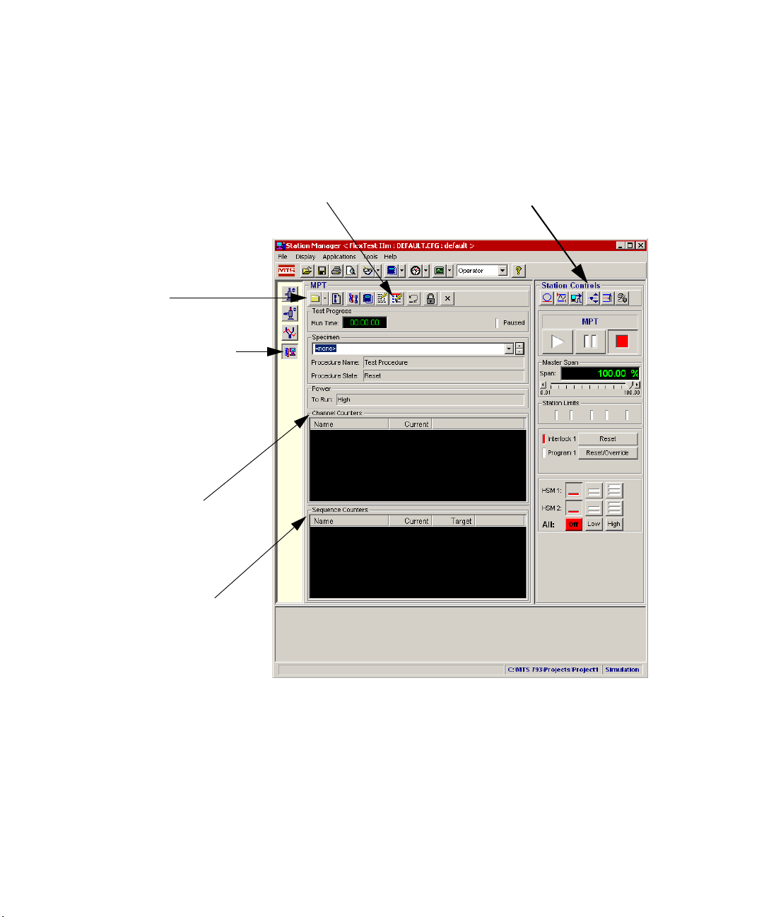
the display changes and appears as shown.
• The MPT control panel provides access to all the functions needed to create,
edit, and run procedures for the current station configuration.
• The run, stop, and hold controls pertain to procedures.
• Also, if the current procedure includes an Operator Event process, a special
panel appears in the initial display.
Note When you select MPT this way, you can create, edit, and run
procedures. You can also select an ‘edit only’ instance of MPT
(Applications > MultiPurpose TestWare (Edit Only)) to run one
procedure while editing other procedures.
MTS MultiPurpose TestWare® About MultiPurpose TestWare
21
Page 22
The MultiPurpose TestWare Interface
MPT application button
When you launch MPT this
button appears in the
applications control panel.
You can quickly select
among launched
applications with the buttons
in this panel.
Channel Counters
Channel Counters display
the cumulative count of
segments applied to
specific channels.
MPT toolbar
Sequence Counters
Sequence counters display
current and target counts for
processes. Individual process
counters are arranged
according to the process icons
on the Procedure Editor. Group
process counters are indented
to show nesting.
MPT Procedure Editor button
Displays the Procedure Editor and
Process Palette, as shown on the
next page.
Station Controls
You run MPT procedures with
the run, stop, and hold
controls.
MPT control panel The MPT control panel appears in the application area of Station Manager, as
shown.
About MultiPurpose TestWare
22
MTS MultiPurpose TestWare®
Page 23
Status and progress
indicators for
processes lets you
watch the progress
of the test
(not shown):
A blue arrow indicates that the process is
executing.
A red “X” indicates that the process is disabled.
A green arrow indicates that the process is
configured to issue a done signal immediately
without performing its programmed activity.
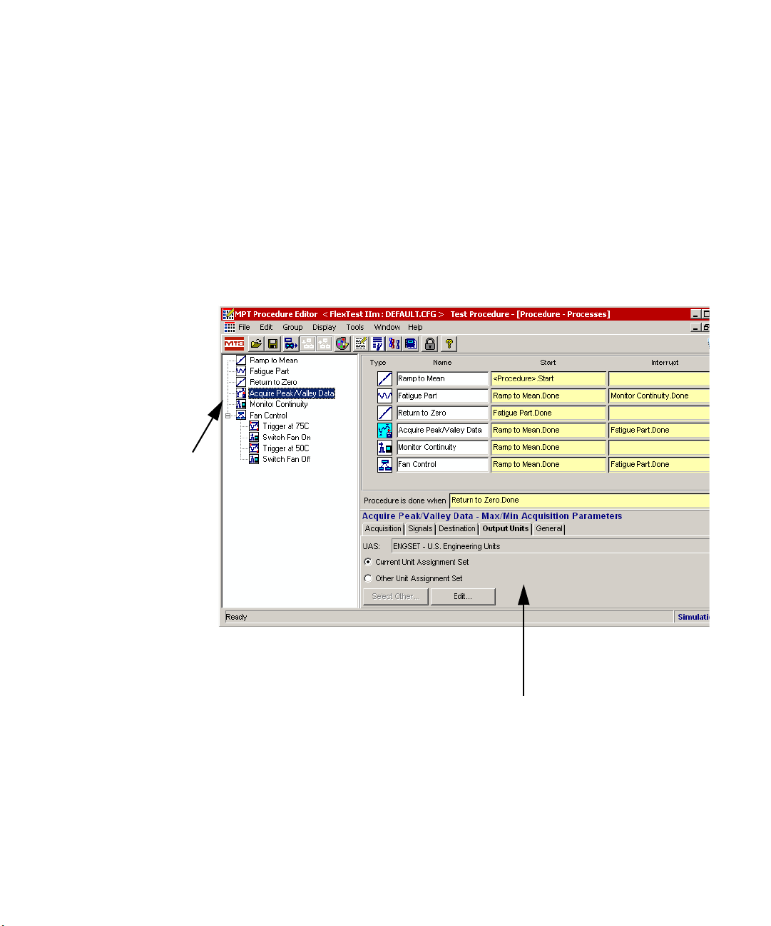
Procedure Editor
(default view)
The Procedure
Editor contains a
table on which you
build MPT test
procedures.
Navigation Pane
Provides a tree view
of the processes in
the procedure table
pane.
Active Process Parameters Pane
The parameters for the currently selected
process appear in this pane.
The MultiPurpose TestWare Interface
Procedure Editor The Procedure Editor contains a table on which you build MPT test procedures
by selecting, assigning parameters to, and sequencing individual test processes.
Test processes represent individual test activities.
The contents of the currently selected nesting level is displayed in the procedure
table pane. If a nested group process is selected, the general parameters for the
group are shown in the active process parameters pane.
Double-clicking on a parameter in the navigation pane or procedure table will
maximize the active process parameters pane. The contents of pane (default
view) and the expanded window are both editable. Minimizing or closing this
window restores the default view.
MTS MultiPurpose TestWare® About MultiPurpose TestWare
23
Page 24
The MultiPurpose TestWare Interface
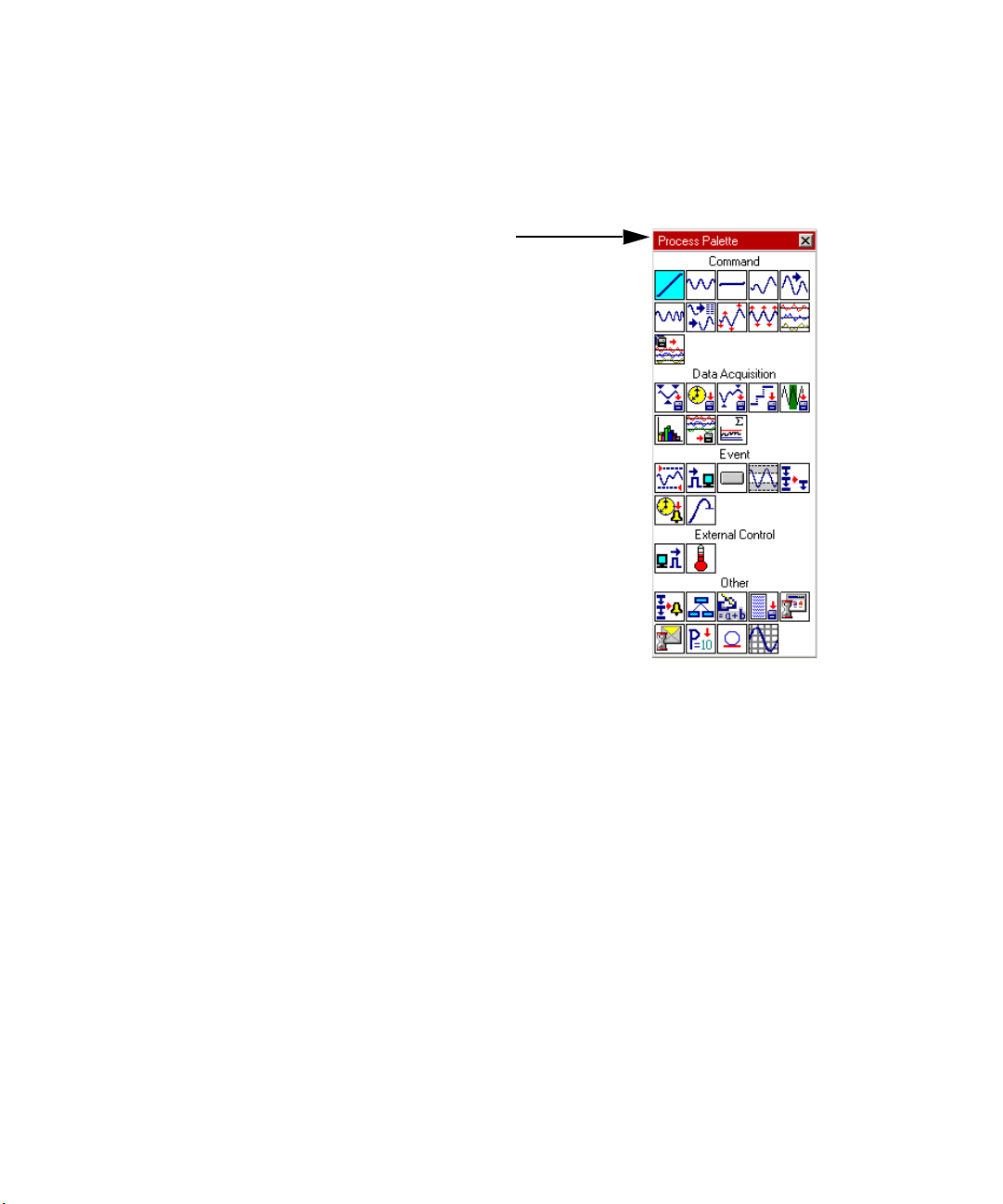
Process Pallete
Individual processes are
arranged on the palette by type.
You can double-click a process
on the Process Palette to copy
an instance of it to the table on
the Procedure Editor, or you can
use the drag-and-drop method.
Process Palette The processes available are displayed on the Process Palette. Individual
processes are arranged on the palette by type. You can double-click a process on
the Process Palette to copy an instance of it to the procedure table, or you can use
the drag-and-drop method.
About MultiPurpose TestWare
24
MTS MultiPurpose TestWare®
Page 25
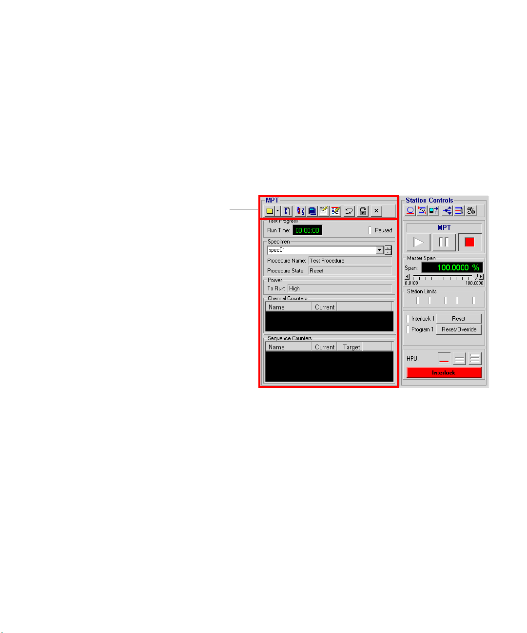
About the MPT Control Panel
The MPT control panel
includes a toolbar that
performs actions (like
unlocking procedures) and
provides access to editors
(like the MPT Procedure
Editor and the MPT
Specimen Editor) and the
MPT Specimen Log.
With the MPT control panel you can:
• Access common controls from the toolbar (including the MPT Procedure
Editor, the place where you build procedures)
• Monitor the test’s status and counter information (channel, sequence, and
run time counters)
• Create and rename MPT specimens
The MultiPurpose TestWare Interface
For more information For more information about setting MPT control panel preferences, see “MPT
MTS MultiPurpose TestWare® About MultiPurpose TestWare
Options Editor Control Panel Tab” on page 79.
25
Page 26
The MultiPurpose TestWare Interface
MPT Control Panel Toolbar
The buttons that comprise the MPT control panel toolbar provide quick access to
common commands and windows.
MPT Control Panel Toolbar (part 1 of 2)
I
TEM DESCRIPTION
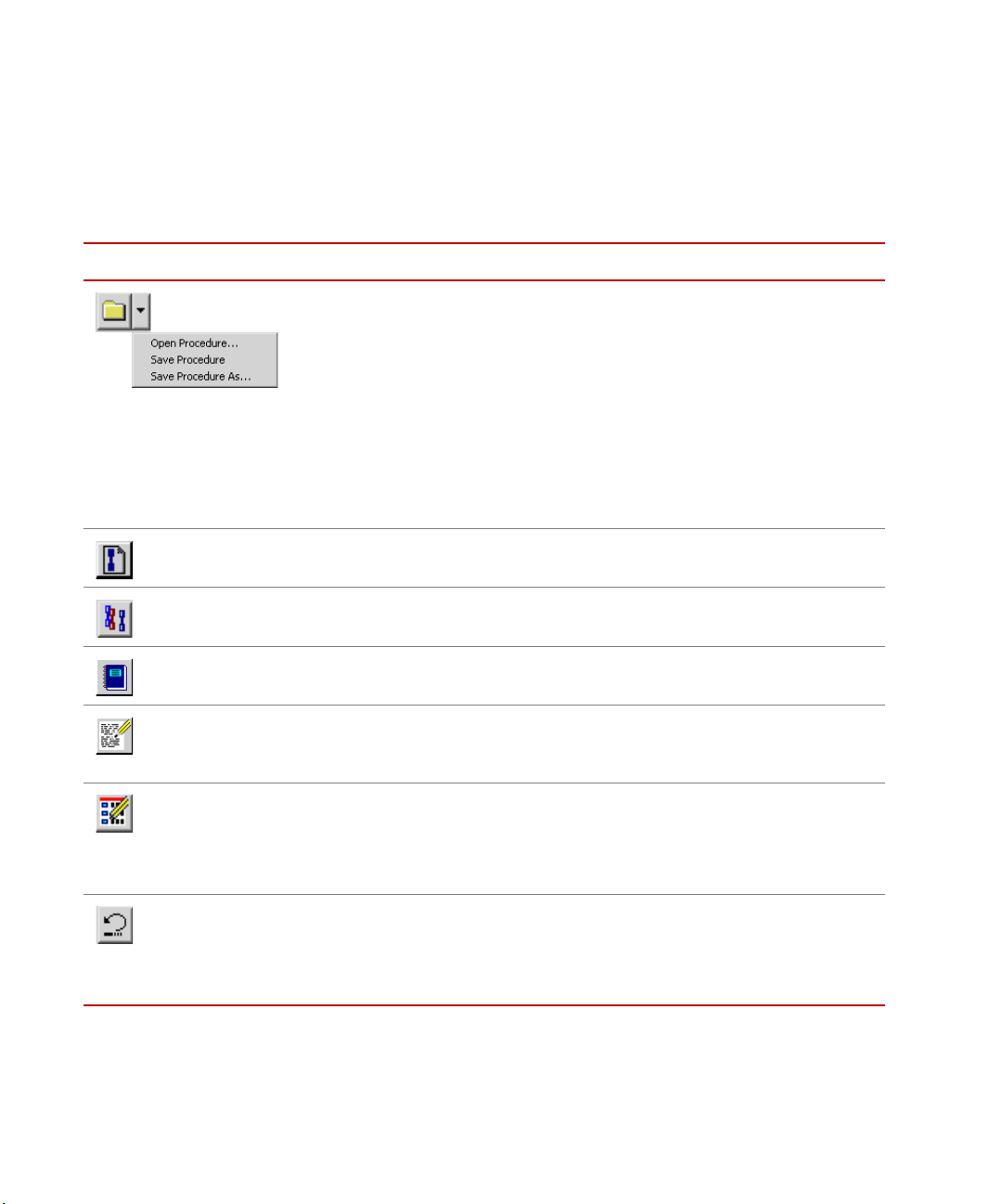
Displays the Open Procedure window, saves the current procedure, or displays
the Save Procedure As window.
You can use the Open Procedure window functions to navigate to, select, and
open an existing procedure. You can use the Save Procedure As window
functions to save the current procedure as a new file with a specified name and
location.
Note If you select Save Procedure for a procedure that has never been
Creates a new MPT specimen for the procedure that is currently loaded. The
new folder is immediately visible in the Specimen panel.
save, the application displays the Save Procedure As window. With
this window you can name the procedure and save it to the location
you desire.
About MultiPurpose TestWare
26
Displays the MPT Specimen Editor . You can use the MPT Specimen Editor to
create and edit multiple MPT specimens.
Displays the MPT Specimen Log which contains messages that pertain to the
current MPT specimen.
Displays the MPT Options Editor. With the MPT Options Editor, you can
customize the MPT interface to suit your needs by defining control options and
preferences.
Displays the MPT Procedure Editor, the place where you create and edit
procedures consisting of MPT test processes.
Note To edit a selected procedure on the MPT Procedure Editor, you must
first be in the Edit mode.
Resets the current procedure to the beginning. Pressing run after pressing reset
restarts the procedure from the beginning.
Note After the procedure completes, you must click Reset before you can
run the procedure again on the same MPT specimen.
MTS MultiPurpose TestWare®
Page 27
MPT Control Panel Toolbar (part 2 of 2)
I
TEM DESCRIPTION
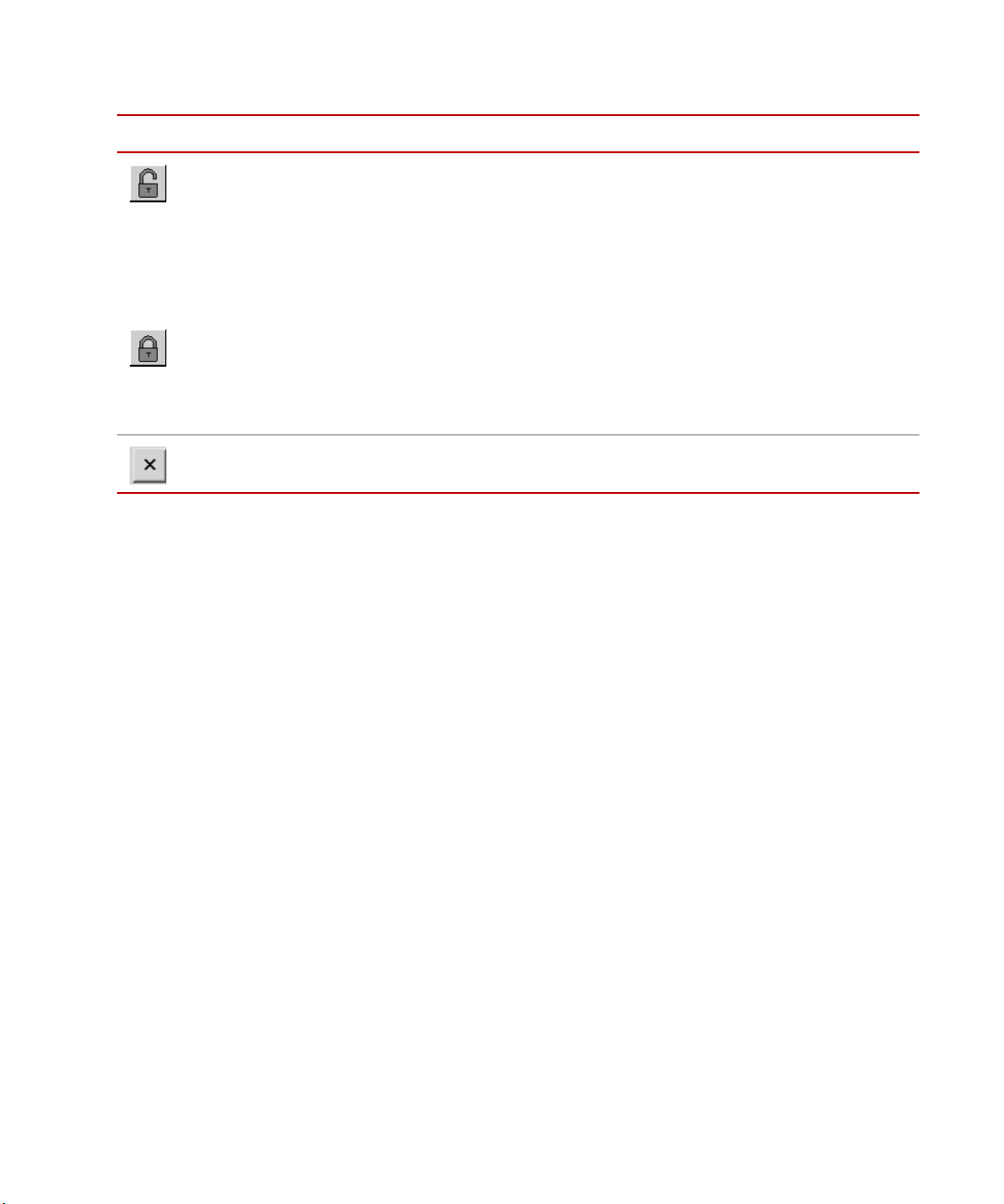
Changes between edit and execute test modes. To change (toggle between)
modes, click the edit /execute mode button.
The MultiPurpose TestWare Interface
Edit mode
You must be in edit mode to create or make changes to your procedure.
Note You cannot switch to edit mode if the procedure is running or holding.
You must be in the execute mode to run your test. The procedure automatically
switches to execute mode if you click run on the Statio n Controls panel.
Note When you change to execute mode, the MPT application becomes the
Execute mode
controlling application of the control channels used in the procedure.
You cannot use the Station Managermanual command controls on
the control channels used in the procedure.
Quits the MultiPurpose TestWare application.
For more information See “MPT Specimen Editor” on page 131.
See “About the MPT Procedure Editor” on page 36.
See “Edit mode” on page 27.
MTS MultiPurpose TestWare® About MultiPurpose TestWare
27
Page 28

The MultiPurpose TestWare Interface
MPT Test Progress Panel
The Test Progress panel displays the elapsed run time of the test that is in
progress and indicates if the test is currently paused.
I
TEM DESCRIPTION
MPT Test Progress Panel
Run Time
Displays the elapsed time of the current test (the elapsed run time does not
include time spent in hold or stop states).
You can turn the Run Time display on-and-off and select a display format
using the Control Panel tab of the MPT Options Editor.
To access the Run Time menu when the procedure is locked and reset, rightmouse click with the cursor positioned over the Run Time counter to display.
Select the Reset menu item to reset the Run Time counter to zero.
Paused
Indicates when the procedure has been paused by a Program Control process.
The paused state is not the same as the hold state.
• When the test is holding, you must click the run button to resume the test.
• When the test is paused, the test must be resumed by another Program
Control process (set to Program Resume).
For more information See “MPT Options Editor Control Panel Tab” on page 79.
For more information about pausing a test with the Program Control process, see
“About the Program Control Process” on page 400.
About MultiPurpose TestWare
28
MTS MultiPurpose TestWare®
Page 29
MPT Specimen Panel
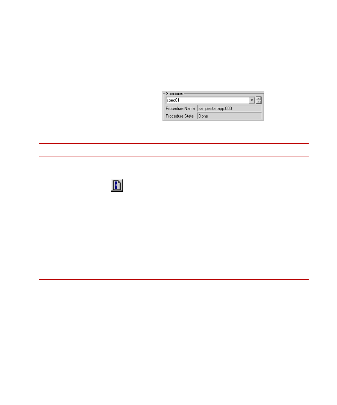
The Specimen panel displays the current MPT specimen selection and the
Procedure Name and Procedure State associated with the selected specimen. In
addition, you can use this panel to navigate to other MPT specimens displayed in
the Specimen list.
I
TEM DESCRIPTION
The MultiPurpose TestWare Interface
MPT Specimen Panel (part 1 of 2)
Specimen
Displays the MPT specimen that is linked to the procedure.
You can select the desired MPT specimen from the Specimen list or click
to create a new MPT specimen.
Use the up and down scroll arrows to select an available MPT specimen from
the list. You can rename the selected MPT specimen (if you are in edit mode)
by typing over the folder name in the Specimen box.
Note New MPT specimens that are created using the new specimen icon are
assigned names that are based on a default root name (for example,
“spec”) with an incremental number suffix. The default root can be
changed with the Project Manager application.
Note To cut, copy, paste, or delete the displayed MPT specimen name,
right-mouse click on the current MPT specimen name and select the
desired right-mouse menu item.
MTS MultiPurpose TestWare® About MultiPurpose TestWare
29
Page 30

The MultiPurpose TestWare Interface
I
TEM DESCRIPTION
MPT Specimen Panel (part 2 of 2)
Procedure Name
Displays the name of the current procedure selection. The procedure name is
established when you save the procedure.
Procedure State
Displays the current state of the procedure, which may be one of the following:
• Reset—The test is at the beginning but has not been started.
• In Progress—The test has started but is not yet completed.
• Done—The test has been completed.
Note To run the procedure on the same MPT specimen again, press Reset.
Otherwise, create a new MPT specimen for the next instance of
running the same procedure.
• Error—An error has occurred (you must click Reset to run the test
again).
For more information For more information about MPT specimens, see “Working with MPT
Specimens” on page 125.
About MultiPurpose TestWare
30
MTS MultiPurpose TestWare®
Page 31

MPT Power Panel
The Power panel displays the hydraulic supply pressure required to run the
selected test.
I
TEM DESCRIPTION
The MultiPurpose TestWare Interface
MPT Power Panel
To R u n
Displays the hydraulic pressure required to run the control channels in the
current procedure (hydraulic pressure options are High, High/Low, Off/
Interlocked, or Off).
Note Power status applies only to control channels. If a procedure does not
contain control channels, the power status has no effect on the
procedure. For instance, if you remove hydraulic power from a
procedure that does not include control channels, the procedure is still
valid.
You can specify the required hydraulic pressure for the control channels of the
current procedure using the Execution tab of the MPT Options Editor.
Note You must be in edit mode to change settings on the Execution tab.
The High selection applies to most testing situations. High requires you to
operate MPT with high hydraulic pressure applied to the station’s Hydraulic
Service Manifolds (HSM).
The Off/Interlocked and Off selections are typically used while you are
learning the application software or running test simulations.
The Off/Interlocked selection disregards active interlocks for the sake of
allowing you to run the test unhindered.
For more information See “MPT Options Editor Execution Tab” on page 62.
MTS MultiPurpose TestWare® About MultiPurpose TestWare
31
Page 32

The MultiPurpose TestWare Interface
MPT Channel Counters Panel
The Channel Counters panel displays the running total of completed command
channel cycles or segments during test execution.
I
TEM DESCRIPTION
MPT Channel Counters Panel
Channel Counters
Displays a running total of the cycles or segments that have been run during
the test for each command channel specified in the procedure.
The Channel Counters panel displays all channels that are selected for use
during a test. A channel does not have to be used in every process to be
displayed.
You can specify the Channel Counters display format using the Control
Panel tab of the MPT Options Editor. You must be in edit mode to change the
Control Panel settings.
To access menu items that pertain to Channel Counters position the cursor
over the Channel Counters display and perform a right-mouse click. When
you do this, the Reset Counters and Set Counters... menu items appear
(provided that the procedure is locked and in the reset state). The Reset
Counters selection resets all active channel counters to zero. With the Set
Counters... selection you can manually set each channel counter to a user
specified value.
For more information See “MPT Options Editor Control Panel Tab” on page 79.
About MultiPurpose TestWare
32
MTS MultiPurpose TestWare®
Page 33

MPT Sequence Counters Panel
The Sequence Counters panel displays process counters for each specified
counter using the selected process counter format.
MPT Sequence Counters Panel
I
TEM DESCRIPTION
The MultiPurpose TestWare Interface
Sequence Counters
Displays individual process counters. You can specify the counter type using
the General tab of each process parameters window.
• If you specified a Fixed counter, the counter label and counter are
displayed for the duration of the procedure.
• If you specified a Transient counter, the counter label and counter are
displayed only while the process is active.
For more information For more information about using counters, see “About Counters” on page 49.
MTS MultiPurpose TestWare® About MultiPurpose TestWare
33
Page 34

The MultiPurpose TestWare Interface
Note Applies to Time History
Output, Time History
Input, and Road
Surface Output
processes only.
About Process Specific Panels
Process specific panels display only when certain processes are selected from the
Process Palette and are configured specifically to display at or during run time.
Examples of some of these displays are shown below.
Profile Counter Panel
Process Status Panel
Operator Events Panel
For more information For more information about these panels, see “About MPT Processes” on page
84.
About MultiPurpose TestWare
34
MTS MultiPurpose TestWare®
Page 35

MPT Run/Stop/Hold Panel
The run/stop/hold panel controls run, stop, and hold test activities for the current
application. When you select MultiPurpose TestWare from the Applications
menu, it becomes the controlling application and “MPT” appears on this panel.
I
TEM DESCRIPTION
Starts the procedure. When you click this button, the run indicator blinks while
the procedure transitions from the current state to the “run” state. Once the run
state is achieved the indicator remains constant unless additional transitions or
program induced pauses occur. Additional blinks may occur depending on the
duration of the transition or pause.
Suspends all active command and data acquisition processes.
The MultiPurpose TestWare Interface
MPT Run/Stop/Hold Panel
Note Active limit detector and digital input processes remain active.
When you click hold, the hold indicator blinks while the procedure transitions
from the current state to the “hold” state. Once the hold state is achieved, the
indicator remains constant. To resume the run state from the hold state, click
run.
Note The hold button may be disabled if Ignore Hold Event is selected on
the MPT Options Editor window Execution tab.
Stops the procedure. When you click stop, the stop indicator blinks while the
procedure transitions from the current state to the “stop” state. Once the stop
state is achieved, the indicator remains constant.
MTS MultiPurpose TestWare® About MultiPurpose TestWare
35
Page 36

MPT Procedure Editor
The MPT Procedure
Editor includes the
menu, toolbar,
procedure table,
navigation pane, and
active process
parameter information
pane.
You create procedures
by populating the
procedure table with
test processes from the
Process Palette.
“Simulation” appears in the status bar when you run the “Demo”
(demonstration) System Loader program.
MPT Procedure Editor
About the MPT Procedure Editor
The MPT Procedure Editor is where you create procedures by combining and
defining the parameters of individual test processes available on the Process
Palette.
To display the MPT Procedure Editor, click on the icon in the MPT
toolbar.
About MultiPurpose TestWare
36
MTS MultiPurpose TestWare®
Page 37

MPT Procedure Editor Menu
The following menus are available on the MPT Procedure Editor window:
• Group Menu
• Display Menu
• Tools Menu
• MPT Procedure Editor Toolbar
Note When viewing the output files generated by the Print Procedure, Print
Group Menu
Use the Group menu commands to restore, navigate through, and control
specific Group table functions.
I
TEM DESCRIPTION
MPT Procedure Editor
Preview, and Print to File selections, items preceded by an asterisk (*)
have been changed since the procedure was last opened or saved.
Group Menu
Procedure
Next
Previous
Restores the main procedure table if it has been minimized or hidden.
Opens the Group table for the selected group process.
Note This command is only available when you select a Group process
icon.
Displays the parent procedure table for the current Group table.
Note This command is only available when you are in a Group table.
Display Menu
Use the Display menu commands to:
• Change between the test edit mode and test execution mode.
• Display the Process Palette.
• Display the MPT Specimen Log
MTS MultiPurpose TestWare® About MultiPurpose TestWare
37
Page 38

MPT Procedure Editor
Tools Menu
I
TEM DESCRIPTION
Use the Tools menu commands to display various editors used to customize the
MPT environment and/or the current procedure.
Tools Menu
Specimen Editor
Unit Set Editor
Options Editor
MPT Procedure Editor Toolbar
The buttons that comprise the MPT Procedure Editor toolbar provide quick
access to common commands and windows.
MPT Procedure Editor Toolbar (part 1 of 2)
I
TEM DESCRIPTION
Deletes the process (or processes) selected in the active procedure table.
Opens the next group table. This button is only active if there are multiple
group tables available.
Opens the previous group table. This button is only active if there are multiple
group tables available.
Displays the Process Palette. You can select processes from the palette to copy
to the MPT Procedure Editor, or you can drag and drop processes from the
palette to the MPT Procedure Editor.
Displays the MPT Specimen Editor.
Displays the Unit Set Editor.
Displays the Options Editor.
About MultiPurpose TestWare
38
Displays the MPT Options Editor. With the MPT Options Editor, you can
select control options and preferences for the current procedure.
Displays the MPT Variables Editor.
Displays the MPT Specimen Editor. You can use the MPT Specimen Editor to
create and edit multiple MPT specimens.
MTS MultiPurpose TestWare®
Page 39

MPT Procedure Editor Toolbar (part 2 of 2)
I
TEM DESCRIPTION
Displays the MPT Specimen Log for the current MPT specimen.
Changes between edit and execute test modes. To change (toggle between)
modes, click the edit /execute mode button.
MPT Procedure Editor
Edit mode
You must be in edit mode to create or make changes to your procedure.
Note You cannot switch to edit mode if the procedure is running or holding.
You must be in execute mode to run your test. The procedure automatically
Execute mode
switches to execute mode if you click Run on the Station Controls panel.
Note When you change to execute mode, MPT takes control of the various
resources used in the procedure, such as control channels, digital
output channels, and so on. You cannot use these resources with
Station Manager until you unlock the procedure and attain the edit
mode.
Trash can. Processes are not stored in the trash can as they are in the Windows
Recycling Bin. They are deleted immediately after you drag them to the trash
can icon.
For more information See “Process Palette” on page 84.
See “About the MPT Options Editor” on page 62.
See “MPT Specimen Editor” on page 131.
MTS MultiPurpose TestWare® About MultiPurpose TestWare
39
Page 40

MPT Procedure Editor
Process Type
Name
Start Trigger
Interrupt Trigger
Navigation
Pane
Active
Process
Parameters
Procedure Table
Access From the MPT Procedure Editor pane, the access paths are:
You use this pane to organize and synchronize the processes that make up your
test.
File > Open (or New) Procedure
Or
Group > Procedure
40
About MultiPurpose TestWare
MTS MultiPurpose TestWare®
Page 41

I
TEM DESCRIPTION
MPT Procedure Editor
Procedure Table
Process indicators
Typ e
Start
Interrupt
Procedure is done
when
Indicate the status of the adjacent process. Indicators have the following
meanings:
The process is enabled and active.
The process has been disabled.
The process is enabled, but configured to run zero times.
Displays the individual process icons that you have selected. You can doubleclick an icon to open the associated process parameters window. In addition, if
you right-click on an icon you can open the parameters window associated
with the process, open a new process (or group) table, enable or disable the
process, and delete the process.
Specifies the triggers or events that cause this process to start.
Specifies the triggers or events that interrupt this process.
Specifies the triggers or events that cause the end of the procedure.
MTS MultiPurpose TestWare® About MultiPurpose TestWare
41
Page 42

MPT Procedure Editor
Note Some processes
are optional and
appear on the
Process Palette
only when
purchased
separately.
Process Palette
Access From the MPT Procedure Editor window, the access paths are:
Use the Process Palette to select test processes by using their representative
icons.
Display > Process Palette
Or:
The Process Palette contains the icons of processes that you can add to the
procedure table to build a procedure.
For more information See “How to Add Processes to the Procedure Table” on page 85.
About MultiPurpose TestWare
42
MTS MultiPurpose TestWare®
Page 43

Chapter 6
Performing Common Tasks
Contents How to Start MultiPurpose TestWare 44
How to Display the MPT Procedure Editor 44
How to Create a New Procedure 44
Considerations for Test Design and Execution 45
How to Open a Procedure 47
How to Save a Procedure 47
How to Preview a Procedure 47
How to Print a Procedure 47
How to Run a Procedure 48
About Counters 49
Types of Counters 49
How to Display Counters and Status Panels 51
About the Clear Counters on Reset Function 53
About Working with Unit Assignment Set Editor 55
About the MPT Specimen Log 57
MTS MultiPurpose TestWare® Performing Common Tasks
43
Page 44

How to Start MultiPurpose TestWare
How to Start MultiPurpose TestWare
From Station Manager To start the MultiPurpose TestWare application, you must first start the Station
Manager application and open a station configuration.
Once the configuration file is open, on the Station Manager Applications menu,
click MultiPurpose TestWare to display the MPT control panel.
You can run existing procedures from the MPT control panel. If you want to edit
or create new procedures, you need to access the MPT Procedure Editor.
From other MTS
applications
From the Station Desktop Organizer Start Applications menu: click Station
Manager, open a station configuration, and on the Applications menu, click
MultiPurpose TestWare.
On the Project Manager tool bar: click the Station Manager icon, or from the
Applications menu, click Station Manager. Then on the Applications menu,
click MultiPurpose TestWare.
For more information For more information, see “About the MPT Procedure Editor” on page 36.
How to Display the MPT Procedure Editor
On the MPT control panel toolbar, click .
How to Create a New Procedure
When you start MPT a new (undefined) procedure is automatically created. To
create a new procedure any time MPT is active, from the MPT Procedure Editor,
select the File menu, then click New Procedure.
Even so, if you follow along and create a less complex version of the test
procedure, or even if you just review the pages without using your software, you
still benefit by learning the fundamentals of creating test procedures.
Note The hardware resources and label names provided in this section are for
illustration purposes only. Your hardware resources and label names
typically vary with the hwi file and station configuration file you use.
For more information If you would like to review a sample test design, see “Creating a Practice Test
Procedure” on page 153.
Performing Common Tasks
44
MTS MultiPurpose TestWare®
Page 45

Considerations for Test Design and Execution
Considerations for Test Design and Execution
Undesirable latencies
in test procedures
Design tests to
minimize undesirable
latencies
Other considerations
to minimize
undesirable latencies
One consideration of test procedure design is the potential for undesirable
latencies between test activities. There is, of course, a certain amount of latency
between test activities due to intra-system communication which cannot be
avoided. Latencies beyond this though, may be undesirable for some tests,
especially if your test involves rapid switching between test activities of short
durations. The way you design test procedures and manage the execution of test
procedures can minimize unwanted latencies.
If your command waveform is all in the same control mode, it is best to design
your test using a Profile file, and run the Profile file with the MPT Profile
process.
You create a Profile file with a spreadsheet application or the MTS Model 793.11
Profile Editor application. A Profile file consists of a series of segments. When
MPT runs the segments within a Profile file they are not vulnerable to delays (as
compared to executing a series of individual MPT command processes). MPT
queues multiple rows of the Profile file to the segment generator simultaneously,
and if you specify multiple passes, the output proceeds with the next pass without
delay.
Many tests, of course, require control mode changes in the command waveform.
In this case, you must choose individual MPT command processes as required,
and assign triggers to link their execution.
Triggering from one MPT process to the next occurs on the Microsoft Windows
workstation, which makes them vulnerable to undesirable latencies due to other
activity on the workstation. Likely candidates include networking, video drivers
without adequate hardware acceleration, and other communication with the
controller, including running other test stations simultaneously.
To reduce unwanted latencies in this scenario, minimize operations involving the
Microsoft Windows operating system while your test is running.
Avoid the use of third
party software
MTS MultiPurpose TestWare® Performing Common Tasks
MTS also recommends that you avoid running third-party software applications,
including virus-checking software, when running any of the MTS 793 software
applications. Testing has revealed that some third-party software can consume
the majority of the PC is available processing power. These applications, if run
along with MTS 793 software applications, may cause communication with the
controller to cease. Ultimately, this causes the station and applications on it to
terminate.
45
Page 46

Considerations for Test Design and Execution
Design elements that
may lock up your
You can inadvertently design an MPT procedure that can lock up your system.
The cause is generally from:
system
• Requesting too much data acquisition or command generation, or
• Setting up a group process to repeat continuously when it does not contain
command or data acquisition processes. To understand this, think of
processes in these categories:
– Command and Data Acquisition—These processes initiate activity
within the machine, and wait for it to complete.
– Immediate Action (Digital Output and Program Control)— These
processes execute an action and complete immediately.
– Detectors (Digital Input and Data Limit)—These processes complete
immediately if their condition is initially met.
Note If you create a repeating group process that contains only “Immediate
Action” and “Detector” processes, care must be taken so that the
detectors do not complete and repeat a number of times in quick
succession without waiting for some other test activity. For example, if a
data limit is set up in a repeating group with no other actions, and the
data value always causes a limit detect, the system may lock up.
For more information See “About Sequencing Processes” on page 87.
Performing Common Tasks
46
MTS MultiPurpose TestWare®
Page 47

How to Open a Procedure
1. From the MPT control panel (or from the MPT Procedure Editor), click the
2. Double-click the desired procedure, or click the desired procedure once,
How to Save a Procedure
From the MPT Procedure Editor, click the Save Procedure icon, or click the File
menu and select the desired save option.
Alternately, from the MPT control panel, on the toolbar, click the Open
Procedure icon’s pull down menu, then select the desired save option.
Note MultiPurpose TestWare automatically appends “.000” to the file name
How to Open a Procedure
Open Procedure icon. Alternately, from the MPT Procedure Editor, click
the File menu, then click Open Procedure to display the Open Procedure
window.
then click the Open button.
you type. If you do not want to include the .000 extension, type a period
(.) at the end of your file name.
How to Preview a Procedure
From the MPT Procedure Editor, select the File menu, then click Print Preview
to view your procedure on-screen. Items preceded by an asterisk (*) have been
modified since the procedure file was open.
How to Print a Procedure
From the MPT Procedure Editor, select the File menu, then click Print
Procedure.
Click Print to File to save the procedure to a text file.
MTS MultiPurpose TestWare® Performing Common Tasks
47
Page 48

How to Run a Procedure
How to Run a Procedure
Running a procedure begins with station preparation and physical specimen
installation, both tasks that you accomplish with the Station Manager application.
The following steps assume you have already done the following:
• Created a configuration file with Station Builder, and tuned control channels
and calibrated sensor/conditioner pairs
• Opened Station Manager and selected the configuration file
• Applied hydraulic pressure to the station
• Installed the physical specimen into the test fixturing
• Set station limits
• Set up readout devices to monitor station signals
• Opened MultiPurpose TestWare
• Selected a procedure
1. Create or select an MPT specimen
Performing Common Tasks
48
Before you can run a procedure, you have to either create a new specimen or
select an existing MPT specimen for the test.
The term “MPT specimen” refers to a directory of information associated
with a specific execution of a procedure—not the physical specimen being
tested.
Your test data, as well as the procedure you ran, messages generated during
the test, recovery information, and so forth, is captured in the MPT
specimen you create for this test.
A. To create a new MPT specimen:
On the MPT control panel toolbar, click and a new MPT
specimen appears in the list box (for example, (“spec01,” “spec02,”
and so forth.). Rename the new MPT specimen as desired.
B. To select an existing MPT specimen:
On the MPT control panel toolbar, select an existing MPT specimen
from the Specimen list box.
MTS MultiPurpose TestWare®
Page 49

About Counters
About Counters
2. Start your test.
On the Station Controls panel click the run button to start the test. Look at
and listen to your test station after you start the test. If everything seems
normal, you can let your test run to completion.
Note After the completion of a test you have to press the reset button or create
a new MPT specimen to run subsequent tests.
When you create a procedure with MPT, you define the parameters of each
process in the procedure, including counter parameters.
In procedures, counters are linear tools used to indicate test progress and
facilitate recovery. It is important to understand counters and to realize that how
you define a counter can affect your test outcome and, as a result, the data that is
generated from the test.
Note Counters are not the only tools provided by the MPT application to
indicate test progress. The MPT Procedure Editor displays special
symbols when individual processes are active.
The various types of counters available for procedures are displayed on the MPT
control panel, provided the MPT control panel has been configured to display
them.
For more information See “About the MPT Control Panel” on page 25 for more information.
See “Procedure Table” on page 40 for more information about process indicators.
Types of Counters
The most prominent counters on the MPT control panel are the Run Time
counter, the Channel Counters, and the Sequence Counters.
There are also specialized counters that display only in association with specific
types of processes, such as:
• Profile counters, that appear only with the Profile Command and Profile
with ALC processes
• Status counters, that appear only with the Time History Input, Time History
Output, and Road Surface Output processes
MTS MultiPurpose TestWare® Performing Common Tasks
49
Page 50

Types of Counters
This sample procedure includes a group process labeled “Cooling
Cycles,” which contains four nested processes (with indented
label names, “Trigger at 75C,” and so forth).
Name displays the assigned process label.
Current displays the current value of the counter.
Tar get displays the assigned number of times the process should
run (or repeat).
Run time counter The Run Time counter displays the elapsed time of the current test since the last
time it was reset.
Channel counters Channel Counters display a cumulative count of segments or cycles that have
been applied to a specific channel since the start of the test.
Sequence counters Sequence Counters display the progress of individual processes within the test.
They can be especially useful for procedures that contain nested groups, because
you can configure them to show test progress within the nested structure of the
procedure.
Profile counters Note Applies only to Profile and Profile with ALC processes.
Profile Counters display counters that increment according to special markers
that profile designers put in profiles.
Status counters Note Applies only to Time History Output, Time History Input, and Road
Surface processes.
Performing Common Tasks
50
MTS MultiPurpose TestWare®
Page 51

Status counters display Elapsed Time (or Distance) and Total Time (or To ta l
Distance) counters, and a Percent Completed status bar.
• Elapsed Time displays the time since the process started. Distance displays
the distance traveled since the process started, which is calculated from the
Vehicle Speed entry on the process’ Status tab.
• Tota l Tim e displays the anticipated total time required to complete the
process (this does not include any other processes that may be part of the
test). Tot a l Di s ta n ce displays the anticipated total distance required to
complete the process, calculated from the Vehicle Speed entry on the
process’ Status tab.
• The Percent Completed status bar displays the percentage relationship of
the elapsed time (or distance) versus the total time (or distance) for the
process (the status bar updates according to the update rate of the test,
typically every 10 seconds or so).
How to Display Counters and Status Panels
You can choose to show or hide the various types of counters and status panels on
the MPT control panel when running tests.
How to Display Counters and Status Panels
Note The Run Time Counter, Channel Counters, and Sequence Counters
display by default.
Display Channel and
To display Channel Counters and Sequence Counters:
Sequence Counters
1. Open the MPT Options Editor and select the Control Panel tab.
2. Locate the Counters panel.
3. Check the boxes as desired to show or hide the counters and to choose their
display format. By default these counters are displayed.
To display the Run Time counter:
1. Open the MPT Options Editor and select the Control Panel tab.
2. Locate the Test Progress panel.
3. Check the box as desired to show or hide the Run Time counter.
Display Status panels To display Status panels:
1. Open the relevant process on the procedure table (Time History Input, Time
History Output, and Road Surface Output) and select the Status tab.
MTS MultiPurpose TestWare® Performing Common Tasks
51
Page 52

How to Display Counters and Status Panels
2. Check the Show Status Panel at Run Time box as desired. By default
status panels are not displayed.
Note If you enable the Show Status Panel at Run Time box, you have the
option of having the status panel display the distance traveled by the
vehicle, for which you type a nominal vehicle speed for the distance
calculations.
Profile Counters To display profile counters, you must include a Profile Command or Profile with
ALC process in your procedure that uses a profile that includes the keyword
“Action.”
Display individual
processes on the
Sequence Counters
panel
The Sequence Counters panel displays by default, but each counter that populates
the Sequence Counters panel must be enabled for display individually. To do
this you must open each process on the procedure table to display its Parameters
window, select the General tab, then select the desired Counter Type option.
The Counter Type options are:
• None—The counter label and counter are not displayed on the Sequence
Counters panel.
• Transient—The counter label and counter are only displayed on the
Sequence Counters panel when the process is active. When the process
ends, transient counters disappear.
• Fixed—The counter label and counter are displayed on the Sequence
Counters panel for the duration of the test.
For more information For more information, see “Action and Counter Syntax” on page 498.
For information about changing default settings, see “How to Customize the
Default Template” on page 553.
Performing Common Tasks
52
MTS MultiPurpose TestWare®
Page 53

About the Clear Counters on Reset Function
About the Clear Counters on Reset Function
With the Clear Counters on Reset check box (found on the Specimen tab of the
MPT Options Editor), you can choose whether run time, channel counters, and
profile counters:
• Clear when you reset the test (default setting), or
• Continue to increment after reset
Note Sequence Counters are always cleared on reset as this counter is used
in the recovery process.
Reset counters manually If the Clear Counters on Reset control is disabled and you want to manually
reset counters, you can:
• Select a new specimen (before resuming or between tests), or
• Right-click to reset each type of counter individually (applies to run time
counters, channel counters, and profile counters)
Use the right-mouse
menu for run time
counters
On the MPT control panel, position the cursor over the run time counter
(ensuring the procedure is locked and reset), and click the right-mouse button to
display the Reset menu. With the Reset menu, you can reset the counter.
MTS MultiPurpose TestWare® Performing Common Tasks
53
Page 54

About the Clear Counters on Reset Function
With the Reset Counters selection you can
manually reset the channel counters to zero.
With the Set Counters... window you can
manually set counter values.
Use the right-mouse
menu for channel
counters
On the MPT control panel, position the cursor in the channel counter panel
(ensuring the procedure is locked and reset) and click the right mouse button. The
Reset menu appears, which includes Reset Counters and Set Counters...
selections.
Use the right-mouse
menu for profile counters
Performing Common Tasks
54
On the MPT control panel, position the cursor over the profile counter panel
when the counters are active and click the right-mouse button to display the
Reset Counters button. With the Reset Counters button, you can manually reset
the counters to zero.
Note The procedure does not have to be in the reset state to use the Reset
Counters button for profile counters. You can reset profile counters on-
the-fly, while the test is running.
MTS MultiPurpose TestWare®
Page 55

About Working with Unit Assignment Set Editor
Use the Unit Assignment Set Editor to create and modify unit assignment sets
(UAS). Unit assignment sets define the units of measurement that are available
for each dimension used in procedures.
Access From the MPT Procedure Editor windows the access path is:
Tools > Unit Set Editor
Note To use a UAS other than the default UAS, use the Unit Selection Tab of
the MPT Options Editor. To change the default UAS selection, use the
Project Manager application, or change the selection in the Station
Options window (Station Manager > Tools > Station Options > Unit
Selection).
Unit Assignment Set Editor (part 1 of 2)
I
TEM DESCRIPTION
About Working with Unit Assignment Set Editor
Open
Save
Save As
Delete
UAS Name
UAS File
Displays the Unit Assignment Set Open window. With this window you can
select the appropriate unit assignment set and to complete the open function by
selecting the Open button.
Saves any changes to the selected unit assignment set.
Displays the Unit Assignment Set Save As window. With this window you can
view and edit the selected UAS Name and to complete the save function by
selecting the Save button.
Deletes the selected unit assignment set.
Displays the name of the unit set currently selected.
Displays the file name of the unit set currently selected.
MTS MultiPurpose TestWare® Performing Common Tasks
55
Page 56

About Working with Unit Assignment Set Editor
Unit Assignment Set Editor (part 2 of 2)
I
TEM DESCRIPTION
Comment
Displays a comment about the selected UAS. We recommend you describe the
characteristics of the unit set you create.
Dimension and Units
Displays the dimensions and corresponding units used by the system software.
When you click a dimension name, the units assigned to the current set are
highlighted. To change a setting, click the dimension, and then click the
desired units.
Note You can quickly find an item in the Dimensions or Units list boxes
with the keyboard by typing the first letter of the desired item until it is
displayed. For example: To select the engineering force unit kN, type
the letter ‘k’ repeatedly until kN is highlighted in the list box.
Standard unit sets CGSSET - Centimeters-Grams-Seconds—Defines a set of units that is based
upon centimeters, grams, and seconds.
ENGSET - U.S. Engineering Units—Defines a set of units that contains
customary U.S. engineering units. It provides force-related units in “kip,” and
length-related units in “in.”
ENGSETSM - U.S. Engineering Units (small)—Defines a set of units that
contains customary U.S. engineering units. It provides force-related units, in
“lbf,” and length-related units in “in.”
SISET - SI (Systeme International d’Unites)—Defines a set of units that
contains customary international (metric) units. It provides force-related units in
“kN,” and length-related units in “mm.”
Performing Common Tasks
56
SISETSM - SI (Systeme International d’Unites) - small—Defines a set of
units that contains customary international (metric) units. It provides force, and
force-related units in “N,” and length-related units in “mm.”
SYSDEF - System Units Definition—Contains a copy of the units that are used
in the hardware and software to represent test values of interest.
MTS MultiPurpose TestWare®
Page 57

About the MPT Specimen Log
Use the MPT Specimen Log to display a record of test events in the Message
Logs window.
Access From the MPT Procedure Editor window, the access paths are:
Display > Specimen Log
Or:
MPT control panel >
About the MPT Specimen Log
The MPT Specimen Log records selected station and test events as they occur.
Note The MPT Specimen Log is displayed on the Message Logs window,
which can also display Station Log information (by selecting Station
Log in the Log list).
Events that can be logged include file events, resource conflicts, hydraulic status
changes, station state changes, detector activity, hardware over temperature
conditions, and full-scale changes.
Counter data is saved to the MPT Specimen Log automatically and manually .
Auto-archive function The MPT application automatically saves your MPT Specimen Log when it
accumulates at least 1000 log entries. When log entries are saved to the log file,
they are cleared from the MPT Specimen Log display.
Specimen log file
The default name for the current MPT Specimen Log file is specimen .log.
naming
MTS MultiPurpose TestWare® Performing Common Tasks
57
Page 58

About the MPT Specimen Log
CAUTION
Archived log files are named specimen000.log, specimen001.log,
specimen002.log, and so forth, up to specimen500.log.
Note The maximum number of log files that can be saved for a particular test
is 500.
Once you reach 500 log files, additional log files overwrite the oldest log files in
order (typically archiving restarts at specimen 000.log).
When a log file is saved (either manually or automatically), a log entry is made
noting the archival. This entry includes a time/date stamp and information about
where the file was saved. This entry becomes the first entry in the current log.
The MPT software can unexpectedly quit if you run out of disk space when
saving log files.
Quitting while a test is in progress can result in a loss of data.
If you think your test may generate an excessive number of MPT Specimen Log
entries, you should filter the messages written to the MPT Specimen Log with the
MPT Options Editor.
If the MPT application shuts down as a result of log files exhausting disk space,
you must remove some of the MPT Specimen Log files from your disk before
you restart the system software.
Message Logs Window (part 1 of 3)
I
TEM DESCRIPTION
Displays the Open Message Log File window where you can open any
archived or saved message log file (.log) you wish to view.
Saves message log entries to a log file.
If you click the Save icon and no log entries are selected, all of the
messages in the MPT Specimen Log are saved to file and the entire log is
cleared.
If you click the Save icon and one or more log entries are selected, all of
the messages up to and including the last selected message are saved to
file and cleared from the log.
Performing Common Tasks
58
MTS MultiPurpose TestWare®
Page 59

Message Logs Window (part 2 of 3)
ITEM DESCRIPTION
Closes the selected MPT Specimen Log and removes the log from the Log
list.
Opens the Message Log Print window.
With the Message Log Print window you can set certain print parameters
(such as Print Range and Print Filters), access the Print Setup window,
and initiate printing of the selected message log.
Displays the Message Log Print To File window. With the Message Log
Print To File window you can save your log as a text (.txt) file.
Adds your message entry to all active logs.
Note User entries are sent to all active logs (Station log, Basic
TestWare log, MPT Specimen log); user entries are not affected
by filtering attributes.
Deletes user-entered messages from the message log.
Note You can only delete user-entered messages.
Copies the selected Message Log entries to the clipboard.
About the MPT Specimen Log
Enables all the display options or allows individual display option enable/
disable functions.
If you click on the enable icon, all display functions (Date/Time, Severity,
Source) are enabled.
If you click on the down arrow, the individual display functions appear. If
you click on a function, the function state changes between enabled and
disabled. If a check mark appears next to the function, that function is
enabled.
Log
Displays the current log file. Use the down arrow to display other log files
that are available.
Log File
MTS MultiPurpose TestWare® Performing Common Tasks
Displays the path to the current log file.
59
Page 60

About the MPT Specimen Log
Message Logs Window (part 3 of 3)
I
TEM DESCRIPTION
Scroll to new entry
Disables or enables the MPT Specimen Log scrolling function. This
function allows the message log to automatically shift (scroll) to display
new entries as they occur.
Note By default, the Scroll to new entry box is enabled.
If you select Scroll to new entry, new log entries appear at the bottom of
the log as they occur. The log scrolls down automatically to ensure that the
latest entry is displayed.
If you clear the Scroll to new entry, the application adds new log entries
to the bottom of the log as they occur, but the log does not automatically
scroll down to the latest entry. New entries may not be visible unless you
manually scroll to the bottom of the log. With this selection you can
review the contents of the log without the window ‘jumping’ to the bottom
of the display each time a new log entry arrives.
For more information See “About Counters” on page 49.
For information about filtering MPT Specimen Log entries, see “MPT Options
Editor Specimen Tab” on page 73.
Performing Common Tasks
60
MTS MultiPurpose TestWare®
Page 61

Chapter 7
MPT Options Editor
Contents About the MPT Options Editor 62
MPT Options Editor Execution Tab 62
About Setpoint Use with MPT Test Procedures 66
About Command Hold and Stop Behaviors 67
About Data Acquisition Resulting From Command Stop Behavior 68
About Command Stop Behaviors and Automatic Setpoint Adjustments
69
About Transition States 70
MPT Options Editor Specimen Tab 73
MPT Options Editor Recovery Tab 74
About Test Recovery 75
MPT Options Editor Specimen Log Tab 77
MPT Options Editor Control Panel Tab 79
MPT Options Editor Properties Tab 80
MPT Options Editor Unit Selection Tab 81
MTS MultiPurpose TestWare® MPT Options Editor
61
Page 62

About the MPT Options Editor
About the MPT Options Editor
Use the MPT Options Editor to set preferences that are saved with the
procedure.
Saving option
preferences
When you create a new procedure, it contains default settings for all of the
controls in the Options Editor, such as preferences for the data file format,
command hold behavior, unit assignment set, and so forth. You can change these
default settings by modifying the “default.000” file.
For more information See “Default Templates” on page 553.
MPT Options Editor Execution Tab
Use the Execution tab on the MPT Options Editor to specify options related to
the execution of your test.
Access From the MPT control panel or MPT Procedure Editor window, the access path
is:
> Execution tab
Or, from the MPT Procedure Editor window, an alternate path is:
Tools > Options Editor > Execution tab
MPT Options Editor
62
MTS MultiPurpose TestWare®
Page 63

Options that are controlled from the Execution tab include:
• How the system responds when Hold is selected on the run, stop, hold
panel.
• Whether or not a test can be resumed if it has been stopped, but it has not
completed.
• Whether or not the Station Manager Span and Setpoint controls can affect
your procedure.
• What hydraulic state is required for the control channels in the procedure to
run.
• What happens to the command when the test is put in hold or stopped.
• Whether the application displays confirmation messages when actions that
affect test resumption occur.
Execution Tab (part 1 of 3)
I
TEM DESCRIPTION
MPT Options Editor Execution Tab
Hold State Support
Resume Test After Stop
Specifies how the Hold button on the Run/Stop/Hold panel operates.
Enable Hold—Clicking Hold puts the test in a hold state.
Ignore Hold Event—Hold is disabled and, if selected, has no effect.
Treat Hold As Stop—Hold operates identically to Stop .
Specifies whether or not you can resume a test after it is stopped.
Note This applies whether the test is stopped by an interlock, a
program control process, or the Stop button on the Run/Stop/
Hold panel.
If the enable option is not selected and a test is stopped, you must click the
Reset button or select a new MPT specimen before you can run the
procedure again.
MTS MultiPurpose TestWare® MPT Options Editor
63
Page 64

MPT Options Editor Execution Tab
I
TEM DESCRIPTION
Execution Tab (part 2 of 3)
Required Power
Command Hold Behavior
Command Stop Behavior
Setpoint
Specifies the hydraulic pressure setting required by the control channels in
a procedure to start and continue running.
Note Power status applies only to control channels. If a procedure does
not contain control channels, the power status has no effect on
the procedure. For instance, if a procedure without control
channels has a power status of High and hydraulic power is
removed from the station, the procedure is still valid.
The selections are High, High/Low, Off, and Off/Interlocked.
The High selection applies to most testing situations; it requires you to
operate MPT with high hydraulic pressure applied to the station’s
Hydraulic Service Manifolds (HSM).
The Off and Off/Interlocked selections are typically used while you are
learning the application software or running test simulations.
Off/Interlocked disregards active interlocks for the sake of allowing you
to run the test unhindered.
Specifies how command processes behave when the procedure transitions
to the hold state.
Specifies how command processes behave when the procedure transitions
to the stop state.
Enables or disables the Station Manager application’s Setpoint control on
the Setpoint and Span window.
MPT Options Editor
64
Enable—Allows the operator to change the Setpoint slider on the
Setpoint and Span window while the test is running.
Note The Disable and Reset option does not apply to the External
Command process.
Disable and Reset—Prevents the operator from changing the Setpoint
slider on the Setpoint and Span window while the test is running.
MTS MultiPurpose TestWare®
Page 65

Execution Tab (part 3 of 3)
I
TEM DESCRIPTION
MPT Options Editor Execution Tab
Span
Enables or disables the Station Manager application’s Span slider on the
Setpoint and Span window and the Master Span slider on the Stati on
Controls panel.
Enable—Allows the Span and Master Span sliders to affect the test
procedure command.
Note The Disable and Reset option does not apply to the External
Command process.
Disable and Reset—Prevents the Span and Master Span sliders from
affecting the test procedure command. The procedure plays out at 100%
span.
Confirm actions that may
affect resuming the test
Enables or disables this confirmation function.
When enabled (as indicated by a check mark in the box), this function
causes query windows to pop up. The intent of these windows is to point
out the potential loss of data and stimulate additional thought about the
possible effects of your actions.
An example of a query message is as follows:
“Reset will discard test progress in the current specimen. Do you really
want to reset?”
For more information For more information, see “MPT Run/Stop/Hold Panel” on page 35.
For additional information about Command Stop Behavior, see “About
Command Hold and Stop Behaviors” on page 67.
For more information, see “About Setpoint Use with MPT Test Procedures” on
page 66.
MTS MultiPurpose TestWare® MPT Options Editor
65
Page 66

About Setpoint Use with MPT Test Procedures
About Setpoint Use with MPT Test Procedures
General
considerations
Differences between
Setpoint Enabled and
Relative Endlevels
There are many reasons that you may or may not want the operator to have the
ability to change the Station Manager application’s setpoint control while the test
procedure is running.
In general, you typically want to prevent the operator from changing the setpoint
when performing tests that include control mode switches. So when you are
creating test procedures that perform control mode switches, select Disable and
Reset for the Setpoint control.
The Setpoint Enabled setting on the MPT Options Editor applies to the
execution of the entire test procedure. The Relative Endlevels setting available
in the Command tab of some command processes applies only to the execution
of the associated process.
Setpoint Enabled is typically used in applications where the test designer wants
to give the operator control of the reference level while the test is in progress.
These applications also typically run the entire test in a single control mode.
"Relative Endlevels" instructs that specific process to interpret its endlevels
relative to the segment generator's command when the process begins. This does
not give the operator the ability to change the reference point dynamically. It is
often used after a modeswitch. For example, ramp in load control to particular
load, then switch to displacement and ramp 3 mm relative to where the actuator
is.
Setpoint Enabled and Relative Endlevels are independent features, and are rarely
used at the same time.It is possible to use both of these features together; their
effect is additive.
Consideration for dual
compensation control
modes
MPT Options Editor
66
If you want to run your test procedure on a station that has a dual compensation
control mode, you need to be aware of the compensation type selected for the
control mode.
If the compensation type is Amplitude Control Only, do not disable the Station
Manager application’s setpoint with this control (that is, select Enable; do not
select Disable and Reset).
The reason is because a mode switch into a dual compensation control mode with
this type of compensation puts an offset into the setpoint (the offset provides a
“bumpless” mode switch). If you disable the setpoint (with the MPT Setpoint
control), you cannot remove the offset.
MTS MultiPurpose TestWare®
Page 67

If you want to run your test procedure on a station that has a dual compensation
control mode in which the compensation type is Mean and Amplitude Control,
you may disable the setpoint without any adverse effect.
For more information about how the setpoint control is affected by dual
compensation control modes, see the 793 Control Software manual (PN 100-147-
130).
About Command Hold and Stop Behaviors
The Command Hold Behavior and Command Stop Behavior functions allow
you to specify how an active MPT command process behaves when a procedure
transitions to the hold or stop states.
The following selections are the same for each control:
• Stay at Level—The waveform holds/stops at the current level.
• Ramp to Mean—The waveform ramps to mean.
• Ramp to Zero—The waveform ramps to zero.
• Taper to Mean—The waveform tapersto mean.
About Command Hold and Stop Behaviors
• Taper to Zero—The waveform tapers to zero.
The transition times for all ramp and taper functions are specified using the
Command Options tab on the Station Manager’s Channel Options window. The
default transition time is two seconds.
For more information about specifying command options, see the MTS 793
Control Software manual.
Special consideration If the procedure ends normally, and the Command Stop Behavior is set to
Ramp to Mean or Taper to Mean, the signal may not respond as you expect.
When a procedure ends normally (without being manually held or stopped), all of
its processes end normally, and then the Command Stop Behavior is run. In
these situations, Ramp to Mean and Taper to Mean settings behave like a “stay
at level” setting, and the Taper to Zero setting behaves like a “ramp to zero”
setting. The Ramp to Zero setting works as expected.
MTS MultiPurpose TestWare® MPT Options Editor
67
Page 68

About Data Acquisition Resulting From Command
Entering Stop
Counts as 3 command and
data acquisition cycles
Taper to Level
Counts as 5 command and
data acquisition cycles
Test is
stopped
Operator hits
Stop button
Test stops,
then restarts
Waveform is back
up to full amplitude
Test is
done
Start
About Data Acquisition Resulting From Command Stop Behavior
When a test is stopped by an operator, MPT continues to acquire data through all
subsequent transition periods.
Example Suppose you are running a procedure with a cyclic waveform, and wish to
acquire data on all the command cycles. The procedure requires 100 command
cycles and 100 data acquisition cycles, where 1 cycle=1 second.
You push the Stop button during the test, and it takes 3 seconds to taper to zero.
Those 3 cycles count as command and data acquisition cycles.
Then you push the Start button. It takes 5 seconds for the system to taper back up
to full amplitude. Those 5 cycles also count as command and data acquisition
cycles.
When the test reaches its “natural” done state (after 100 cycles,) it performs 100
command cycles and 100 data acquisition cycles, 8 of which are tapered.
Note It is important to realize that, because of the 8 tapered cycles, some data
points (those that are smaller than the specified sensitivity) might be
missed if you are taking peak/valley data.
MPT Options Editor
68
MTS MultiPurpose TestWare®
Page 69

About Command Stop Behaviors and Automatic
About Command Stop Behaviors and Automatic Setpoint Adjustments
Note When you enable Setpoint, the Return to Zero and Taper to Zero
functions operate relative to the Setpoint, not to absolute zero.
If you enable Setpoint and Span and set Command Stop Behavior to Stay at
Level, you may find that Setpoint increases unexpectedly if you stop, unlock,
reset, and restart the test. This also applies if remove and then turn hydraulics on.
The reason for this is that, using the previously described conditions, Setpoint
automatically shifts by the amount of offset present when the procedure was
stopped.
Example Suppose you run a procedure in which you run a ±10 mm cyclic command from a
mean level of 20 mm. You enable Span and Setpoint and select a Command
Stop Behavior of Stay at Level. You set Span to 100% and Setpoint to 0 mm.
When the actuator is at 20 mm, you stop the test. This causes the actuator to stop
and hold at 20 mm. Then you unlock the procedure and resume the test. In this
situation, the Setpoint value automatically increases to 20 mm, causing the
actuator to travel to mean level of 40 mm before resuming the ±10 mm cyclic
waveform.
Avoiding automatic
Setpoint adjustments
Example Suppose you run a procedure similar to the one in the previous example, except
Making manual
Setpoint adjustments
To avoid this behavior and run the test relative to the original Setpoint, select a
Command Stop Behavior of Ramp to Zero or Taper to Zero. This way, when
you unlock MPT, the commanded level is equal to the current Setpoint value.
you select a Command Stop Behavior of Ramp to Zero. When the actuator is
at 20 mm, you stop the test. This causes the actuator to ramp to 0 mm at the
system ramp rate. Next, you unlock the procedure and resume the test. In this
situation, the Setpoint value remains 0 mm, and the actuator ramps at the same
rate back to 20 mm before executing the ±10 mm cyclic waveform.
If the desired combination of Setpoint and Command Stop Behavior for your
situation results in a Setpoint shift, you have to manually adjust the Setpoint to
the desired position before you restart a test.
MTS MultiPurpose TestWare® MPT Options Editor
69
Page 70

About Transition States
About Transition States
Of the seven test states in MPT, there are four Entering and Exiting states:
Entering Stopped, Exiting Stopped, Entering Hold, and Exiting Hold. These
states could be described as “transition states”; that is, when MPT is leaving one
state and entering another, such as changing from a Running state to a Holding
state. Sometimes these transitions are instantaneous, but they still exist.
How long the test remains in a transition state depends on the test parameters you
have chosen, using two separate windows: the Execution tab on the MPT
Options Editor and the Command Options tab on the Station Manager’s
Channel Options window.
MPT Execution tab Use the MPT Execution tab to select the following Command Hold and
Command Stop Behaviors:
• Stay at Level
• Ramp to Mean
• Ramp to Zero
• Taper to Mean
Station Manager
Command Options tab
Example The Entering Hold state lasts as long as it takes the system to move from the
MPT Options Editor
70
• Taper to Zero
Use the Station Manager Command Options tab to set the times for these
behaviors:
• Taper Times
• Ramp Times
• Begin/End Times
• Setpoint/Span Times
See the MTS 793 Control Software manual (PN 100-147-130) for more
information.)
Running state to the Holding state. If you chose Stay at Level, the Entering Hold
state would be instantaneous. If you chose Ramp to Mean or Ta pe r to Mean,
then this state would exist for a longer time because time is needed to transition
from the current level to the level state.
MTS MultiPurpose TestWare®
Page 71

About Transition States
The amount of time the test remains in a state also results from the time you have
specified on the Station Manager Command Options tab:
• If you select a Ramp option for Command Hold Behavior or Command
Stop Behavior in MPT, the Ramp Times you specify in Station Manager
Command Options are used. When you click Hold or Stop while a test is
running, the test assumes a transition state during the ramp. If you click Run
to resume the test, the test also assumes a transition state during the ramp.
• If you select a Ta pe r option for the Command Hold or Stop Behavior, the
Taper Times you specify in Station Manager Command Options are used.
When you click Hold or Stop while a test is running, the test assumes a
transition state during the taper. If you click Run to resume the test, the test
also assumes a transition state during the taper.
• If you select a tapered waveform in a Cyclic Command, Profile, or Profile
with ALC process in MPT, the Begin/End Times you type in Station
Manager are used. Those tapers appear only at the very beginning and the
very end of the waveform generated by these processes. These tapers do not
occur in a transition state because they are considered part of the test (the
tapered cycles are counted).
The following diagram shows a test with a Sine Tapered waveform, Ramp to
Mean on hold, and Taper to Zero on stop. It also shows each of the program states
within the test:
MTS MultiPurpose TestWare® MPT Options Editor
71
Page 72

About Transition States
Program States
Click
Run
Click
Hold
Click
Run
Click
Stop
Click
Run
Click
Run
User Actions
For more information See “About Command Hold and Stop Behaviors” on page 67 for more
information.
MPT Options Editor
72
MTS MultiPurpose TestWare®
Page 73

MPT Options Editor Specimen Tab
Use the Specimen tab to determine the storage mode and format of the data that
is written to MPT specimens when you run procedures.
Access From the MPT control panel or MPT Procedure Editor window, the access path
is:
> Specimen tab
Or, from the MPT Procedure Editor window, an alternate path is:
Tools > Options Editor > Specimen tab
Specimen Tab (part 1 of 2)
I
TEM DESCRIPTION
MPT Options Editor Specimen Tab
Data File
Data File functions control how data is added to the data file and data format.
In addition, it controls the type of time stamp that is used in association with
the data.
Mode Append—Causes new data to be added to the end of data files.
Mode Overwrite—Clears the MPS specimen data file (and user-specified
files) when you start a new test run (that is, when you click Run after the test
has been reset), which causes new data to write over existing data in data files.
Format Plain—Writes space-delimited data. This is the most useful format for
direct printouts.
Format Lotus—Writes comma-delimited data with text strings in double
quotes (sometimes referred to as the CSV format). Use this format when you
plan to import data files into Lotus 1-2-3™.
Format Excel—Writes tab-delimited data. Use this format when you plan to
import data files into Microsoft Excel.
Time Stamp—Selects which signal is used to timestamp data records in the
data files. Time is the elapsed time from run to reset. Running Time is the
time from run to reset minus the time attributed to the Hold or Stop functions.
MTS MultiPurpose TestWare® MPT Options Editor
73
Page 74

MPT Options Editor Recovery Tab
I
TEM DESCRIPTION
Specimen Tab (part 2 of 2)
Specimen Log
Append—Causes new messages to be added to the end of the MPT Specimen
Log file.
Overwrite—Clears the MPT Specimen Log when you start a new test (that is,
when you click Run after the test has been reset), which causes new messages
to write over existing messages in the MPT Specimen Log file.
Clear Counters on
Reset
Enables and disables the clear function for the Run Time, Channel Counters,
and Profile Counters (it does not affect the Sequence Counters).
When enabled, the affected counters are cleared (reset to zero) whenever you
click the Reset button.
When disabled, the affected counters are not cleared (reset to zero) when you
click the Reset button.
Not resetting the counters can affect various test related functions. For
example, it can affect counter related limits (not resetting may cause you to
exceed a segment or cycle related limit). Counter resets are sometimes used to
indicate the start of a new test in your data file. Without the resets, multiple
iterations of a test may be viewed as one long test.
MPT Options Editor Recovery Tab
Use the Recovery tab to determine how often the application saves a “snapshot”
of the test state and status.
MPT Options Editor
74
Access From the MPT control panel or MPT Procedure Editor windows, the access path
is:
> Recovery tab
Or, from the MPT Procedure Editor window, an alternate path is:
Tools > Options Editor > Recovery tab
MTS MultiPurpose TestWare®
Page 75

The snapshots of the test state and status can be used to restart a test that was
interrupted by an event (for example, a power failure or interlock).
I
TEM DESCRIPTION
About Test Recovery
Recovery Tab
Recovery Settings
About Test Recovery
What is saved Information saved to the recovery file includes:
Enable saving recovery status—Enables the recovery feature and specifies
how the progression of the test state and status is saved.
Note MTS recommends you leave this feature enabled unless you have
strong reasons to disable it.
Upon program state change—Saves the test status whenever the run, stop, or
hold buttons are clicked on the Station Controls panel (including interlocks).
At least every—Saves the test status at a regular time interval (user specified).
When you enable the recovery feature, the application updates a recovery file
(saved in the MPT specimen) at the intervals you specify.
Snapshot intervals can be set using the program state changes (includes Run to
Stop or Stop to Run state changes, including interlocks) and time intervals that
you specify.
You can use a recovery file to restart a test even if the test was running during the
last snapshot. You cannot restart tests if they have completed or have been reset.
• A copy of the procedure. (It is possible to edit a procedure, then run it
without saving it. In this situation, the test status contains the information
used in the execution, not the original procedure.)
• The active group and individual processes. It also identifies how much of
each process is complete.
• The current program state (Run, Hold, Stop). When recovering a test, if the
program was running or holding, the test is restored in the Stop state.
• The state of the sequence counters and the channel counters.
MTS MultiPurpose TestWare® MPT Options Editor
75
Page 76

About Test Recovery
What is not saved When you recover a test, the test status is restored to the point where the last
snapshot was taken.
• If the test is stopped by an uncontrolled event (such as power failure or
application failure), any data not saved to disk at the point of the shutdown
is lost.
• If data was being transferred from the data buffer to the computer, data that
had not been transferred is lost.
DIO settings are not restored during the MPT recovery process. For information
about DIO settings, see the MTS 793 Control Software manual.
Recovery accuracy There are two measures of “accuracy” associated with a saved test status:
• How old is the snapshot? If the snapshot is taken one minute before the test
stops, many additional cycles may be applied to the MPT specimen that the
test status would not know about.
• How consistent is the snapshot? If the snapshot is taken while the test is
running, each active process is checked in sequence. This results in test
status data that is taken at slightly different times.
Recovery
considerations
Review the following characteristics of the test recovery feature to understand
the advantages and disadvantages of recovering a test under different
circumstances.
• Recovering a test that was saved periodically provides test status data that is
relatively accurate in relation to the point where the test stopped. The
shorter the period, the closer the test status is to the point of failure.
However, saving a test does require additional processor time. If the
autosave rate is too fast, the accuracy of the data acquisition processes (data
output and communication between processes) can be adversely affected.
• Each autosave action overwrites the test status. If the system experiences an
uncontrolled shutdown, (power fails) while the system is saving the test
status, test status recovery is probably not possible.
• The test status maintains a copy of the procedure when entering the Execute
mode in MPT.
MPT Options Editor
76
MTS MultiPurpose TestWare®
Page 77

MPT Options Editor Specimen Log Tab
Use the Specimen Log tab on the MPT Options Editor to filter the messages
written to the MPT Specimen Log. You can also specify what items are
displayed in the Message Logs window.
Access From the MPT control panel or MPT Procedure Editor window, the access path
is:
> Specimen Log tab
Or, from the MPT Procedure Editor window, an alternate path is:
Tools > Options Editor > Specimen Log tab
If your test generates an excessive number of messages, you should filter what
messages are written to the log to avoid exhausting disk space.
For instance, you can change the Source filter from All Applications to This
Application Only to keep Station Manager messages out of the MPT Specimen
Log.
MPT Options Editor Specimen Log Tab
Specimen Log Tab (part 1 of 2)
I
TEM DESCRIPTION
Message Capture
Controls the severity level and source of the information that is written to the
MPT Specimen Log.
Minimum Severity sets the severity level that must be reached before a
MultiPurpose TestWare writes a message to the Specimen Log file. There are
five levels:
• Diagnostic—Writes Diagnostic, Information, Warning , Error, and
Fatal Error messages.
• Information—Writes Information, Warning , Error, and Fatal Error
messages; does not write Diagnostic messages.
• Warning—Writes Warnin g, Error, and Fatal Error messages; does not
write Diagnostic and Information messages.
• Error—Writes Error and Fatal Error messages; does not write
Diagnostic, Information, and Warning messages.
MTS MultiPurpose TestWare® MPT Options Editor
77
Page 78

MPT Options Editor Specimen Log Tab
Specimen Log Tab (part 2 of 2)
I
TEM DESCRIPTION
• Fatal Error—Writes only Fatal Error messages; does not write
Diagnostic, Information, Warning, and Error messages.
Source—Selects the information source from which the log is built.
• This Application Only—Records messages from the MPT application
only.
• All Applications—Records messages from other sources, such as the
Station Manager application.
Archive Auto Deletion Important Enabling this control may result in the inadvertent deletion of
specimen log entries. The Specimen Log is unlikely to exceed
the internal limit of 500 Specimen Log files for a given MPT
specimen (unless your procedure is generating an excessive
number of messages). Therefore, MTS recommends that you
disable this control if you routinely use new MPT specimens from
test-to-test. Disabling this control ensures that you are able to
recover relevant log data for your MPT specimens in the future.
This control enables or disables the auto deletion function and sets the deletion
interval in days.
MPT Options Editor
78
The Specimen Log archive has an internal limit of 500 Specimen Log files,
with each file containing approximately 1000 messages. Once 500 archived
files are accumulated and a new archive file is generated, the oldest archive file
is automatically deleted to make room for the newest archive file.
The Archive Auto Deletion control lets you program when archived files are
deleted in terms of days (within the internal limit of 500 archived files).
To enable the Archive Auto Deletion function, click in the Delete Older Than
checkbox such that a check mark appears in the box. If the check mark appears
in the box, the function is enabled.
Set the deletion interval using the scroll arrows to change the number of days
displayed. The scroll arrows are only active if the Archive Auto Deletion
function is enabled.
MTS MultiPurpose TestWare®
Page 79

MPT Options Editor Control Panel Tab
Use the Control Panel tab to specify what information is displayed on the MPT
control panel.
Access From the MPT control panel or MPT Procedure Editor window, the access path
is:
> Control Panel tab
Or, from the MPT Procedure Editor window, an alternate path is:
Tools > Options Editor > Control Panel tab
Control Panel Tab (part 1 of 2)
I
TEM DESCRIPTION
MPT Options Editor Control Panel Tab
Test Progress
Specimen
Enables and disables the Run Time portion of the Test Progress panel on the
MPT control panel. You can also change the Run Time panel display format.
Run Time—Enables/disables the Run Time display. If Run Time is disabled,
the Run Time display does not appear on the Tes t Pro g res s panel
Display Format—Changes the Run Time display format. The format options
are HH:MM:SS (hours:minutes:seconds) and cumulative time units.
Enables and disables the Procedure Name and Procedure State portion of the
Specimen panel.
If the Procedure Name or Procedure State is disabled, the respective display
does not appear on the Test Progress panel.
Procedure Name—Displays the name of the current procedure.
Procedure State—Displays the current procedure state.
MTS MultiPurpose TestWare® MPT Options Editor
79
Page 80

MPT Options Editor Properties Tab
I
TEM DESCRIPTION
Control Panel Tab (part 2 of 2)
Station Status
Enables and disables the Power panel on the MPT control panel.
If Power is disabled, the Power panel does not appear on the MPT control
panel.
Counters
Enables and disables the Channel Counters and Sequence Counters. In
addition, it controls the counter display format.
Channel Counters—Displays the Channel Counters when enabled
Sequence Counters—Displays the Sequence Counters when enabled
Display Format—Controls the Channel Counters and Sequence Counters
display format. The format options are:
• Cycles - Displays the total number of cycles that have been run.
• Segments - Displays the total number of segments that have been
run.
For more information See “MPT Test Progress Panel” on page 28.
See “MPT Channel Counters Panel” on page 32.
See “MPT Sequence Counters Panel” on page 33.
MPT Options Editor Properties Tab
MPT Options Editor
80
Use the Properties tab to type information that is saved with the procedure.
Access From the MPT control panel or MPT Procedure Editor window, the access path
is:
> Properties tab
Or, from the MPT Procedure Editor window, an alternate path is:
Tools > Options Editor > Properties tab
MTS MultiPurpose TestWare®
Page 81

You can type a process summary, identify the procedure, describe the test, or
write instructions to the test operator. This information appears in the Print
Preview window.
I
TEM DESCRIPTION
MPT Options Editor Unit Selection Tab
Properties Tab
File Name
Description
Author
Displays the name and path of the current procedure selection.
Type a description or other information about the procedure here.
Type the author’s name here.
MPT Options Editor Unit Selection Tab
Use the Unit Selection tab on the MPT Options Editor to assign a different unit
assignment set to the current procedure.
Access From the MPT control panel or MPT Procedure Editor window, the access path
is:
> Unit Selection tab
Or, from the MPT Procedure Editor window, an alternate path is:
Tools > Options Editor > Unit Selection tab
Unit Selection Tab (part 1 of 2)
I
TEM DESCRIPTION
UAS Comment
Selection list
Displays a description of the selected unit assignment set.
Displays a list of the defined unit assignment sets. The currently selected set is
shown.
MTS MultiPurpose TestWare® MPT Options Editor
81
Page 82

MPT Options Editor Unit Selection Tab
I
TEM DESCRIPTION
Unit Selection Tab (part 2 of 2)
Use Station Unit
Assignment Set
Edit...
Note By default, this control is enabled in the default template. To disable
this control for new procedures, you must disable it in the default
template.
When enabled for existing procedures: Causes the procedure to acquire the
current default UAS selection. If this box was disabled when you opened a
procedure and you enable it while editing the procedure, you will see the units
in your procedure change from the UAS assigned when you opened the
procedure to the UAS set in the registry. The new UAS assignment are not
permanent until you save the procedure. If you close without saving, the UAS
assignment reverts to the set assigned when you opened the procedure.
When enabled for new procedures: Causes new procedures to open with the
UAS selection set in the registry.
When disabled for existing procedures: With this control, you can select and
edit any UAS and assign it to the current procedure. When you save your
procedure, your specific UAS selection is saved with your procedure. If
keeping a specific UAS assignment linked to your procedure is important to
you, this is a good choice.
When disabled for new procedures: Causes new procedures to open with the
UAS selection set in the registry. If you want all new procedures to open with a
specific UAS that is independent of the station configuration UAS, change the
UAS selection in the default template.
Opens the Unit Assignment Set Editor. Using this editor, you can create new or
edit existing unit assignment sets.
For more information See “About Default Templates” on page 553.
MPT Options Editor
82
MTS MultiPurpose TestWare®
Page 83

Chapter 8
Working with MPT Processes
Contents About MPT Processes 84
Process Palette 84
How to Add Processes to the Procedure Table 85
How to Select Processes in Procedure Tables 86
How to Delete Processes from the Procedure Window 86
About Cutting, Copying, and Pasting Processes 87
How to Cut/Copy, and Paste a Process or Group of Processes 87
How to Quick Copy and Paste Selected Processes in the Same Window
87
About Sequencing Processes 87
About “Buffer Full” Signals 89
About “Trigger” Signals 90
Process Sequence Example 93
About Editing Trigger Signals 94
How to Set/Edit the Interrupt Signal 95
How to Specify/Change the Procedure Done Signal 95
Example of Sequencing a Single Process 96
Example of Sequencing Multiple Processes 97
About Sequencing Group Processes 98
How to Open the Group Table 99
Group Process Naming Conventions 99
About Group Process Interrupts 100
How to Disable Processes 103
MTS MultiPurpose TestWare® Working with MPT Processes
83
Page 84

About MPT Processes
About MPT Processes
Process Palette
When you create tests with the MPT application, you use MPT processes like
building blocks to define test actions such as sending command signals,
performing data acquisition, and responding to test events.
A complete MPT test normally consists of a number of MPT processes linked
together and saved as an MPT procedure.
Your MPT process icons are displayed on the Process Palette.
Process categories Processes are grouped on the palette in the following categories:
• Command Processes send commands to a servovalve or external controller.
• Data Acquisition Processes acquire sensor data from the physical
specimen.
• Event Processes monitor test signals and perform actions when specified
conditions are met.
• External Control Processes control external controllers or logic devices.
• Other Processes perform miscellaneous functions.
Working with MPT Processes
84
MTS MultiPurpose TestWare®
Page 85

How to Add Processes to the Procedure Table
Insertion
Line
The first and most basic step you must perform to create a test procedure is to add
processes to your procedure table.
There are three ways to add a process to the procedure table:
1. Click the desired process icon on the Process Palette, and then click Add
Process on the Edit menu of the MPT Procedure Editor.
By default, the process icon is inserted below any existing process icons in
the table. To insert a process in the procedure table, click the icon you want
to insert the new process above, then add the new process.
2. Drag the process icon from the Process Palette to your procedure and group
table.The process will be inserted at the insertion line.
How to Add Processes to the Procedure Table
3. Double-click the desired process icon on the Process Palette. The process
will be inserted after the last selected process on the table.
MTS MultiPurpose TestWare® Working with MPT Processes
85
Page 86

How to Select Processes in Procedure Tables
How to Select Processes in Procedure Tables
You may want to select process icons in your procedure table to copy or delete
them. You can select process icons the same way you would select files in
Windows operating system software.
Select a single process
icon
Select multiple process
Left-click a process on a procedure table to select it.
Note The icon appears highlighted when selected.
Hold down the Ctrl key, and then left-click each icon you want to select.
icons individually
Deselect processes Deselect processes by holding down the Ctrl key and left-clicking.
Select a range of
process icons
Left-click the first process icon, hold down the Shift key, then click the last
process icon in the desired range.
How to Reposition Processes in a Procedure Table
To reposition a process icon, left-click and drag it to the desired position on the
table. The insertion line moves with the cursor, and indicates where the process
will be placed when you release left-click control on the mouse.
How to Delete Processes from the Procedure Window
You can delete processes from your procedure table several ways:
In the procedure table, click the process icon or icons you desire to delete to
highlight them, and perform one of the following:
Working with MPT Processes
86
1. Click on the MPT Procedure Editor toolbar.
2. On the Edit menu, click Delete Process.
3. Drag the process icon or icons to the trash can located on the upper right
hand corner of the MPT Procedure Editor.
4. Click the right-mouse button and select Delete from the menu.
Note You cannot undo a delete operation.
MTS MultiPurpose TestWare®
Page 87

About Cutting, Copying, and Pasting Processes
About Cutting, Copying, and Pasting Processes
You can cut, copy, and paste processes on the same procedure table, or from one
procedure table to another.
Note When you copy a process icon, or a group of process icons, the
parameters of the original processes are retained, but the sequencing
information may not be. You may have to reassign Start and Interrupt
signals.
How to Cut/Copy, and Paste a Process or Group of Processes
1. Select the process or processes you want to copy and paste.
2. On the Edit menu, click Copy Process or Cut Process.
3. Open the procedure table where you want to place the copied processes.
4. Select the process before which you want to paste the processes on the
clipboard.
5. On the Edit menu, click Paste Process.
How to Quick Copy and Paste Selected Processes in the Same Window
1. Click the process or processes you want to copy.
2. Press and hold the Ctrl key, and then drag the selected processes. Use the
insert line to paste the copied process in the desired position.
Note To copy and paste processes between tables in separate MPT
applications, you must use the Copy Process and Paste Process
commands on the Edit menu. Dragging and dropping processes does
not work in this situation.
About Sequencing Processes
You must link the processes in your MPT procedure together so that they start
and stop at the desired times. To do this, you select among various types of
trigger signals for each process to control the execution of the process within the
test procedure.
MTS MultiPurpose TestWare® Working with MPT Processes
87
Page 88

About Sequencing Processes
In your procedure or group table:
• Use the trigger signals available in the Start control to determine when each
process starts.
• Use the trigger signals available in the Interrupt control if you want to
specify a test event that interrupts the process.
• Use the trigger signals available in the Procedure (or Group) is done when
control to determine when the procedure ends.
Procedure start and
interrupt signals
All signal lists in your main procedure table include the <Procedure>.Start and
<Procedure>.Interrupt signals.
If you set the Start or Interrupt control to <Procedure>.Start, the process starts
or interrupts when the procedure starts.
Note In group tables, the controls are labeled <Group>.Start and
<Group>.Interrupt, and they pertain to the start and interrupt of that
particular Group process.
Done signals When an individual process ends, it generates a “done” signal. These done
signals are labeled process name.Done in your Start, Interrupt, and Procedure
is done when lists.
For example, if you created a segment command process named Ramp Up, the
done signal that appears in your signal lists would be labeled Ramp Up.Done.
Each process automatically generates a done signal when the process completes
its programmed function, or when it is interrupted by another signal. Process
done signals are typically used to specify the start of another process and/or the
end of your procedure.
Special process signals In addition to done signals, some data acquisition processes can also send out a
“buffer full” signal (indicating when the data buffer is full), and some event
processes can send out a “trigger” signal (indicating when the process is
triggered).
Fan-in and fan-out
processes
Working with MPT Processes
88
A buffer full signal or trigger signal can also be used to specify the start of
another process, the end of the test, or to interrupt other processes.
You can select more than one signal in each Start, Interrupt, and Procedure is
done when list to create a “fan-in” process. The process (or procedure) responds
if any of the selected signals is detected.
MTS MultiPurpose TestWare®
Page 89

About “Buffer Full” Signals
Conversely, you can use the <Procedure.Start>, or a single done, buffer full, or
trigger signal to start, interrupt, or end several other processes. This is referred to
as a “fan-out” process.
Note There is a slight time delay between processes that start with a common
trigger signal (for example, two processes using the <Procedure.Start>
trigger signal). The process positioned the highest on the Procedure or
Group table starts first. When using data acquisition and command
processes in parallel, position the data acquisition process higher on the
table than the associated command process.
How to end a procedure The procedure table has a Procedure is done when control located at the bottom
of the window.
If you specify a signal in this list, when the specified signal is received, all active
processes in this window are interrupted and the procedure ends. You can use this
control to ensure that your procedure ends properly.
Note If you leave this control blank, the procedure stops when all of its child
processes are done.
For more information For information on ending a Group process, see “How to Disable Processes” on
page 103.
For more information about how sequencing processes affects test procedures,
see “About Sequencing Processes” on page 87.
About “Buffer Full” Signals
Some acquisition processes can generate buffer full signals when the data buffer
fills. These buffer full signals are labeled process name.Buffer Full in your
Start, Interrupt, and Procedure is done when lists.
For example, if you created a timed acquisition process named Acquire Time
Data, the buffer full signal that appears in your signal lists would be labeled
Acquire Time Data.Buffer Full.
Note You define the size of the buffer on the Destination tab of the acquisition
process’ Parameters window.
Cyclic acquisition processes can generate buffer full signals when data has been
acquired for the number of cycles or segments specified on the Data Storage tab
in the Cyclic Acquisition Parameters window.
MTS MultiPurpose TestWare® Working with MPT Processes
89
Page 90

About “Trigger” Signals
When buffer full
signals are sent
Special uses You can use a data acquisition buffer full signal to start and interrupt other
About “Trigger” Signals
If you do not specify the number of samples to acquire for the acquisition
process, the process continuously samples and generates a buffer full signal
every time the buffer fills, until the process ends.
If you specify the number of samples to acquire, the process sends a buffer full
signal every time the buffer fills until the requested number of samples are
acquired.
processes in your test.
For example, if you configure your data acquisition process to discard data when
the buffer fills (instead of saving it), the acquisition process can continuously
send buffer full signals to other processes without using up disk space.
Note This document refers to trigger signals as various types of signals that
you can use to control the sequence of process execution within a test
procedure. These signals include <procedure (group)>.start, <procedure
(group)>.interrupt, process name.done, process name.buffer full, and
process name.trigger. For the sake of clarity, it is important to keep in
mind that the process name.trigger signal referred to in this section is
just one of the various types of trigger signals available to you when
designing test procedures.
When trigger signals
are sent
Working with MPT Processes
90
Some processes can generate trigger signals when they detect the specified event.
These trigger signals are labeled process name.Trigger in your Start, Interrupt,
and Procedure is done when lists.
For example, if you created a digital input process named Input Monitor, the
trigger signal that appears in your signal lists would be labeled Input
Monitor.Trigger.
You can configure these processes to trigger once or to trigger continuously.
When a process is set to trigger once, it generates a trigger when the specified
condition is met, and then generates a done signal. When a process is set to
trigger continuously, it continues to send triggers each time the specified
condition is met, and does not generate a done signal.
Note If you set up a process to trigger continuously, then the process will not
generate a done signal until it is interrupted. You should specify an
“Interrupt” signal or a “Procedure/Group is done when” signal to end a
continuously triggered process.
MTS MultiPurpose TestWare®
Page 91

About “Trigger” Signals
Trigger signal example The following sample procedure makes use of a trigger signal.
In this example:
• The Peak/Valley Change Detector process (labeled Detect P/V) is set to
trigger continuously. (It generates a trigger signal whenever it detects a peak
or a valley outside the specified tolerance band.)
• The Detect P/V.Trigger is used to start the peak/valley acquisition process
(labeled Kathy’s DAQ), which acquires a specified amount of peak/valley
data and then stops.
With this configuration, this procedure acquires batches of peak/valley data as it
detects specified changes in the feedback’s peaks and valleys. Data is acquired
only when the Detect P/V process issues a trigger signal, rather than in a
continuous stream.
Since its job is to continually monitor feedback, the Detect P/V process never
generates a done signal. Because of this, you typically do not use the Detect P/
V. D o n e signal to start or interrupt any other process.
We use the Kathy’s Fatigue.Done signal to interrupt the Detect P/V process (and
generate a Detect P/V.Done signal). This prevents the test item from running
indefinitely.
MTS MultiPurpose TestWare® Working with MPT Processes
91
Page 92

About “Trigger” Signals
Start
Start
Interrupt
none
Kathy’s DAQ.Done
Detect P/V.Done
Detect P/V.Trigger
<Procedure>.Start
<Procedure>.Interrupt
Interrupt
<Procedure>.Start
<Procedure>.Interrupt
Kathy’s DAQ.Done
Kathy’s Fatigue.Done
Kathy’s Fatigue.Done
Kathy’s DAQ.Done
<Procedure>.Start
<Procedure>.Interrupt
Start
Kathy’s Fatigue
Interrupt
Detect P/V
<Procedure>.Start
<Procedure>.Interrupt
Kathy’s DAQ.Done
Detect P/V.Done
Detect P/V.Trigger
Detect P/V.Trigger
Detect P/V.Done
Kathy’s Fatigue.Done
<Procedure>.Start
<Procedure>.Interrupt
Kathy’s Fatigue.Done
Detect P/V.Done
Detect P/V.Trigger
<Procedure>.Start
<Procedure>.Interrupt
Note To simplify this illustration, some
of the signals normally available
in this scenario are not shown.
Procedure diagram The diagram below illustrates the connections between the processes used in the
trigger signal example. The diagram illustrates how the trigger signal is used.
Working with MPT Processes
92
MTS MultiPurpose TestWare®
Page 93

Process Sequence Example
Assume when you start your test you want the program to ramp up, cycle for
some time, ramp down, and then end.
You would sequence your processes to run in the following order:
• The “Ramp Up” Segment process should start when the procedure starts.
• The “Cycle” Cyclic process should start when the “Ramp Up” process is
• The “Ramp Down” Segment process should start when the “Cycle” Cyclic
• The Procedure should end when the “Ramp Down” Segment process is
The following procedure table illustrates this:
Process Sequence Example
done.
process is done.
done.
MTS MultiPurpose TestWare® Working with MPT Processes
93
Page 94

About Editing Trigger Signals
About Editing Trigger Signals
Procedure and group tables that are populated with processes contain three areas
where you can edit trigger signals:
• The Start box
• The Interrupt box
• The Procedure (or Group) is done when box.
MPT selects default trigger signals for the Sta rt box. The Interrupt and
Procedure (or Group) is done when boxes are blank by default.
Display a trigger list Even if it is blank, each box contains a hidden trigger signal list. To display the
list, double-click the box.
Select a trigger and
hide the list
Remove a trigger and
hide the list
Select multiple trigger
signals in a list
When the trigger signal list is displayed, you can select any individual trigger
signal in the list by double-clicking it. This replaces whatever the box had in it
before with the current selection, and then close the list.
Note You can also select a trigger signal (and hide the list) by highlighting the
trigger signal in the list and pressing Enter.
To remove the current trigger signal from a box, double-click the box to display
the boxes’ trigger signal list, then double-click the same trigger signal in the list.
This clears the box and hides the list.
To select multiple trigger signals in a list, you can hold down the Shift key to
select a range of trigger signals, or hold down the Ctrl key to select a trigger
signals arbitrarily. When you select multiple signals, the process performs the
action (start the process, interrupt the process, end the procedure or group) when
it receives any of the selected signals.
Working with MPT Processes
94
MTS MultiPurpose TestWare®
Page 95

How to Set/Edit the Interrupt Signal
1. To specify the interrupt signal(s), double-click the Interrupt list box to
display the signal list.
2. In the signal list, hold the Ctrl key and click each signal you want to
interrupt the procedure. (If you select multiple signals, the procedure
interrupts when any of the selected signals are received.)
3. Press Enter.
If you want to clear your interrupt signal selections:
1. Double-click the signal name to display the signal list.
2. In the signal list, hold the Ctrl key and click each signal you want to remove
from the list.
3. Press Enter.
Note You can deselect all of the signals highlighted and close the list by
double-clicking any of the individual selections highlighted in the list.
How to Set/Edit the Interrupt Signal
How to Specify/Change the Procedure Done Signal
1. To specify the procedure done signal(s), double-click the Procedure is done
when box to display the signal list.
2. In the signal list, hold the Ctrl key and click each signal you want to end the
procedure. (If you select multiple signals, the procedure ends when any of
the selected signals are received.)
3. Press Enter.
If you want to clear your procedure done signal selections:
1. Double-click the signal name to display the signal list.
2. In the signal list, hold the Ctrl key and click each signal you want to remove
from the list.
3. Press Enter.
Note You can deselect all of the signals highlighted and close the list by
double-clicking any of the individual selections highlighted in the list.
MTS MultiPurpose TestWare® Working with MPT Processes
95
Page 96

Example of Sequencing a Single Process
To start Cheryl’s Ramp, you select a signal in th
e
Start list. W
hen you first create a test procedure, the
application selects a signal for
you. For instance, the
<Procedure>.Start signal is automatically assigne
d to
the first proce
ss on the procedure table.
Start
When Cheryl’s Ramp has completed what it
has been programmed to do, it sends a
“Done” signal displayed as “Cheryl’s
Ramp.Done.” You can use this signal to start
or interrupt other processes.
You can interrupt Cheryl’s Ramp
with any of the signals listed in the
Interrupt list. When a process is
interrupted, it immediately attains its
“done” state, and sends out a done
signal.
Window with Segment process named “Cheryl’s Ramp”
Cheryl’s Ramp
Signals received by and sent from “Cheryl’s Ramp”
Test
Start
Start list
Interrupt list
Cheryl’s
Ramp.Done
Interrupt
Example of Sequencing a Single Process
The procedure shown contains one Segment Command process named
“Cheryl’s Ramp.” The diagram that follows illustrates the signals available to
start and interrupt Cheryl’s Ramp.
Working with MPT Processes
96
MTS MultiPurpose TestWare®
Page 97

Example of Sequencing Multiple Processes
Interrupt
<Procedure>.Start
<Procedure>.Interrupt
Kathy’s Ramp.Done
Kathy’s DAQ.Done
none
<Procedure>.Start
<Procedure>.Interrupt
Kathy’s Fatigue.Done
Kathy’s DAQ.Done
Start
Interrupt
Kathy’s Ramp
<Procedure>.Start
<Procedure>.Interrupt
Kathy’s DAQ.Done
Kathy’s Fatigue.Done
Start
Kathy’s Fatigue.Done
Kathy’s Ramp.Done
<Procedure>.Start
<Procedure>.Interrupt
Interrupt
Start
Kathy’s Ramp.Done
<Procedure>.Start
<Procedure>.Interrupt
Kathy’s Fatigue.Done
Kathy’s DAQ
Window with Three Processes
Signals received by and sent from processes
Kathy’s Fatigue
none
Kathy’s Ramp.Done
<Procedure>.Start
<Procedure>.Interrupt
Kathy’s DAQ.Done
Note To simplify this illustration, some of the
signals normally available in this
scenario are not shown.
The window below contains three processes. The diagram that follows illustrates
the signals selected and available for each process.
MTS MultiPurpose TestWare® Working with MPT Processes
Example of Sequencing Multiple Processes
97
Page 98

About Sequencing Group Processes
Set the Group
process’ Start
and Interrupt
signals in the
procedure table.
About Sequencing Group Processes
A Group process is basically a sub-procedure that runs within your main MPT
procedure (or within another Group process). You sequence a group process to
run the same way you sequence other processes in your procedure table. The
navigation pane displays nested group processes in a tree view.
Sequence processes
within a group
In addition to sequencing the Group process, you must also sequence processes
defined in your Group process.
In your group table, you can set the Group process Start and Interrupt signals
the same way do for other processes. When you open the group table, the Start
and Interrupt signal lists include the <Group>.Start and <Group>.Interrupt
signals.
If you set a process’ Start or Interrupt control to <Group>.Start, the process
starts or interrupts when the group process starts. If you set the Start or
Interrupt control to <Group>.Interrupt, the process starts or interrupts when
the group process is interrupted.
End a group process The Group process procedure table has a Group is done when control located at
the bottom of the window.
If you specify a signal in this list, when the specified signal is received all active
processes in this group are interrupted and the Group process ends.
You can configure a Group process so that the processes it contains run normally
even when the Group process is interrupted.
For more information See “About Group Process Interrupts” on page 100.
Working with MPT Processes
98
MTS MultiPurpose TestWare®
Page 99

How to Open the Group Table
Two separate Group
processes have been added
to this procedure table.
We named the first Group
process “Group1.”
Method 1 Click the Group process icon in your procedure table, then click on the
MPT toolbar.
Method 2 Right-click on the Group process icon and select Open Table from the menu.
To return to the previous procedure (or group) table, click .
Group Process Naming Conventions
You can add a Group process to the main procedure table or to another Group
processes (making a group within a group).
The title bar of the Group process window displays where the group is relative to
the main procedure table.
• For example, if your main procedure contains a group process, the group
process title bar would read—Procedure/Group Name.
How to Open the Group Table
• If your group contained another group, the title bar for the second group
process would read—Procedure/Group Name/Group Name.
This is an example of how the naming conventions work:
MTS MultiPurpose TestWare® Working with MPT Processes
99
Page 100

About Group Process Interrupts
We named the second Group
process “Group2.”
About Group Process Interrupts
Normal interrupt Group processes have an interrupt terminal. By default, all of the processes inside
a Group process are interrupted when the Group process is interrupted, and the
Group process generates a done signal immediately. You can change this
behavior by creating a user-defined interrupt.
User-defined interrupt You can connect the interrupt terminal of a Group process to the start or interrupt
terminals of any of the processes inside the Group process. When you do this,
you are creating a user-defined interrupt.
When you create a user-defined interrupt, only the active processes inside of the
Group process that are connected to the Group process’ interrupt terminal are
affected when an interrupt occurs. The other processes in the Group process are
not affected, and run normally.
Repeat counts in
interrupted groups
Normal interrupt
versus user-defined
interrupt
Working with MPT Processes
100
A Group process never performs a repeat count when it is interrupted. When a
Group process is interrupted, the processes inside the Group complete their
activities according to how they are connected to the Group process’ Interrupt
terminal.
The following examples illustrate the differences between a normal interrupt and
a user-defined interrupt on a Group process.
Note The end effect of user-defined interrupts may be difficult to predict in
complex procedures. It is good practice to perform a test run of your
procedure in the simulation mode before actual testing.
Suppose we have a Group process that contains a Cyclic process and a Segment
process, and that the Group receives an interrupt while the Cyclic process is
active.
MTS MultiPurpose TestWare®
 Loading...