

Page 1

be certain.
m
MTS Series 793 Controller Overview
100-162-928 H
Page 2

Copyright information © 2011 MTS Systems Corporation. All rights reserved.
Trademark information MTS, FlexTest, RPC, Temposonics, and TestWare are registered trademarks of
MTS Systems Corporation; MPT, Station Builder, Station Manager, and TestStar
are trademarks of MTS Systems Corporation within the United States. These
trademarks may be protected in other countries.
Microsoft, Windows, and Windows NT are registered trademarks of Microsoft
Corporation. All other trademarks or service marks are property of their
respective owners.
Proprietary information Software use and license is governed by MTS’ End User License Agreement
which defines all rights retained by MTS and granted to the End User. All
Software is proprietary, confidential, and owned by MTS Systems Corporation
and cannot be copied, reproduced, disassembled, decompiled, reverse
engineered, or distributed without express written consent of MTS.
Software validation and
verification
Publication information
MTS software is developed using established quality practices in accordance
with the requirements detailed in the ISO 9001 standards. Because MTSauthored software is delivered in binary format, it is not user accessible. This
software will not change over time. Many releases are written to be backwards
compatible, creating another form of verification.
The status and validity of MTS’ operating software is also checked during
system verification and routine calibration of MTS hardware. These controlled
calibration processes compare the final test results after statistical analysis
against the predicted response of the calibration standards. With these established
methods, MTS assures its customers that MTS products meet MTS’ exacting
quality standards when initially installed and will continue to perform as intended
over time.
MANUAL PART NUMBER PUBLICATION DATE MTS 793 SOFTWARE RELEASE
100-162-928 H July 2011 Version 5.35 or later
MTS Series 793 Controller Overview
Page 3

Contents
Technical Support 7
How to Get Technical Support 7
Before You Contact MTS 8
If You Contact MTS by Phone 9
Problem Submittal Form in MTS Manuals 10
Preface 13
Before You Begin 13
Conventions 14
Documentation Conventions 14
Chapter 1 Introduction 17
Learn About Your Controller Here 17
New Features in Version 5.30 17
Chapter 2 Controller Hardware 19
Controller Overview 19
About MTS FlexTest Models 40/60/100/200 Controllers 20
FlexTest GT Controller Description 22
FlexTest SE Controller Description 25
FlexTest IIm Controller Description 30
Controller Hardware Options 32
About TEDS Sensors 34
MTS Series 793 Controller Overview Contents
3
Page 4

Chapter 3 Controller Software 35
Model 793.00 System Software Bundle 35
Software Options Available with Key Codes 37
Software Options Available on Separate Media 42
Chapter 4 Operation Concepts 43
Operational Overview 43
About Projects 46
Understanding Projects 46
Using Project Manager to Modify Projects 48
About Hardware Interface Files 49
Understanding Hardware Interface Files 49
About Station Configurations 51
About the Station Builder Application 51
Using the Station Builder Application to Create Station Configurations 52
Station Builder Application Window 53
About Assigning Parameters to Station Configurations 54
About Parameter Sets 54
Using the Station Manager Application to Create Parameter Sets 55
Station Manager Application Windows 58
About Compensators 59
About Test Designs 64
Understanding Test Design Files 64
Designing Tests with the Basic TestWare Application 65
Designing Tests with MultiPurpose TestWare 66
MPT Process Types 69
MultiPurpose TestWare Windows 73
About Running Tests 76
Understanding Files Used for Testing 76
Test Desktop 77
Monitoring Test Information 78
4
Contents
MTS Series 793 Controller Overview
Page 5

Chapter 5 Installed 793 Files 83
File Types and Locations 83
About System Information 83
About Controller Information 84
About Project Information 85
About Program Information 86
Chapter 6 Perform a Practice Test 87
About Setting Up a Practice Test 87
Steps to Run a Test 89
Chapter 7 Documentation 97
Series 793 Controller Manuals 97
Other 793 Documents 99
Other MTS Documents Included with Your System 100
Index 101
MTS Series 793 Controller Overview Contents
5
Page 6

6
Contents
MTS Series 793 Controller Overview
Page 7

Technical Support
How to Get Technical Support
Start with your
manuals
Technical support
methods
The manuals supplied by MTS provide most of the information you need to use
and maintain your equipment. If your equipment includes software, look for
online help and README files that contain additional product information.
If you cannot find answers to your technical questions from these sources, you
can use the internet, e-mail, telephone, or fax to contact MTS for assistance.
MTS provides a full range of support services after your system is installed. If
you have any questions about a system or product, contact Technical Support in
one of the following ways.
www.mts.com The web site provides access to our technical support staff by means of an online
form:
www.mts.com > Contact MTS > Service & Technical Support button
E-mail tech.support@mts.com
Telephone MTS Call Center 800-328-2255
Weekdays 7:00 A.M. to 5:00 P.M., Central Time
Fax 952-937-4515
Please include “Technical Support” in the subject line.
Outside the U.S. For technical support outside the United States, contact your local sales and
service office. For a list of worldwide sales and service locations and contact
information, use the Global MTS link at the MTS web site:
www.mts.com > Global MTS > (choose your region in the right-hand
column) > (choose the location closest to you)
MTS Series 793 Controller Overview Technical Support
7
Page 8

Before You Contact MTS
MTS can help you more efficiently if you have the following information
available when you contact us for support.
Know your site
number and system
number
Know information from
prior technical
The site number contains your company number and identifies your equipment
type (such as material testing or simulation). The number is typically written on a
label on your equipment before the system leaves MTS. If you do not know your
MTS site number, contact your sales engineer.
Example site number: 571167
When you have more than one MTS system, the system job number identifies
your system. You can find your job number in your order paperwork.
Example system number: US1.42460
If you have contacted MTS about this problem before, we can recall your file
based on the:
assistance
• MTS notification number
• Name of the person who helped you
Identify the problem Describe the problem and know the answers to the following questions:
• How long and how often has the problem occurred?
• Can you reproduce the problem?
• Were any hardware or software changes made to the system before the
problem started?
Technical Support
8
• What are the equipment model numbers?
• What is the controller model (if applicable)?
• What is the system configuration?
MTS Series 793 Controller Overview
Page 9

Know relevant
computer information
For a computer problem, have the following information available:
• Manufacturer’s name and model number
• Operating software type and service patch information
• Amount of system memory
• Amount of free space on the hard drive where the application resides
• Current status of hard-drive fragmentation
• Connection status to a corporate network
Know relevant
For software application problems, have the following information available:
software information
• The software application’s name, version number, build number, and (if
available) software patch number. This information can typically be found
in the About selection in the Help menu.
• The names of other applications on your computer, such as:
– Anti-virus software
– Screen savers
– Keyboard enhancers
– Print spoolers
– Messaging applications
If You Contact MTS by Phone
A Call Center agent registers your call before connecting you with a technical
support specialist. The agent asks you for your:
• Site number
• Name
• Company name
• Company address
• Phone number where you can be reached
If your issue has a notification number, please provide that number. A new issue
will be assigned a unique notification number.
MTS Series 793 Controller Overview Technical Support
9
Page 10

Identify system type To enable the Call Center agent to connect you with the most qualified technical
support specialist available, identify your system as one of the following types:
• Electromechanical material test system
• Hydromechanical material test system
• Vehicle test system
• Vehicle component test system
• Aero test system
Be prepared to
Prepare to perform troubleshooting while on the phone:
troubleshoot
• Call from a telephone close to the system so that you can implement
suggestions made over the phone.
• Have the original operating and application software media available.
• If you are not familiar with all aspects of the equipment operation, have an
experienced user nearby to assist you.
Write down relevant
In case Technical Support must call you:
information
• Verify the notification number.
• Record the name of the person who helped you.
• Write down any specific instructions.
After you call MTS logs and tracks all calls to ensure that you receive assistance for your
problem or request. If you have questions about the status of your problem or
have additional information to report, please contact Technical Support again and
provide your original notification number.
Problem Submittal Form in MTS Manuals
Use the Problem Submittal Form to communicate problems with your software,
hardware, manuals, or service that are not resolved to your satisfaction through
the technical support process. The form includes check boxes that allow you to
indicate the urgency of your problem and your expectation of an acceptable
response time. We guarantee a timely response—your feedback is important to
us.
Technical Support
10
MTS Series 793 Controller Overview
Page 11

Access the Problem Submittal Form:
• In the back of many MTS manuals (postage paid form to be mailed to MTS)
• www.mts.com > Contact Us > Problem Submittal Form button (electronic
form to be e-mailed to MTS)
MTS Series 793 Controller Overview Technical Support
11
Page 12

Technical Support
12
MTS Series 793 Controller Overview
Page 13

Preface
Before You Begin
Safety first! Before you use your MTS product or system, read and understand the Safety
manual and any other safety information provided with your system. Improper
installation, operation, or maintenance can result in hazardous conditions that can
cause severe personal injury or death, or damage to your equipment and
specimen. Again, read and understand the safety information provided with your
system before you continue. It is very important that you remain aware of
hazards that apply to your system.
Other MTS manuals In addition to this manual, you may receive additional manuals in paper or
electronic form.
You may also receive an MTS System Documentation CD. It contains an
electronic copy of the manuals that pertain to your test system, such as:
• Hydraulic and mechanical component manuals
• Assembly drawings
• Parts lists
• Operation manual
• Preventive maintenance manual
Controller and application software manuals are typically included on the
software CD distribution disc(s).
MTS Series 793 Controller Overview Preface
13
Page 14

Conventions
DANGER
WARNING
CAUTION
Conventions
Documentation Conventions
The following paragraphs describe some of the conventions that are used in your
MTS manuals.
Hazard conventions Hazard notices may be embedded in this manual. These notices contain safety
information that is specific to the activity to be performed. Hazard notices
immediately precede the step or procedure that may lead to an associated hazard.
Read all hazard notices carefully and follow all directions and recommendations.
Three different levels of hazard notices may appear in your manuals. Following
are examples of all three levels.
Note For general safety information, see the safety information provided with
your system.
Danger notices indicate the presence of a hazard with a high level of risk which,
if ignored, will result in death, severe personal injury, or substantial property
damage.
14
Warning notices indicate the presence of a hazard with a medium level of risk
which, if ignored, can result in death, severe personal injury, or substantial
property damage.
Caution notices indicate the presence of a hazard with a low level of risk which,
if ignored, could cause moderate or minor personal injury or equipment damage,
or could endanger test integrity.
Notes Notes provide additional information about operating your system or highlight
easily overlooked items. For example:
Note Resources that are put back on the hardware lists show up at the end of
the list.
Special terms The first occurrence of special terms is shown in italics.
Preface
MTS Series 793 Controller Overview
Page 15

Conventions
Illustrations Illustrations appear in this manual to clarify text. They are examples only and do
not necessarily represent your actual system configuration, test application, or
software.
Electronic manual
conventions
This manual is available as an electronic document in the Portable Document
File (PDF) format. It can be viewed on any computer that has Adobe Acrobat
Reader installed.
Hypertext links The electronic document has many hypertext links displayed in a blue font. All
blue words in the body text, along with all contents entries and index page
numbers, are hypertext links. When you click a hypertext link, the application
jumps to the corresponding topic.
MTS Series 793 Controller Overview Preface
15
Page 16

Conventions
16
Preface
MTS Series 793 Controller Overview
Page 17

Chapter 1
Introduction
Learn About Your Controller Here
MTS Series 793 Controllers are supplied with several manuals—each pertaining
to a primary attribute of the Controller, such as hardware, control software,
application software, utility software, and more.
This manual integrates descriptions of all of these attributes to help you learn
about your Controller as efficiently as possible. It is a not a “how-to” manual, it is
a learning manual.
Learn About Your Controller Here
Software is introduced
in the order you use it
Practice test
procedure
In this manual, the various software applications included with your Controller
are described in the order you typically use them to perform tests.
For instance, the section that describes station configurations introduces the
Station Builder application; the section that describes test designs introduces the
Basic TestWare and MultiPurpose TestWare applications.
This manual includes a practice test procedure. By performing this procedure you
will become familiar with many of the activities typically performed while
testing.
New Features in Version 5.35
If you are an existing user of Series 793 Controllers, you will find several
enhancements and additions included in Version 5.30.
• Added support for CANdb databases to the 793.25 CANBus interface
option.
• Added Series 793 Software support for 2500 processors.
• Added several enhancements for the Model 793.100 Hybrid Simulation
(Internal Model) and Model 793.101 Hybrid Simulation (External Model)
options.
MTS Series 793 Controller Overview Introduction
17
Page 18

New Features in Version 5.35
18
Introduction
MTS Series 793 Controller Overview
Page 19
Chapter 2
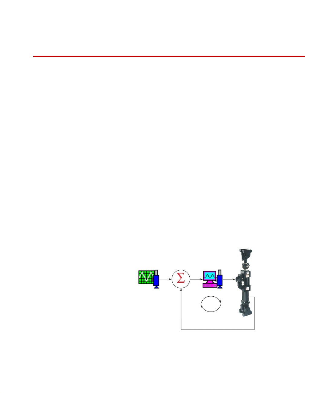
Simple Control diagram
When reduced to its basic
form, a Series 793 test
system typically includes
these elements. (The
command can also be
provided by the function
generator or MultiPurpose
TestWare).
Command
Source
Feedback
Source
Basic
TestWare
application
Summing and
Conditioning
Station
Manager
application
Controller Hardware
Controller Overview
MTS controllers equipped with Series 793 Software are referred to as MTS Series
793 Controllers.
Controller Overview
Types of MTS Series
793 Controllers
MTS offers several types of Series 793 Controllers. This manual pertains to the
following:
• MTS FlexTest Series 40/60/100/200 Controllers
• FlexTest GT Controllers
• FlexTest SE Controllers (Basic, Plus, and 2-Channel models)
• FlexTest IIm Controllers
For information about the hardware included in FlexTest GT, FlexTest SE, and
FlexTest IIm Controllers, see the MTS Models FlexTest IIm/GT/SE Controller
Hardware manual (PN 100-147-133). For more information on Series 494
controllers, see the MTS Models FlexTest®40/60/100/200 Controller Hardware
manual (PN 100-187-204).
Closed loop control MTS Series 793 Controllers provide closed-loop control of the mechanical and
hydraulic components of a test system.
MTS Series 793 Controller Overview Controller Hardware
19
Page 20

About MTS FlexTest Models 40/60/100/200
Types of MTS Series
793 Controllers
MTS offers several types of Series 793 Controllers. This manual pertains to the
following:
• MTS FlexTest Series 40/60/100/200 Controllers
• FlexTest GT Controllers
• FlexTest SE Controllers (Basic, Plus, and 2-Channel models)
• FlexTest IIm Controllers
Note For information about the hardware included in FlexTest GT, FlexTest
SE, and FlexTest IIm Controllers, see the MTS Series 793 Controller
Hardware manual (PN 100-147-133). For more information on Series
494 controllers, see the Series 494 Controller Hardware manual (PN
100-187-204).
About MTS FlexTest Models 40/60/100/200 Controllers
MTS FlexTest Models 40/60/100/200 Controllers are generally used in
servohydraulic test systems. They provide real-time closed-loop control, with
transducer conditioning and function generation to drive various types of servoactuators.
A FlexTest Controller consists of:
Controller capabilities
Controller Hardware
20
• One or more Series 494 Hardware chassis that contain controller hardware.
• A computer workstation that runs MTS controller applications.
PARAMETER FLEXTEST 40FLEXTEST 60FLEXTEST
100
Test Stations 2 Up to 6* Up to 8 Up to 8
Control Channels Up to 4 Up to 8 Up to 16 Up to 40
Conditioned
Transducer Inputs
Auxiliary Data Inputs Up to 16 Up to 32 Up to 64 Up to 96
*With On/Off Hydraulic Service Manifolds only
Up to 12 Up to 24 Up to 40 Up to 80
MTS Series 793 Controller Overview
FLEXTEST
200
Page 21
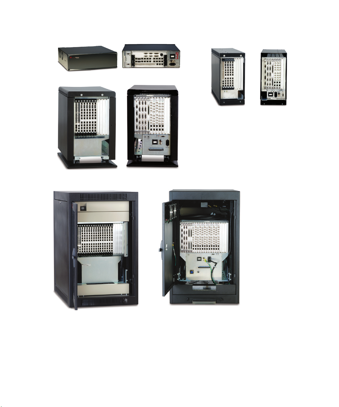
FlexTest 40 FlexTest 60
FlexTest 100
FlexTest 200
Front
(6 VME slots)
Back
(8 transition slots,
7 powered)
Back
(12 transition slots, 10 powered)
Back
(3 VME slots)
Front
(10 VME slots)
Front
(20 VME slots)
Back
(20 transition slots, 19 powered)
About MTS FlexTest Models 40/60/100/200
FlexTest Models 40/60/100/200 Controllers
MTS Series 793 Controller Overview Controller Hardware
21
Page 22
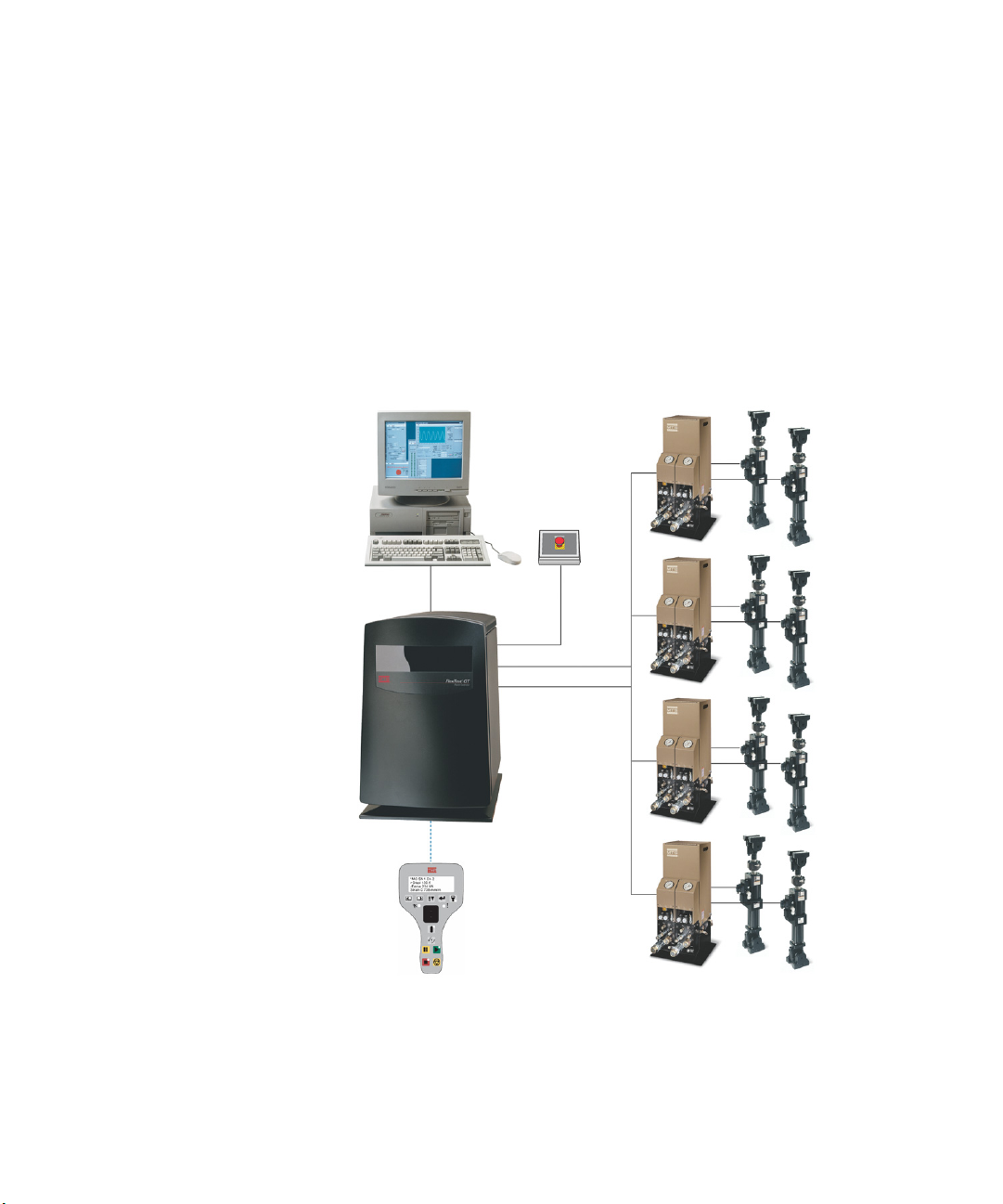
FlexTest GT Controller Description
Typical FlexTest GT
configuration
FlexTest GT Controllers
are typically used for
component or structural
testing applications.
FlexTest GT Controller Description
FlexTest GT Controllers are PC-based multi-station digital controllers consisting
of:
• A PC running Series793 Software
• A FlexTest GT Controller chassis equipped with Series 493 electronics
• An optional Handset
These components work together to control up to eight channels on up to four
independent stations.
Controller Hardware
22
MTS Series 793 Controller Overview
Page 23

FlexTest GT Controller Description
Typical FlexTest GT
configuration
About DUCs The Model 494.25 Digital Universal Conditioners (DUCs) condition AC and DC
The controller chassis is typically equipped with the following Series 493 Plug-In
Modules (32 maximum):
• One valve driver module per control channel (two-stage or three-stage)
• Two digital universal conditioners (DUCs) per control channel
• Hydraulic service manifold (HSM) and hydraulic power unit (HPU)
interlock modules
transducers. You can use the same DUC to condition an LVDT (AC transducer)
for one test, and then to condition a load cell (DC transducer) for another test.
Model 494.25 DUCs are full range conditioners. This means DUCs accurately
cover the full scale of the transducer, which eliminates the need to select between
ranges for transducers. DUCs also provide the resolution and repeatability
required for measuring small percentages of their total range.
MTS Series 793 Controller Overview Controller Hardware
23
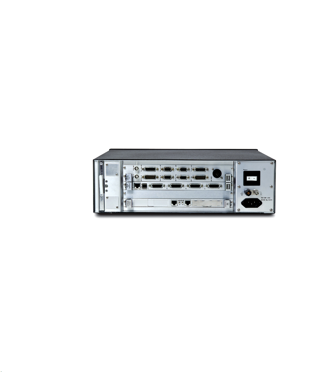
Page 24
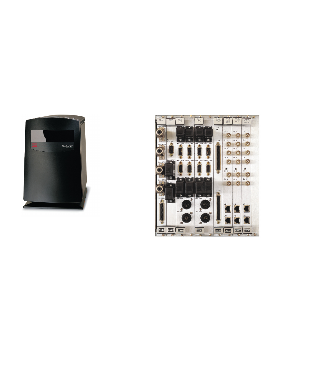
FlexTest GT Controller Description
FlexTest GT Controller
chassis
Controller
backpanel
Hardware options • Additional Model 494.25 DUCs
• Model 494.26 Dual DUC
• Model 494.21 Multi-Range DUC with Acceleration Compensation, which
• Auxiliary analog-to-digital (A/D) inputs
• Set of 16 digital inputs and 16 digital outputs for user-defined operation
• Encoders
provides conditioning and accelerometer compensation in a single card
Controller Hardware
24
MTS Series 793 Controller Overview
Page 25
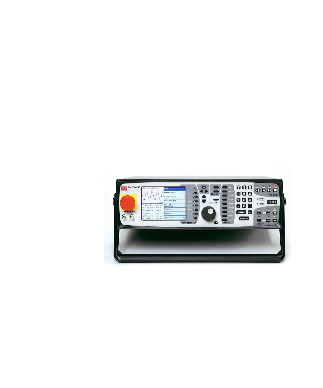
FlexTest SE Controller Description
FlexTest SE Controller
With the FlexTest SE Basic
model, you perform all
operations from the front
panel controls shown here.
For the FlexTest SE Plus and
FlexTest SE 2-Channel
models, you typically perform
most operations from a PC
loaded with Series 793
Software.
FlexTest SE Controller Description
The FlexTest SE Controller is a fully-digital PIDF controller that is available in
three configurations:
• FlexTest SE Basic
• FlexTest SE Plus
• FlexTest SE 2-Channel
FlexTest SE Basic The FlexTest SE Basic is a stand-alone controller equipped with a multicolor
display panel and direct-access menu keys. It does not require a PC to operate; a
special form of MTS Series 793 Software is stored directly on its internal flash
memory.
The FlexTest SE Basic Controller is equipped with its own manual (FlexTest SE
User Information and Software Reference, PN 100-149-574).
MTS Series 793 Controller Overview Controller Hardware
25
Page 26
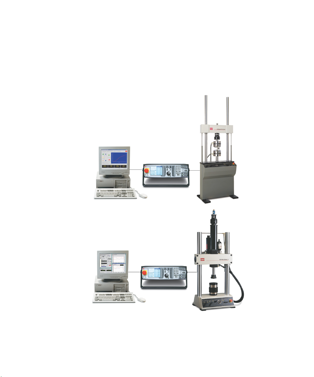
FlexTest SE Controller Description
FlexTest SE Plus
The FlexTest SE Plus
provides one control
channel, as shown in
this axial load unit
example.
FlexTest SE 2-Channel
The FlexTest SE 2-Channel
provides two control
channel, as shown in this
axial-torsional load unit
example.
Automated FlexTest
SE Controllers
The FlexTest SE is available in two automated configurations, the FlexTest SE
Plus and the FlexTest SE 2-Channel.
The FlexTest SE Plus and FlexTest SE 2-Channel Controllers include:
• A PC with Series 793 Software
• FlexTest SE Controller equipped with Series 493 Electronics
Controller Hardware
26
MTS Series 793 Controller Overview
Page 27

FlexTest SE Controller Description
Using Plus and 2-
Channel Controllers in
the Basic mode
Supplemental interface
for specimen handling
If desired, the FlexTest SE Plus and FlexTest SE 2-Channel Controllers can also
be used without PCs (in the FlexTest Basic configuration). The Controller is fully
capable of system control without the PC.
For FlexTest SE Plus and FlexTest SE 2-Channel controllers you typically use:
• The FlexTest SE front panel controls to facilitate specimen loading
• The Station Manager application running on the PC as the primary test
interface
You can position the FlexTest SE Controller near your load frame or test fixture
with an adjustable arm or a portable test stand. This eliminates the need for a
Remote Station Controller (RSC).
MTS Series 793 Controller Overview Controller Hardware
27
Page 28
FlexTest SE Controller Description
The FlexTest Controller
manages specimen
installation. You use the
FlexTest SE Controller to
position the actuator when
loading specimens.
The PC manages
testing. You use a PC
loaded with Series 793
Software to design and
run tests.
Booting the controller in the automated mode disables several of the menus on
the front panel of the controller. These menus are used for testing in nonautomated FlexTest SE Basic models. To compensate for the disabled front-panel
menus, you use the Station Manager application interface on the PC to set up and
run tests.
Controller Hardware
28
MTS Series 793 Controller Overview
Page 29
FlexTest SE Controller Description
FlexTest SE
Controller backpanel
Typical FlexTest SE
Plus configuration
Options • Up to three additional DUCs
FlexTest SE Plus Controllers typically support one channel on one station, and
include the following:
• VME processor capable of an update rate of 6kHz, along with a two-stage or
three-stage valve driver, and two digital universal conditioners
• One analog input and three analog outputs
• Digital inputs and outputs (for interlocks or user-defined purposes)
• Serial interface for temperature control
• Six auxiliary analog-to-digital input channels
• Test stand (adjustable arm or portable stand) for the FlexTest SE Controller
Typical FlexTest SE 2-
Channel configuration
For more information For more information on DUCs, see “About DUCs” on page 23.
MTS Series 793 Controller Overview Controller Hardware
The FlexTest SE 2-Channel Controller is designed for two-channel, singlestation test applications. FlexTest 2-Channel Controllers include the following
additions to the FlexTest SE Plus configuration:
• Two two-stage or three-stage valve drivers
• Four digital universal conditioners (DUCs)
29
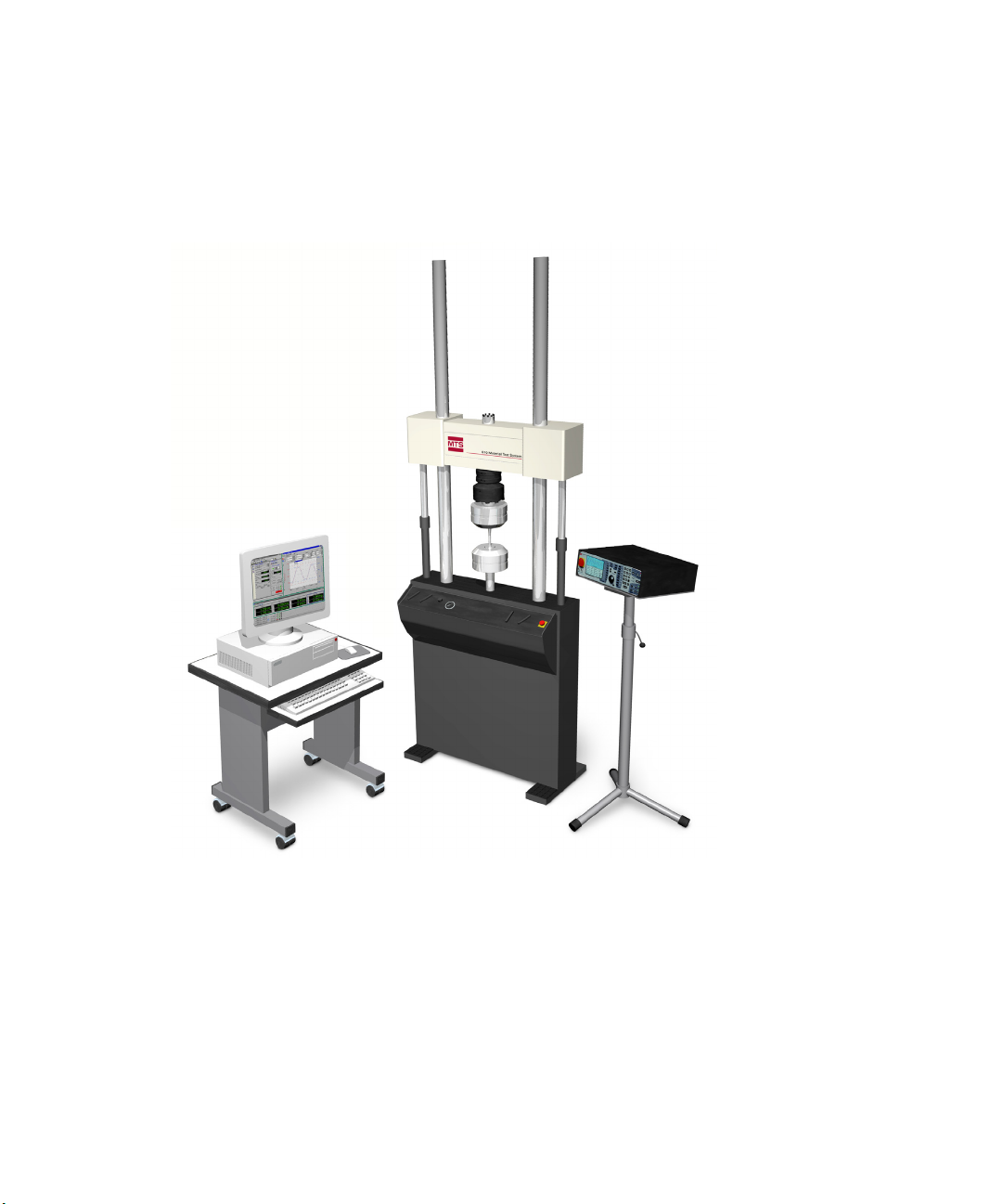
Page 30
FlexTest IIm Controller Description
Typical FlexTest IIm configuration
FlexTest IIm Controllers are typically used for
component or structural testing applications
that require higher channel counts.
FlexTest IIm Controller Description
FlexTest IIm Controllers are PC-based multistation digital controllers consisting
of two major hardware components:
• A PC running Series 793 Software
• A FlexTest IIm Controller chassis, equipped with Series 497 Electronics
FlexTest IIm Controllers support up to sixteen control channels on up to four
independent stations.
Controller Hardware
30
MTS Series 793 Controller Overview
Page 31

FlexTest IIm Controller Description
Per channel resources
-One valve driver output
-One D/A output
-One A/D input
-One AC conditioned input
-Two DC conditioned inputs
FlexTest IIm Console Each FlexTest IIm console houses the following rack-mount components:
• 497.01 Analog Chassis equipped with a complement of Series 497 valve
drivers and conditioners, supporting up to 16 channels of control
• 497.05 Hydraulic Control Panel, which controls at least one Hydraulic
Power Unit (HPU) or actuator manifold
• 498.22 Test Processor Chassis
• 16 inputs and 16 outputs of user DIO
The FlexTest IIm Controller is available in a full-bay (vertical) console, a tabletop console, or a roll-around console.
MTS Series 793 Controller Overview Controller Hardware
31
Page 32

Controller Hardware Options
Controller Hardware Options
Remote Setpoint
Adjust (RSA)
The Remote Setpoint Adjust control allows you to use one or more encoders on a
station to control the setpoints of control channels (available for FlexTest IIm and
FlexTest GT Controllers only).
Model 494.05 Handset The Handset provides a portable control interface for performing basic test
operations such as:
• Moving the actuator to install the specimen
• Monitoring sensors
• Zeroing sensors
• Resetting and overriding interlocks
• Applying and removing hydraulic pressure from the station
• Starting and stopping tests
The Handset is lightweight and can be placed on a table or mounted on a stand in
close proximity to the test frame to facilitate specimen loading.
Password protection The test designer can enable Handset operation at any access level. Access is set
on the Handset Options page in the Station Options window of the 793 Station
Manager application.
Other features • The Handset can be configured to operate only in the displacement control
mode.
Controller Hardware
32
• The manual command control auto-disables after 90 seconds to minimize
inadvertent operation.
MTS Series 793 Controller Overview
Page 33

Controller Hardware Options
Thumbwheel. Manually
positions the actuator when
Manual Command is enabled
Programmable Display.
Shows sensor output and
the current control mode.
You can use it to zero
sensors and change
control modes.
Interlock Indicators
Hydraulics Off
Model 494.05 Handset
*MC SN1 Ch1
>Displ 130.5
-Force 200 kN
Hydraulics Indicator
Exclusive Control
Interlock Reset/Override
Program Run/Stop/
Hold Controls
Manual Command
MTS Series 793 Controller Overview Controller Hardware
33
Page 34

About TEDS Sensors
About TEDS Sensors
Note Only controllers that use Series 494 Hardware support the use of MTS
TEDS (transducer electronic data sheet) sensors.
TEDS sensors have built-in memory chips that store basic TEDS information
(manufacturer, model, number, and serial number).
When you connect an initialized TEDS device to a conditioner, the Station
Manager application reads the basic TEDS information from the device, and a
sensor assignment window appears.
The sensor file list in this window only lists sensor files that match the basic
TEDS information, conditioner type, and dimension. The sensor assignment
window contains the same sensor assignment list found in the Station Setup
window.
Controller Hardware
34
TEDS devices Available TEDS devices include:
• MTS sensors that include basic TEDS information saved in an integral
TEDS chip that is built into the sensor.
• MTS TEDS Transducer ID modules that include a chip that stores basic
TEDS information for a specific sensor. The TEDS module connects to the
sensor.
MTS Series 793 Controller Overview
Page 35

Chapter 3
Controller Software
This section contains descriptions of the software included with MTS 793
Controllers. Regardless of the differences in hardware between one controller
and another, all MTS 793 Controllers are equipped with MTS 793 Software.
Model 793.00 System Software Bundle
Multitasking Windows
environment
MTS 793 Software runs on the Windows operating system, which is
multitasking. This means you can run more than one 793 application at a time.
For instance, you can design a test configuration at the same time you are running
a test. Also, while running a test, you can adjust control parameters in response to
test events.
Model 793.00 System Software Bundle
All MTS Series 793 Controllers are equipped with the Model 793.00 System
Software bundle. The System Software bundle contains applications that perform
activities centered around maintaining servo control of a test station. These
applications include the following:
• Project Manager
• Station Builder
• Station Manager
• Basic TestWare
• Station Desktop Organizer
• Hwi File Editor
• Controller Management Tool (FlexTest SE Controllers only)
MTS also offers optional control and application software.
Project Manager A test data management application that allows you to create and configure
Series 793 Projects, start Series 793 applications, and edit System Settings.
Projects make data organization easy. You can configure Series 793 Projects to
organize data around specific tests, users, applications, or stations.
MTS Series 793 Controller Overview Controller Software
35
Page 36

Model 793.00 System Software Bundle
Station Builder A station design application that allows you to allocate controller resources, such
as valve drivers, conditioners, digital inputs, and so forth, to station configuration
files. You define parameters for the resources in the station configuration with the
Station Manager application. This application is password protected.
Station Manager A sophisticated controller application whose primary function is to maintain
station servocontrol while allowing you to perform typical test operations, such
as:
• Creating parameter sets that define and optimize the operational
characteristics, such as sensor ranges and conditioner gains, of the station
resources in your station configuration files
• Monitoring the various analog and digital signals sent to and from your
controller
• Monitoring station interlocks and controlling hydraulic or
electromechanical station power
• Managing tests with run, hold, and stop controls
Basic TestWare A test design application that allows you to create monotonic and cyclic tests and
to acquire data.
Management Tool
Controller Software
36
Station Desktop
Organizer
A software utility that allows you to manage the windows and displays
associated with Series 793 Software. This utility is useful for reducing screen
clutter when you work with multiple stations simultaneously.
Hwi File Editor A software utility that allows you to create and edit hardware interface (.hwi)
files. Hwi files are text files that define the internal components—or resources—
available to MTS Series 793 Controllers. Resource examples include
conditioners, valve drivers, digital inputs, and so forth. The text description of a
resource in an .hwi file includes proximity information, such as the location of
the slot in the chassis in which the resource is installed, and the rear-panel
connectors through which it can be accessed.
Controller
A software utility that allows you to perform a variety of maintenance activities
on FlexTest SE Controllers, including updating the executable software stored on
the controller flash-disk, installing and backing up user files, and assigning
various controller attributes, such as regional settings, passwords, and multi
controller setup.
Note The Controller Management Tool pertains to FlexTest SEs only.
MTS Series 793 Controller Overview
Page 37

Software Options Available with Key Codes
For more information For more information about using Station Manager to assign parameters to
station configurations, see “About Assigning Parameters to Station
Configurations” on page 54.
For more information about using Basic TestWare to create test designs, see
“Designing Tests with the Basic TestWare Application” on page 65.
For more information about using Station Manager to execute tests, see “About
Running Tests” on page 76.
Software Options Available with Key Codes
Your Series 793 Controller may be equipped with optional software that aids or
enhances station servo control. These features are available as keyed options on
the standard Series 793 System Software installation CD.
Model 793.02
Calculations
Model 793.03
Calculations with
Outputs
The Model 793.02 Calculations option allows you to assign a calculated analog
input for control feedback or data acquisition. Calculated input values are
determined by applying a user-defined mathematical equation to the specified
signal values. You assign mathematical functions with an integrated equation
editor.
You use the Station Builder application to assign calculated input resources to
control modes, stabilization feedback, external command inputs, and auxiliary
inputs.
The Station Manager application creates calculated input channels from input
resources that are mapped to calculated input resources.
The Model 793.03 Calculations with Outputs option provides an output signal
with which you can drive a hardware resource (for example, a valve driver). Each
calculated output signal specified in the Station Builder application is defined by
an equation created in the Station Manager application.
You can also assign a control channel to a virtual output resource to create a
“virtual channel.” The output of a calculated channel is not defined by an
equation or assigned to hardware. Its output is used by a calculated output
resource that can be used to drive hardware such as a servovalve.
MTS Series 793 Controller Overview Controller Software
37
Page 38

Software Options Available with Key Codes
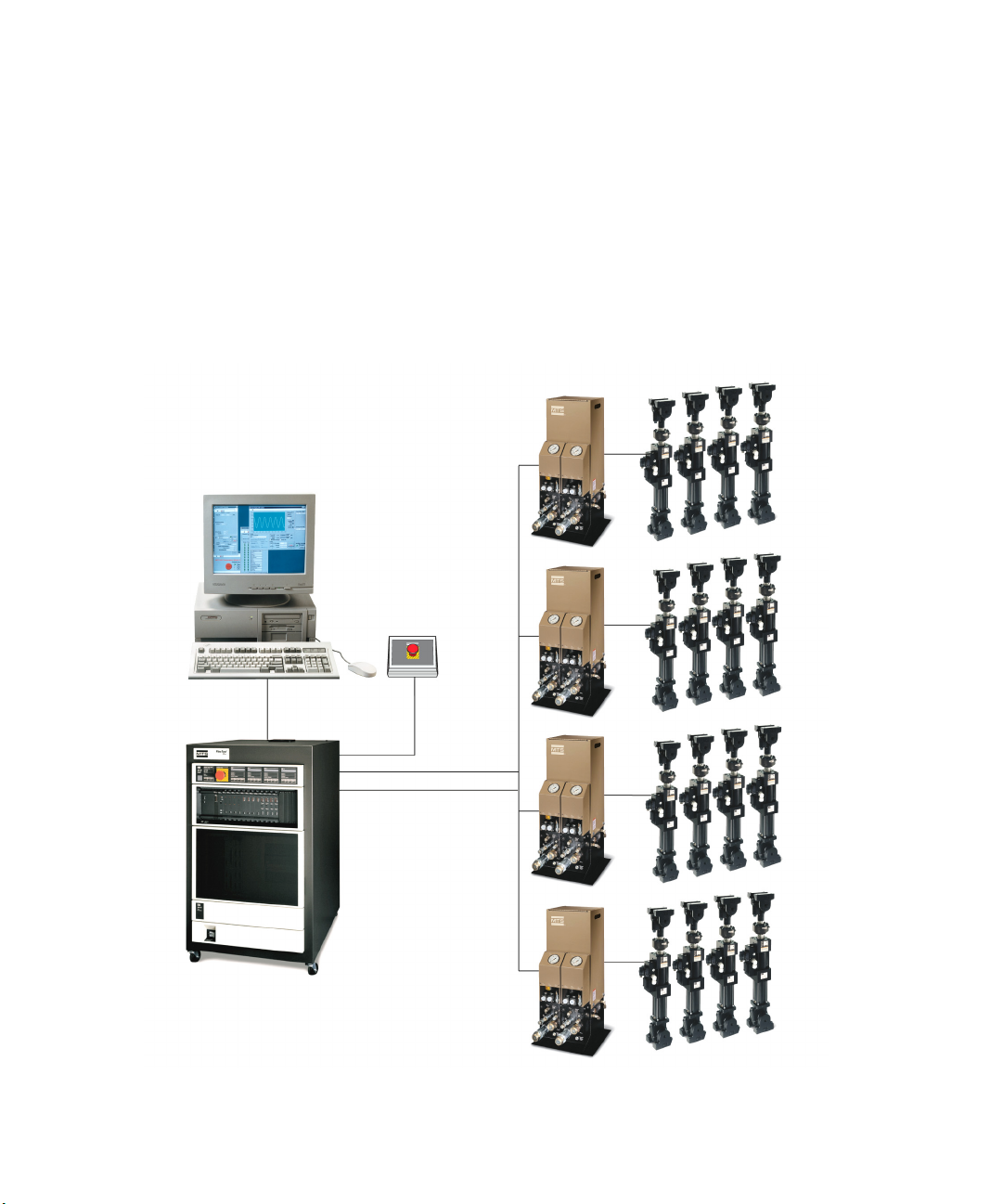
The PC-Per-Station kit
allows each test station to
have its own PC. (Test
stations are equipped with
separate hydraulic service
manifolds.)
Model 793.04 PC-Per-
Station Kit
The PC-Per-Station Kit allows you to use up to four PCs with your FlexTest IIm,
or FlexTest GT Controller. Multiple PCs linked to a single controller allows
different operators to run their assigned stations without having to share PCs. It
also decreases downtime since multiple operators can run different tests
simultaneously (at their assigned stations) through a single controller.
Model 793.05/.06/.07/
.08/.18 Compensators
Controller Software
38
Compensators compare your command with the corresponding sensor feedback
to ensure that the command is fully applied to the specimen. If the sensor
feedback indicates the specimen is not reaching the commanded levels, the
compensator alters the command until the desired result is achieved.
MTS Series 793 Controller Overview
Page 39

Software Options Available with Key Codes
Each type of compensator uses a different technique to achieve the commanded
levels. Certain compensators work more effectively than others for specific
applications. The following compensators are available as Series 793 Software
options:
• Model 793.05 Amplitude Phase Control (APC) Compensator
• Model 793.06 Adaptive Inverse Control (AIC) Compensator
• Model 793.07 Arbitrary End-level Control (ALC) Compensator
• Model 793.08 Peak Valley Phase Control (PVP) Compensator
• Model 793.18 Adaptive Harmonic Cancellation (AHC)
Model 793.10
MultiPurpose TestWare
(MPT)
Model 793.11
Profile Editor
Model 793.12
Trend Monitoring
A sophisticated general purpose test design application that allows you to build
test procedures by defining and linking modular test activities (called processes)
together in a “drag and drop” environment. You can also assign serial or parallel
trigger relationships between processes to accommodate conditional test events.
MPT allows you to link function generation, data acquisition, event, and trigger
elements to quickly build virtually any test procedure.
MPT is required to execute many Series 793 niche-specific applications, as noted
in the application descriptions that follow.
For specific instructions about using MPT, see the MultiPurpose TestWare
Application Software manual (PN 100147131).
Note MultiPurpose TestWare is standard with FlexTest IIm systems.
A stand-alone waveform design application that allows you to create arbitrary
waveforms (referred to as profiles). You can create block arbitrary and phase
profiles, and analyze the waveforms with the graphical preview feature. Once
created, you play out the profiles with the MultiPurpose TestWare application,
using the Profile process.
A specialized analysis application that allows you to monitor trend data that has
been recorded in real time. This application works with the MultiPurpose
TestWare application, using the Trend process.
MTS Series 793 Controller Overview Controller Software
39
Page 40

Software Options Available with Key Codes
Model 793.14
Fatigue Monitoring
Model 793.15
Degree of Freedom
Control (DOF)
Model 793.16
Three Variable Control
(TVC)
Model 793.21 Cascade
Control
A specialized analysis application that allows you to monitor fatigue data that has
been recorded in real time. This application works with the MultiPurpose
TestWare application, using the Fatigue process.
DOF control (available with Series 793 Software version 4.0 and later) provides
a coordinate system in which actuators act in groups to produce movement in six
degrees of freedom (vertical, longitudinal, lateral, roll, pitch, yaw). The feedback
and command are converted from actuator coordinates at the start and finish of
the control loop. Specifically, the raw actuator feedback signals are converted to
DOF coordinates. The controller then closes the loop using these DOF
coordinates. The DOF controller outputs are then combined to provide individual
actuator valve commands.
TVC control (available with Series 793 Software version 4.0 and later) provides
simultaneous control of displacement, velocity, and acceleration variables. It
combines the command and feedback signals of all three control variables to
provide the needed system performance, emphasizing displacement at low
frequencies, velocity at middle frequencies, and acceleration at high frequencies.
This tailors the frequency stability characteristics of the wave generator to
achieve the best performance across the spectrum.
The Model 793.21 Cascade control mode is typically used for testing that
requires a high degree of stability under dynamic conditions.
Model 793.23 MPT
Controller Software
40
Variables
This control mode uses two control loops. The output of the outer control loop is
used as the input to the inner control loop, as if it were the final control element.
The Model 793.23 MPT Variables feature provides test designers with the
capability to define test parameter variables. With this feature, test designers can
create tests in which the operator enters test parameter variables in just one place.
When this is done, all related variables in the test are updated automatically
without the operator having to open each associated process individually. This
can significantly reduce test design and setup time and reduce setup errors.
This feature includes an MPT Calculation process that allows test designers to
add mathematical operators to variable parameters.
Another process, Set Controller Value, allows you to set values for the
calculation parameter and calculation variable values defined in the station
configuration. When the process is triggered, the values set in this process
override their associated values inc the station configuration.
MTS Series 793 Controller Overview
Page 41

Software Options Available with Key Codes
Model 793.25 CAN Bus
Support
Model 793.26 Signal
Based Command
Model 793.71 Time
History Playout (THP)
Model 793.72 Time
History Playout with
Data Acquisition (THD)
The Model 793.25 CAN Bus feature supports CAN bus devices. CAN bus is a
computer network protocol and bus standard that allows devices to communicate
with each other without a host computer. You can use CAN Bus resources in
control loops and event-action sequences.
The Model 793.26 Signal Based Command process allows you to generate
command based on signal values specified in a predefined lookup table. The
lookup table is contained in a tab-delimited text file which defines the
relationship between command and signal values.
An MPT process that allows you to drive a test system equipped with an MTS
Remote Parameter Control (RPC) time history file.
An MPT process that allows you to acquire and digitize analog test response data
in the MTS RPC III file format and floating point time history files. RPC analysis
software allows you to calculate the system transfer function of the system with
the digitized file.
Model 793 Multibox
Option
Model 793.100/101
Hybrid Simulation
The Model 793 Multibox Option allows the use of networked chassis to provide
additional hardware resources.
The Model 793.100 Hybrid Simulation (Internal Model) and Model 793.101
Hybrid Simulation (External Model) options allow 793 software and hardware to
interface with simulation models.
For more information For more irnformation about compensators, see “About Compensators” on page
59.
For more information about creating test procedures with MPT, see “About
Running Tests” on page 76.
MTS Series 793 Controller Overview Controller Software
41
Page 42

Software Options Available on Separate Media
Software Options Available on Separate Media
MTS has additional application software designed for use with Series 793
Controllers, and is continually developing more. These applications are not
available as keyed options on the standard Series 793 System Software
installation CD; they are distributed on separate media. The following
descriptions are just a few examples of optional Series 793 applications (contact
MTS for a complete list).
Model 793.20 High-
Cycle, Low-Cycle, and
Advanced Low Cycle
Fatigue
Model 793.31 Dynamic
Characterization
Model 793.33 Static
Deflection
Model 793.40 Fatigue
Crack Growth
An MPT process that allows you to define, execute, and analyze constant
amplitude, high-cycle and low-cycle fatigue tests. This software offers predefined
test templates to facilitate the execution of ASTM E606 Room Temperature
trapezoidal wave shape LCF, and E466 HCF test standards. It provides real-time
display of hysteresis loops and a variety of other plots to let you monitor and
record the progress of your test. It also supports transition from LCF to load
controlled HCF testing so you can collect critical LCF test information, then
quickly run your test to failure, maximizing your test throughput.
An MPT process that allows you to characterize the dynamic properties of
elastomeric materials and components. You can sweep temperature, frequency,
dynamic amplitude, mean level, and phase between multiple control channels
simultaneously. It also allows you to nest sweeps.
An MPT process that allows you to characterize the static deflection properties of
elastomeric materials and components. You load the specimen between
predefined load or displacement end levels and acquires subsequent timed data.
Then this software calculates the stiffness of the sample as a cord or tangent
modulus during the loading or unloading portion of the test, or as an average of
the two. Finally, the process compares the calculated stiffness to predefined
limits. It can also compare individual load and displacement data pairs to
predefined envelopes for quality control applications.
An MPT process that allows you to quickly set up and run tests to accurately
measure the crack growth rate of materials. It includes several powerful
capabilities, such as delta K control, as well as compliance and visual
measurement of crack length. With the visual method this software allows you to
hold the test, make the measurement, change parameters, and resume the test. This
software includes a predefined test template for fast, accurate execution of ASTM
E647-91 fatigue crack growth rate tests. It provides real-time analysis of crack
length versus cycles, and da/dN versus delta K. It can be configured to run delta K
controlled and constant Kmax controlled crack propagation tests to obtain the
material response for the specific conditions of interest.
Controller Software
42
MTS Series 793 Controller Overview
Page 43

Chapter 4
Setting Up A Project
To start a testing session, you create (or select) a place to keep the files you will
be generating while testing, such as test design files and test data files. This place
is referred to as a “Project.”
Project
Manager
application
Project 1 Project 2 Project 3
Creating a Station Configuration
Next, you use the Station Builder application to allocate resources from your
Hardware interface file to create individual Station Configuration files.
Station
Builder
application
Hardware
Interface
file
Station Config
file 1
Station
Config file 2
Station
Config file 3
hwi
Operation Concepts
This section provides conceptual information about using 793 Software
components to perform specific test activities.
Operational Overview
The following pages provide a high-level overview of the steps required to set
up, design, and run a test.
Operational Overview
MTS Series 793 Controller Overview Operation Concepts
43
Page 44

Operational Overview
Assigning Parameters to the Station Configuration
Station
Manager
application
Station
Config
file
Parameter
set 1
Parameter
set 2
Parameter
set 3
Next, you load a station by selecting a Station Configuration file with the Station Manager application.
You assign parameters of the resources in Station Configuration file to optimize performance according
to your test requirements.
PARM PARM PARM
Creating a Test Design
Station
Manager
application
Station Config
file with
Parameter set
MultiPurpose
TestWare
application
Test
Procedure
file 1
Test
Procedure
file 2
Test
Procedure
file 3
Next, you create a test program. To do this, you select your Station Configuration file and desired
parameter set with the Station Manager application. Then from the Station Manager application, you
select the desired test design application, such as Basic TestWare or MPT, and create test design files.
PARM
Running a Test
Station
Manager
application
Station Config
file with
Parameter set
MultiPurpose
TestWare
application
Tes t
Procedure
file
Test Data
file
Finally, with all of the files open, you start the test from the Station Control panel of the Station Manager
application. Test Data files are generated according to the type of test design application you used to
create your test design file.
PAR M
44
Operation Concepts
MTS Series 793 Controller Overview
Page 45

Operational Overview
For more information For more information on creating a station configuration, see “About Station
Configurations” on page 51.
For more information on assigning parameters to the station configuration, see
“About Assigning Parameters to Station Configurations” on page 54.
For more information on creating a test design, see “About Test Designs” on
page 64.
For more information on running a test, see “About Running Tests” on page 76.
MTS Series 793 Controller Overview Operation Concepts
45
Page 46

About Projects
Project folders contain various
files centered around test
design and test execution.
Projects also contain settings
that include references to
common support file stored
elsewhere (as shown to the
right). Project folders are
displayed with a double-red line
notation.
Project 1
Station
Config files
Calibration
files
MPT Test
Procedure file
templates
Project 2
Project 3
Files referenced in Projects
scf
Project folder icon
Project folders contain
predefined subfolders.
About Projects
Understanding Projects
A Series 793 Project folder (or Project for simplicity) contains the various types
of information you typically acquire while testing.
Operation Concepts
46
Projects are displayed on your system as modified folder icons, as shown to the
left. Each Project folder contains a collection of information related to testing.
The information is organized into predefined subfolders, as shown in the
expanded Sample Project below.
MTS Series 793 Controller Overview
Page 47

Understanding Projects
Projects include information:
• Required to perform tests, such as configuration files and test design files;
and
• Generated by testing, such as test data, scope images, and specimen files.
• Captured as a result of unexpected shutdowns (Shutdown Recorder
directory)
Benefits of Projects The Project Manager (and the ability to create Projects) became available in
version 4.0 of Series 793 System Software. Projects offer the following benefits:
• Projects separate user information from system and controller information.
This eliminates confusion about where your test files are stored, and allows
you to set file access privileges for individual users.
• Projects allow different users to keep the information in their projects
separate from one another.
• Projects allow you to use standard Windows features to add security to,
duplicate, and archive the information stored in them.
• Projects are configurable, allowing you to match your Project with your test
environment.
Your initial Project The Series 793 Installation Wizard automatically creates an initial Project (with
the default name of Project1), and gives you the option of assigning it as the
default Project.
Note If you have never used Project Manager to assign a default Project but
one is assigned (you are not prompted to select a Project when starting
Series 793 applications), this option was probably selected during
installation.
Upgrade installations For upgrade installations, you have the option of copying all of your existing test
design and test data files from their original locations to the initial Project (the
files are copied, not moved, so the original files will remain in their original
locations).
For more information For more information on how projects separate user information from system and
controller information, see “About Project Information” on page 85.
MTS Series 793 Controller Overview Operation Concepts
47
Page 48

Using Project Manager to Modify Projects
Default Projects.
You can use the Project
Manager application to
assign a default Project.
Default Projects open
automatically when you
start Series 793
applications.
Project
Manager
application
Project 1
Project 2
Project 3 set as the
default Project.
Default Projects are
displayed with a
checkmark notation.
Using Project Manager to Modify Projects
Every Project contains a Project Settings file. Most Project settings are folder
path specifications. To configure Projects, you use the Project Manager
application to edit the Project Settings file. A Project Settings file acts like a
switchboard that directs the flow of information within a Project.
The Project Manager also allows you perform other tasks, such as editing system
wide settings and starting Series 793 applications, but its primary function is to
configure Projects.
When you set up and configure projects with Project Manager you are not
required to apply power to your station or handle station hardware—you are
simply creating files.
Operation Concepts
48
You can configure Projects in a variety of ways to suit your specific needs. For
instance:
• You could set up one Project to acquire all of the test data generated by a
• You could set up another Project to acquire all of the test data generated by
Projects make this type of data organization easy. You can configure Projects to
organize data around specific tests, users, applications, or stations. A Project is a
custom portal to your test system.
specific operator (example: “Ken’s Project”).
multiple operators from a specific specimen (example, “Shock Absorber
Project”).
MTS Series 793 Controller Overview
Page 49

About Hardware Interface Files
Hardware
Interface
file
hwi
The Hardware Interface file represents all of the hardware resources available to
your test system.
Understanding Hardware Interface Files
The resources in your Station Builder application resource lists are defined by the
hardware interface file (or .hwi file) installed with your system software.
Resource examples include conditioners, valve drivers, digital inputs, and so
forth. The .hwi file defines what internal components are available to your
controller, which controller slots they are installed in, and which rear-panel
connectors they are accessed through.
About Hardware Interface Files
Hardware interface file
syntax
.hwi file and the
Station Builder
application
Hardware interface files (.hwi) are text files. The text description of a resource in
an .hwi file includes proximity information, such as the location of the slot in the
chassis in which the resource is installed, and the rear-panel connectors through
which it can be accessed. The text in hardware interface files uses precise syntax
which must be followed when editing the text directly.
You use the Station Builder application (one of the applications included with
MTS 793.00 System Software) to define test stations by allocating some or all of
the resources listed in the .hwi file.
Initial .hwi file The .hwi file associated with a given controller is typically created at MTS
according to the resources included with the controller. It may be necessary to
MTS Series 793 Controller Overview Operation Concepts
edit this file if system resources are added, removed, or repositioned in the
controller chassis.
49
Page 50

Understanding Hardware Interface Files
Editing .hwi files with
the Hwi File Editor
MTS has a software utility for editing .hwi files, called the Hwi File Editor. This
utility minimizes the chance of introducing syntax errors when making changes
to existing .hwi files or creating new .hwi files.
The built-in logic of the Hwi File Editor streamlines the process of adding new
resources. For instance, when you add or remove analog resources from an .hwi
file, the .hwi file Editor has a fill down function that automatically assigns proper
channel numbers and resource names.
If you add new hardware to your system because of a need for additional
conditioning, you can use the Hwi File Editor to reflect those changes in your
system .hwi file.
In addition to the Hwi File Editor, you can create or edit .hwi files with any text
editor, such as Microsoft Notepad.
Operation Concepts
50
MTS Series 793 Controller Overview
Page 51

About Station Configurations
A Station Config file can represent only a portion of the total
resources available in the Hardware Interface file.
hwi
Station
Config file
Hardware
Interface
file
Station
Config
file
Station
Builder
application
About the Station Builder Application
The Station Builder application defines the parts of a station configuration from a
pool of system resources listed in the hardware interface file. With the Station
Builder application, you can allocate all or a portion of your system resources to
create station configuration files.
About Station Configurations
Initial station
configuration
MTS typically installs Series 793 Software for you and supplies your controller
with a station configuration. You use the Station Builder application to modify
your initial station configuration when replacing or adding resources.
MTS Series 793 Controller Overview Operation Concepts
51
Page 52

Using the Station Builder Application to Create
Using the Station Builder Application to Create Station Configurations
When you create station configurations with the Station Builder application, you
are not required to apply power to your station or handle station hardware--you
are simply creating files.
To create a station configuration, you allocate controller resources such as valve
drivers, conditioners, analog I/O, digital I/O, and hydraulic control resources to
create the following:
• Channels—used to control an independent quantity, such as force or
displacement, on the test fixture.
• Auxiliary Inputs—used to monitor signals for data acquisition or display. As
an option, you can create a calculated input resource for auxiliary inputs.
• Readouts—used to send analog signals to external readout devices such as
oscilloscopes and meters.
• Digital Inputs—used to receive digital logic signals from external devices.
As an option, you can create a calculated input resource for digital inputs.
• Digital Outputs—used to send digital logic signals to external devices. As
an option, you can allocate a resource for “virtual” digital outputs not tied to
hardware, but available for use in other calculations.
Where station
configurations are
Operation Concepts
52
stored
• Calculated Analog Outputs—this option is used to apply user-defined,
algebraic formulas to selected output signal values to generate new,
calculated output signal values.
• Calculated Analog Inputs—this option is used with calculated resources to
apply user-defined, algebraic formulas to selected input signal values to
generate new, calculated input signal values.
• Remote Setpoints—used to set up the Remote Setpoint Adjust (RSA)
controls (optional, stand-alone hardware controls used to control actuator
setpoints).
Once you have allocated the resources you need, you can save your configuration
file (it acquires a “.cfg” extension).
By default, configuration files are located at C:\MTS 793\Controllers\Controller
Name (for example, FlexTest GT)\Config. Configuration files are referenced
from the Project you selected when you started the Station Builder application.
(You can change where your station configurations are saved by changing your
Project settings with the Project Manager application.)
MTS Series 793 Controller Overview
Page 53

Station Builder Application Window
Station Builder application main window
Menu bar
To ol b ar
Tree view of
station
resources
Lists of
system
resources
The Station Builder application has one main window that enables you to create
station configurations.
Station Builder Application Window
MTS Series 793 Controller Overview Operation Concepts
53
Page 54

About Assigning Parameters to Station
Creating parameter sets. You use the Station Manager application to create Parameter
sets. Parameter sets define the operation characteristics of the resources in the selected
Station Config file. You can create up to 15 parameter sets for a Station Configuration.
Station
Manager
application
Station
Config
file
Parameter
set 1
Parameter
set 2
Parameter
set 3
Selecting Parameter sets. When you start the
Station Manager application, you select a Station
Config file, and then you select the desired
parameter set for the Station Config file.
Station Config
file paired with a
parameter set.
PARM
PARM
PARM
PARM
PARM PARM PARM
About Assigning Parameters to Station Configurations
About Parameter Sets
In the pretest phase, you use the Station Manager application to optimize how the
parts of your system work together. A product of the pretest phase is a parameter
set that you save with the station configuration.
A parameter set adapts the way the resources in your station configuration
operate to suit your test requirements. Parameters include everything from tuning
values to detector settings. When you change these settings from their default
values, you create a unique parameter set for the station configuration.
54
Operation Concepts
MTS Series 793 Controller Overview
Page 55

Using the Station Manager Application to Create
Using the Station Manager Application to Create Parameter Sets
When you optimize your station configuration with the Station Manager
application, you perform many of the activities required to perform a test: You
apply power to the station, manually position the actuator, apply tuning
programs, monitor waveforms, and so forth. While doing these activities you
adjust parameter values accordingly, which you save with your station
configuration.
You typically perform the following activities to optimize a station configuration
while creating a parameter set.
Creating sensor files To begin creating a parameter set, you typically:
• Create and assign calibration files for sensors with on-board conditioning
• Adjust conditioner values for sensors with external conditioning
Balancing the
servovalve
For optimal system performance, you should check and adjust the servovalve
before performing tests.
Balancing the servovalve is the process of optimizing communication between
the valve driver and servovalve. During installation, your servovalve is typically
balanced at its midstroke position. The signal values in your parameter set reflect
that initial procedure. For optimal performance, you should balance the
servovalve again after you position the actuator to the test start position.
Adjusting dither You may also need to adjust dither. Dither is a low-amplitude, high-frequency
sine wave that the controller applies to the servovalve spool. Dither keeps the
spool in motion so it operates smoothly and doesn’t stick to its cylinder walls. It
is especially useful for tests that use small amplitude commands.
Setting detectors Before installing the specimen, you should set detector limits and actions to
minimize the risk of injury to yourself and damage to your specimen. After you
install the specimen, you adjust your detectors to accommodate your test design.
Tuning control modes You need to install the specimen before you adjust force tuning because force
turning involves every element of the force-train, and requires closed-loop
control.
MTS Series 793 Controller Overview Operation Concepts
55
Page 56

Using the Station Manager Application to Create
To complete this task, make sure the force tuning values established in your
parameter set are suitable for the test you are about to run. To do this, you
typically:
• Create and apply a simple tuning program with the function generator
• Evaluate the current force tuning values by comparing command and
feedback signals
• Make Proportional (P) gain and Integral (I) gain adjustments to achieve
optimal force tuning
Displacement tuning values typically do not require frequent adjustment.
Optimal force tuning values, however, are a function of specimen compliance,
which tends to change over time, or even from test to test. Because of this, it is
good practice to tune the force control mode often. You should also tune the force
control mode whenever you make any change to the force train, such as changing
gripping fixtures.
Verifying calibration
adjustments
You can verify the calibration of your force sensor (load cell) by performing a
shunt calibration. It is good practice to perform a shunt calibration before you
begin a test to ensure accurate test data.
After your force sensor is calibrated for the first time (or when it is fully
recalibrated), someone will perform a shunt calibration to create a reference
value that will be stored in the calibration file of the force sensor.
You periodically compare this reference value with the values you obtain when
performing subsequent shunt calibrations. This validates the current state of
calibration of the force sensor.
Saving station views To avoid reopening windows and displays each time you reopen a station
configuration, you save the desktop layout as a station view. When you restore a
saved view, the windows reposition automatically.
Each time the Station Manager application closes, it saves the current station
view as the default view. When you reopen the station it appears with the
windows repositioned as they were when the station was last closed. This allows
you to revert to the last saved station view.
You can also restore a default view by selecting Restore Default View. This
function repositions the station windows to where they were the last time the
station was closed.
Operation Concepts
56
MTS Series 793 Controller Overview
Page 57

Using the Station Manager Application to Create
Where parameter sets
are stored
Recovery information
generated by
unexpected shutdowns
A station parameter set is not a discrete file that you can see on your desktop. It is
a discrete attribute set that is saved within a station configuration by the Station
Manager application. By default, configuration files are located at C:\MTS
793\Controllers\Controller Name (for example, FlexTest GT)\Config.
Configuration files are referenced from the Project you selected when you started
the Station Builder application. (You can change where your station
configurations are saved by changing your Project settings with the Project
Manager application.)
Series 793 controllers (except for FlexTest SE controllers) are equipped with a
Shutdown Recorder. With the Shutdown Recorder, you can capture data
surrounding unexpected shutdowns. Shutdown recorder data is stored in volatile
processor memory, or in an optional PMC flash module. If the configuration is
associated with a Project, shutdown recorder data is stored in the Project’s
Shutdown Recorder directory. You can import and analyze shutdown data with
spreadsheet applications such as Microsoft Excel.
MTS Series 793 Controller Overview Operation Concepts
57
Page 58

Station Manager Application Windows
Station Manager
application main
window
Toolbar
Menu bar
Application control bar
Station Controls panel
Message pane
Station Manager Application Windows
With the Station Manager application, you can perform the following to optimize
your station configuration prior to running tests.
• Load and reload stations
• Perform system calibration and tuning
• Configure limit and error detectors
• Define and apply an algebraic formula to a signal in order to generate a
calculated signal value
• Configure signal compensation and stabilization
• Control hydraulic pressure to the test station
• Apply simple programs with the built-in function generator
All of the Station Manager application settings can be saved to a station
parameter set.
Operation Concepts
58
MTS Series 793 Controller Overview
Page 59

About Compensators
Station Setup window
About Compensators
Compensators are control techniques that improve the tracking and accuracy of
your controller. They play an important role in optimizing system performance.
Various compensators are available to suit specific test requirements.
MTS Series 793 Controller Overview Operation Concepts
Null Pacing Null pacing ensures that desired levels are achieved on the initial command pass
without over programming the input.
Null pacing provides the following benefits:
• Works with cyclic or random profiles
• Works with linear or non-linear specimens
• Optimizes performance to reproduce wave shape or to maximum test speed
without regard for wave shape
Null pacing is typically used in tests in which the wave shape is not important,
and you want to complete the test as quickly as possible while meeting every
peak within the specified tolerance. Null pacing can adjust the speed of the
command, using maximum performance of the mechanical system. It is also used
in tests in which every peak must be achieved within a specified tolerance, but
overshooting cannot be tolerated.
59
Page 60

About Compensators
Amplitude and Phase
Control (APC)
Peak/Valley
Compensation (PVC)
Peak Valley Phase
Control (PVP)
The Amplitude and Phase Control (APC) compensator monitors feedback from
sine and sine tapered commands for amplitude roll-off and phase lag. APC works
well when you need to control the amplitude of the fundamental frequency
component.
APC provides the following benefits:
• Boosts the command amplitude if roll-off is detected
• Alters the command phase if phase lag is detected
Peak/Valley Compensation monitors cyclic command feedback for any
amplitude roll-off or mean-level divergence. PVC is typically used in cyclic or
block cyclic tests with >10 cycles per block, and is widely used compensator for
cyclic and block cyclic durability testing.
PVC provides the following benefits:
• Corrects for peaks and mean level in cyclic waveforms
• Works with linear and non-linear specimens.
The Peak/Valley Phase (PVP) compensator combines amplitude and phase
(APC) with Peak/Valley Compensation (PVC) algorithms to improve the
amplitude and phase tracking of the command/feedback. PVP corrects for phase
as well as amplitude and mean
Adaptive Inverse
Operation Concepts
60
Control (AIC)
PVP is important for multi-channel tests in which phase relationships must be
maintained, and in which the specimen is pre-loaded or the feedback waveform
may be distorted
PVP is typically used in multichannel block cyclic (>10 cycles per block) tests in
which phasing and mean levels must be compensated, in addition to amplitude.
AIC is a linear compensation technique that senses the frequency content of the
drive signal, automatically generates an inverse filter, and then filters the
command to achieve the desired response.
AIC provides the following benefits:
• Uses an inverse model to improve tracking in linear systems
• Compensates for amplitude and phase, and matches signal shape
AIC is most effective with random or time history signals with broad-band
frequency content
MTS Series 793 Controller Overview
Page 61

About Compensators
AIC is typically used in tests on linear specimens in which road profiles
developed on a separate system must be accurately reproduced without having to
iterate.
AIC is also used on fast sine sweeps, particularly when the sweep rate is too fast
(>1Hz/s) for APC, and on any component being tested with random or time
history signals on a linear system.
Extended AIC (AICX) AICX is an extended version of AIC for use with MTS Series 494 hardware
(basic AIC is typically used with MTS Series 493 hardware).
AICX compensation offers the following benefits over AIC:
• Performs bulk processing in the background, which decreases sensitivity to
the processor load
• Handles low coherence areas better and often allows compensation through
the region of low coherence
• Allows the use of significantly higher FIR filters with less impact on
performance.
Arbitrary Level Control
(ALC)
ALC is an adaptive compensation technique that improves the tracking accuracy
of spectrum profiles played out with the MultiPurpose TestWare application. This
technique is also known as “from-to matrix compensation.”
ALC works with linear or nonlinear specimens, and can be used with cyclic
waveforms or random profiles
ALC provides the option to have the test frequency adjusted to suit mechanical
system capability (to optimize frequency as well as amplitudes to minimize test
time)
MTS Series 793 Controller Overview Operation Concepts
61
Page 62

About Compensators
Example of
feedback dropping
off in a test
waveform without
ALC compensation.
The same waveform
with ALC
compensation
ALC is typically used in matrix depletion fatigue tests where only one or two
cycles of a particular amplitude are executed before new amplitudes are
introduced.
Adaptive Harmonic
Cencellation (AHC)
Operation Concepts
62
Adaptive Harmonic Cancellation (AHC) works with Amplitude Phase Control
(APC) to minimize spurious harmonic distortion.
Note The adaptive harmonic canceller function can only be enabled if
Amplitude Phase Control (APC) is on.
Adaptive Harmonic Cancellation allows you to set up adaptive harmonic
cancellers to reduce or cancel spurious harmonics in the feedback when
programming sine waves. This approach injects input harmonics into the
controller command waveform with just the right phase and amplitude to cancel
the feedback harmonics.
MTS Series 793 Controller Overview
Page 63

About Compensators
Adaptive Harmonic Cancellation is typically used when programming with pure
sinewave commands or sine sweeps in acceleration control. Also, ALC is
typically used in high-frequency MAST systems for ground vehicle testing.
How AHC Works Because cancellation occurs at the system output by means of a signal at the
system input, the phase response of the system must be known. The control
system model, or “model” for short, is an adaptive finite-impulse-response (FIR)
filter, and provides the phase response. Before you turn cancellation on, you must
train the system phase response by commanding the system with a sine sweep or
a random signal over the frequency range of operation.
MTS Series 793 Controller Overview Operation Concepts
63
Page 64

Station
Manager
application
Station Config
file with
Parameter set
MPT
application
Test
Procedure
files (.000)
Profile Editor
application
You create Profiles with the Profile
Editor. Profiles are custom
waveforms you play out in MPT Test
Procedures. The Profile Editor is a
stand-alone application (you do not
open it against a station
configuration), though you must be
aware of station resources when
designing Profiles.
Profiles
(.blk)
MPT with optional
MPT process
Test
Procedure
files (.000)
You can purchase specialized
processes for MPT which you can
combine with standard MPT
processes. This allows you to create
Test Procedures with unique
capabilities.
Basic TestWare
application
Test files
(.tst)
You create Test files with Basic
TestWare, which you can use to
create simple monotonic and cyclic
test designs. You select the Basic
TestWare application within the
Station Manager application, which
opens against the current station
configuration.
You create Test Procedures with MPT
processes, which are modular test
activities you can use to create
complex test designs. You select MPT
within the Station Manager
application, which opens against the
current station configuration.
PARM
About Test Designs
About Test Designs
Understanding Test Design Files
MTS Series 793 Software offers several applications you can use to create test
design files. When you save test design files, they are automatically stored in the
current Project.
Note The Basic TestWare application is the only test design application that
comes standard with Series 793 Software.
Operation Concepts
64
MTS Series 793 Controller Overview
Page 65

Designing Tests with the Basic TestWare Application
Designing Tests with the Basic TestWare Application
The Basic TestWare application is included in the Series 793 System Software
bundle, and is the easiest software tool for creating simple monotonic and cyclic
test designs that do not require complex signal management or mode switches.
An on-screen panel lets you create tests by defining the rate, frequency,
amplitude, and mean for sine, triangle, square, and ramp command signals. You
can turn on peak detectors to monitor for signal changes.
You can also collect data from any signal you have defined in your system,
including peak/valley, min/max, timed data, and level crossing data.
After you configure your test, you can save it to a Basic TestWare application test
file (or .tst file).
About test files A test file typically includes the following types of test configuration
information:
• Test command (command type, test channel definition)
• Data acquisition definition (type, signals, buffer size/type)
• Data file definition (file name, data header, file format)
By default, Basic TestWare application test files are saved to the “BTW” folder in
the Project folder you selected when you started the Station Manager application.
MTS Series 793 Controller Overview Operation Concepts
65
Page 66

Designing Tests with MultiPurpose TestWare
Time
level: 0 N level:
300 N
time:
10 sec
waveform:
sinusoidal
amplitude: 2mm
frequency:10 Hz
cycles:2000
acquisition:
1 millisecond
time between
points
level:
300 N
time:
10 sec
level: 0 N/mm
ramp to
mean
hold at
mean
cycle and
acquire data
hold at
mean
return from
mean
Defining parameters.
This diagram shows
examples of parameters
assigned to individual
processes. This defines
test levels.
MPT allows you to
create complex test
designs with discrete
processes. Each
process represents an
individual test activity.
This diagram shows
how a test waveform
may correlate to
individual process icons.
Sequencing test
activities. This diagram
shows how each
process is sequenced to
achieve test objectives.
For instance, the timed
data acquisition process
(icon with clock)
executes in parallel to
the cyclic command
process.
Designing Tests with MultiPurpose TestWare
MultiPurpose TestWare (MPT) is a powerful and flexible application that enables
you to quickly and easily define complex test designs.
Operation Concepts
66
MTS Series 793 Controller Overview
Page 67

Designing Tests with MultiPurpose TestWare
Types of information in
MPT test procedures
Working with
Processes
Connecting the
Processes
An MPT test procedure contains two types of information:
• Process information, which defines your processes (command, data
acquisition, signal monitoring, and so forth) and the sequence in which each
process executes
• MPT application information, which includes test unit and dimension
assignments, the behavior of hold and resume functions, the data file format,
and so on
You begin designing a test procedure by selecting the processes you want
included. Available processes are displayed as icons on the Process Types palette.
You select the icon you want, drag it to the table, and drop it in place.
A test procedure may consist of a single process, or it may be more complicated,
containing multiple function generation processes sequenced with multiple data
acquisition processes. You can also create group processes and treat them as a
single process in your test procedure.
MPT provides an easy-to-use “drag-and-drop” environment for creating and
automating test procedures. With MPT, you link processes—including function
generation, data acquisition, events and triggers—to build virtually any test
procedure.
You control the order in which processes execute by connecting them with other
processes. Each process has a Start list box, which lists triggers that can start it,
and an Interrupt list box, which lists triggers that can stop it prematurely.
Defining Process
Parameters
Working with MPT
Variables
MTS Series 793 Controller Overview Operation Concepts
For each process, you define the specific test parameters to run the test, such as
ramp time, end levels, and more. Different sets of parameters can be saved to
define several different test procedures—all performing the same type of test, but
with different frequencies, numbers of cycles, and so on.
Normally, when you enter a value for a parameter in a process, you can change
the value only by opening the process dialog when the test is stopped and the test
procedure is unlocked. In this sense, the parameter value is “fixed.”
With the MPT Variables feature, you can associate a specific parameter of a test
process with a variable. This allows you to change the variable in the Variable
Editor without opening the associated process window.
67
Page 68

Designing Tests with MultiPurpose TestWare
For example, suppose you create a test procedure that includes several command
processes that all use the same frequency. Rather than entering a frequency value
for each process separately, you could associate all the frequency parameters
with a “Frequency” variable. Then, between tests (with the test stopped and the
test procedure unlocked) you could use the Variable Editor to change the
frequency value of all the processes at the same time without opening any of their
individual dialogs.
Using MPT Variables
with the Operator
Information process
Using MPT Variables
with the MPT Calculation
process
By adding an Operator Information process to a test procedure, you can change
variable values while the test is running.
When the test procedure is running and the Operator Information process is
triggered, it displays a run-time window. This window requires the operator to
type the information specified by the test designer.
As the test designer, you can choose the type of information displayed in the runtime window, including predefined variables. You can choose which variables the
operator can change in the window.
You can control when the operator has the ability to change variables by
strategically placing Operator Information processes in the test procedure, or by
nesting them in a repeating Group process.
You can add mathematical operators to variables to create calculated variables.
You can do this in two ways, depending on test design considerations:
• By using the Variables Editor to add calculations to individual parameters in
process windows
• By adding the MPT Variables process to the test procedure in the MPT
Procedure Editor
Operation Concepts
68
MTS Series 793 Controller Overview
Page 69

MPT Process Types
I
CON PROCESS NAME DESCRIPTION
MPT Process Types
Command Processes
Segment Command
Cyclic Command
Dwell Command
Profile
External Command
Sine Sweep
Signal Based Command
Profile with ALC (Optional)
Cyclic with ALC (Optional)
Produces a monotonic command signal.
Produces a cyclic command signal.
Produces a dwell (or hold) command signal.
Produces a command signal based on the contents of a “profile”
created with a text editor or the Profile Editor application.
Enables a command signal from an external program source.
Produces a cyclic command signal that sweeps from one
frequency to another.
Allows you to generate command based on signal values
specified in a predefined lookup table. The lookup table is
contained in a tab-delimited text file which defines the
relationship between command and signal values.
Produces an ALC compensated command signal based on the
contents of a “profile” created with a text editor or the Profile
Editor application.
Produces an ALC compensated cyclic command signal.
Time History Output
(Optional)
Produces a command signal based on an MTS RPC II or RPC III
time history file. This process can also perform time history data
acquisition synchronized with the command.
Road Surface Output
(Optional)
Produces a command signal that controls multiple station
channels with an MTS RPC II, RPC III, or RPC Pro Road
Surface file.
MTS Series 793 Controller Overview Operation Concepts
69
Page 70

MPT Process Types
Data Acquisition Processes
I
CON PROCESS NAME DESCRIPTION
Peak/Valley Acquisition
Timed Acquisition
Max/Min Acquisition
Level Crossing Acquisition
High Speed Timed
Acquisition
Cyclic Acquisition
Fatigue (Optional)
Time History Input
(Optional)
Trend (Optional)
Records the peak/valley data for each cycle execution.
Records data at user-specified time intervals.
Records data at the highest peak and lowest valley during the life
of the process.
Records data each time the selected signal changes by a
specified amount.
Records bursts of data at a high rate.
Monitors sensor feedback that results from cyclic command.
This process acquires data from feedback according to equal
changes in time, equal changes in amplitude, changes in time and
amplitude, or signal reversals.
Accumulates cycles in a histogram, then calculates damage
based on the data on that histogram. The damage number is also
sent to the Fatigue Monitoring application.
Acquires and digitizes multiple channels of analog test response
data in the RPC III file format.
Calculates statistical values on time series data. The values are
then stored to disk. It is also sent to the Trend Monitoring
application.
Operation Concepts
70
MTS Series 793 Controller Overview
Page 71

Event Processes
I
CON PROCESS NAME DESCRIPTION
MPT Process Types
Data Limit Detector
Digital Input Detector
Operator Event
Monitors one or more signals for sensor limits you specify.
Detects digital transition states from external devices.
Enables operator interaction during the test. (For example,
Operator events can display buttons the operator must click to
continue the test.).
Peak/Valley Change
Detector
Program Event
Detects changes in the peak and valley amplitudes of cyclic
waveforms.
Triggers other processes based on user-defined changes in the
test state.
Periodic Time Event
Failure Detector
Triggers other processes based on user-defined time events.
Triggers other processes based on user-defined changes in the
response of the physical specimen.
External Command Processes
I
CON PROCESS NAME DESCRIPTION
Digital Output
Controls digital outputs.
Temperature Control
MTS Series 793 Controller Overview Operation Concepts
Programs and/or controls an external temperature controller.
71
Page 72

MPT Process Types
I
CON PROCESS NAME DESCRIPTION
Other Processes
Program Control
Group
MPT Calculation
Operator Information
Start Application
Send Mail
Controller Value
Auto Offset
Data Display
Performs user-defined program actions such as Program Hold,
Program Resume, Interlock, and user defined actions.
Defines a process sub-group that can contain one or more other
processes.
Adds mathematical functions to variable parameters.
Enables operator data entry (to be written to a data file) during
the test.
Triggers another application to start during the test.
Allows you to send email with a predefined message and a
specimen log attachment.
Allows you to set calculation parameters that can replace
existing calculation parameters defined with the Station
Manager application. You may enter fixed calculation parameter
values or assign variables.
Allows you to zero input signals that are not being used for the
active control mode.
Plots data signals on-screen during the test.
Operation Concepts
72
MTS Series 793 Controller Overview
Page 73

MultiPurpose TestWare Windows
MPT main window is
nested within the
Station Manager
application main
window.
When you select the
MPT application from
the Station Manager
application, the run,
stop, and hold controls
on the Station Controls
panel pertain to running
MPT test procedures.
MultiPurpose TestWare Windows
MPT control panel The MPT control panel appears in the application area of the Station Manager
application, as shown.
MTS Series 793 Controller Overview Operation Concepts
73
Page 74

MultiPurpose TestWare Windows
Status and progress indicators
A blue arrow pointing toward a process (not
shown) indicates it is executing. This lets you
watch the progress of a test.
A red “X” next to a process indicates it has been
disabled.
A green arrow pointing downward next to a
process indicates it will start and then issue its
done signal immediately, without performing its
programmed activity (the process is “passed
through”).
Process parameter
pane
Navigation
pane
Procedure
table
Procedure Editor The MPT Procedure Editor contains a table on which you build MPT test
procedures by selecting, assigning parameters to, and sequencing individual test
processes. Test processes represent individual test activities.
Operation Concepts
74
MTS Series 793 Controller Overview
Page 75

MultiPurpose TestWare Windows
Process Palette
Individual processes are arranged
on the palette by type.
You can double-click a process on
the Process Palette to copy an
instance of it to the table on the
Procedure Editor, or you can use
the drag-and-drop method.
Process Palette The Process Palette displays the types of processes you can drag to the Procedure
Editor.
MTS Series 793 Controller Overview Operation Concepts
75
Page 76

About Running Tests
Test data
file
You r
Project
Station Manager
application
Station Config file with
Parameter set
Test design application
(for example, BTW or
MPT)
Test design
file
Test data
file
You start the test from the Station Control panel of the Station Manager application. Test Data files are
generated according to the type of test design application you used to create the test design file.
The test design file, along with the
generated test data, are automatically
stored in the selected (or default) Project
folder.
PARM
About Running Tests
Understanding Files Used for Testing
During the testing phase, the Station Manager application controls how the parts
of the system work together to maintain precision servo control. Command is
typically provided by an application such as Basic TestWare or MultiPurpose
TestWar e.
Operation Concepts
76
MTS Series 793 Controller Overview
Page 77

Test Desktop
Windows typically open while running a test.
The windows shown here all display some element of status while a test is
in progress, and can be displayed on the desktop until the test is complete.
This example shows an MPT test in progress.
Meters display the numeric value of
selected signals.
The Station Manager application main
window displays interlock and limit
status; counters; run, stop, and hold
status; and generated messages.
Test Desktop
With the Station Manager application window controls, you can perform the
following to run tests:
• Load and reload stations
• Configure limit and error detectors
• Control hydraulic pressure to the test station
• Manage the execution of the Basic TestWare and MultiPurpose TestWare
applications
• Monitor signals on the built-in scopes and meters
MTS Series 793 Controller Overview Operation Concepts
77
Page 78

Monitoring Test Information
The Scope displays the waveforms
of selected signals.
Monitoring Test Information
MTS Series 793 Software includes several features for monitoring test signals
and test progress.
MPT Counters
Run time counter The Run Time counter displays the elapsed time of the current test since the last
Channel counters Channel Counters display a cumulative count of segments or cycles that have
Operation Concepts
78
time it was reset.
been applied to a specific channel since the start of the test.
MTS Series 793 Controller Overview
Page 79

Monitoring Test Information
This sample procedure includes a group process
labeled “Cooling Cycles,” which contains four
nested processes (with indented label names,
“Trigger at 75C,” and so forth.)
Name displays the assigned process label
Current displays the current value of the counter
Targe t displays the assigned number of times
the process should execute (or repeat), or the
number of cycles to be executed.
Sequence counters Sequence Counters display the progress of individual processes within the test.
They can be especially useful for procedures that contain nested groups, because
you can configure them to show test progress within the nested structure of the
procedure.
Input signals The Station Signals panel displays all of the input signals of the station with their
current values.
MTS Series 793 Controller Overview Operation Concepts
79
Page 80

Monitoring Test Information
Meters display The Meters window can display up to 16 meters per station simultaneously. The
Scope display The Scope window in the Station Manager application is an oscilloscope. You
following data can be displayed for any defined input signal:
• Timed data
• Peak/valley data
• Mean/amplitude data
• Maximum/minimum values
Meters can be aligned on the desktop vertically, horizontally, or in a grid. Meter
displays can be sized to your preference.
can use it to plot signals against time, frequency, and against each other. You can
create up to four scopes per station, and add up to four signal pairs per scope.
Note For a description of individual controls and indicators on the Scope, see
the MTS Series 793 Control Software manual (PN 100-147-130).
You can adjust trace time and scaling in the same way you can with an
oscilloscope. You can also select auto-scaling and resetting.
You can use the Program Control feature of the scope to automatically start the
scope when you start the test.
You can also use the scope to plot one channel versus another, and to plot in the
frequency domain rather than the time domain.
Data point display box The scope also allows you to pan trace history, and for Series 793 Software
version 4.0 or later, you can also pick and view individual data points.
Operation Concepts
80
MTS Series 793 Controller Overview
Page 81

Monitoring Test Information
Marker delta display
Marker coordinates
display
When you place the cursor on the trace, it becomes a crosshairs. With the
crosshairs, you can select individual data points on the trace and see their precise
coordinates on the axes in the associated display box.
MTS Series 793 Controller Overview Operation Concepts
81
Page 82

Monitoring Test Information
Operation Concepts
82
MTS Series 793 Controller Overview
Page 83

Chapter 5
Installed 793 Files
File Types and Locations
When you install Series 793 Software on your PC (version 4.0 and later), the files
are installed at the following default locations:
• C:\MTS 793
• C:\Program Files\MTS 793
The files and folders included in a Series 793 installation fall in one of the
following categories:
• System information
• Controller information
• Project information
File Types and Locations
• Program information
About System Information
Folders and files at the root of a Series 793 installation can be thought of as
“system” information.
System information is available to all users and workstations in the system.
MTS Series 793 Controller Overview Installed 793 Files
83
Page 84

About Controller Information
Individual Projects in the Projects folder can access common information at this
level. For instance, all Projects can access:
• Calibration data that applies to test system conditioners and sensors in the
Calibration Files folder.
• Station configurations and supporting files in the Controllers folder.
• The MultiPurpose TestWare test procedure template (default.000) in the
MPT folder.
• The Project template in the Project Templates folder.
This architecture facilitates archiving and back-up functions by limiting the
amount of information stored in Projects.
About Controller Information
Folders and files in the Controllers folder, such as the Config folder and the
hardware interface file (.hwi), can be thought of as “controller” information.
Controller information pertains to files and settings that apply to the specific
physical controller (or controllers) included with your test system.
Installed 793 Files
84
This organization separates Project information from files and settings that are
specific to the controller, such as the hardware interface file (.hwi) and controller
settings files.
MTS Series 793 Controller Overview
Page 85

About Project Information
Folders and files within specific Project folders, including the BTW, ImportExport, MPT, Profiles, and Scope Images folder, and the project settings file
(project.793settings), can be thought of as “project” information.
Project information is stored directly in individual Project folders.
About Project Information
References to other
types of information
Individual Project folders also include references to other types of Series 793
information. When viewed from the Project Manager application, referenced
information is displayed in folders with arrow annotations, as shown.
MTS Series 793 Controller Overview Installed 793 Files
85
Page 86

About Program Information
About Program Information
Folders and files within the Program Files folder include executables, the unit
definition (.udf) files, user documentation (PDFs), and readme files. This
information is replaced when you install a Series 793 Software upgrade.
Installed 793 Files
86
MTS Series 793 Controller Overview
Page 87

Chapter 6
Perform a Practice Test
About Setting Up a Practice Test
This section includes step-by-step instructions for performing a practice test. The
purpose of this procedure is simply to help you learn how to use your system.
While performing this test you will:
• Select a Project at the beginning of the test, and review test data stored in the
Project at the end of the test.
• Set limits and manually position the actuator to install the specimen.
• Apply hydraulic power to the test system.
• Adjust force tuning controls.
• Monitor test signals on the Meters and Scope.
About Setting Up a Practice Test
If MTS has set up
your controller
• Create a test design file with the Basic TestWare application.
• Start and stop the test.
Before you can perform this test, you need to determine the setup status of your
system.
MTS customers typically receive their Series 793 Controller in the following
state:
• An initial Project, station configuration file, and parameter set has been
created.
• The sensors are calibrated and the servovalve is adjusted.
• The displacement tuning parameters are optimized. (The force tuning
parameters can also be optimized, but typically need to be adjusted for
individual specimens, and often between tests.)
If MTS has performed these activities for your controller, you can run a practice
test.
If MTS has not performed these activities for your controller, you must perform
the following activities before performing the test.
MTS Series 793 Controller Overview Perform a Practice Test
87
Page 88

About Setting Up a Practice Test
If you are going to set
up your controller
If you are installing Series 793 Software on your system and setting up your
controller yourself, you'll need to do the following before performing the practice
test:
• Install Series 793 Software
• Set up a Project (typically performed during software installation)
• Create a station configuration file
• Calibrate the sensors
• Perform servovalve adjustments
• Tune the system
To perform the Series 793 Software installation, see the Installation Instructions
readme file on the Series 793 System Software CD, and follow the installation
wizard.
To perform the remaining tasks, see the MTS Series 793 Tuning and Calibration
manual.
You may also find it necessary to see the following manuals:
• MTS Series 793 Utility Software manual—To setup or edit the hardware
interface file to reflect any hardware changes to your system.
Perform a Practice Test
88
• MTS Series 793 Control Software manual—To find detailed information
about using Series 793 Software controls.
• Other MTS manuals—You can receive additional MTS manuals that
provide instructions for maintaining and operating your test system.
MTS Series 793 Controller Overview
Page 89

Steps to Run a Test
WARNING
Steps to Run a Test
Improper controller setup can result in unexpected actuator movement.
Unexpected actuator movement can injure personnel and damage test
equipment.
Ensure that your controller is set up properly before attempting to perform a test.
1. Power up the controller chassis and PC.
2. Start the Station Manager application and select a Project.
A. From your desktop, start the Station Manager application:
Start > Programs > MTS 793 Software name (for example, FlexTest
GT) > Station Manager
B. As the Station Manager application loads, you will be prompted to
select a Project. Select the existing Project that was created for your
system.
3. Apply hydraulic pressure.
When you power up your controller, the hydraulic interlock will be set.
Perform the following on the Station Controls panel:
A. Clear system interlocks.
Click Reset. If the interlock indicator lights again, determine the cause
of the interlock and correct it before proceeding.
B. If HPU controls are present, click the (Low) and then
(High) buttons.
C. If HSM controls are present, click the (Low) and then
(High) buttons.
4. Adjust force tuning.
A. From the toolbar, select an access level of Tuning (or higher). You will
have to enter the password created at installation.
B. From the Application control bar, select the Function Generator.
MTS Series 793 Controller Overview Perform a Practice Test
89
Page 90

Steps to Run a Test
WARNING
C. Select the following settings in the Function Generator.
CONTROL SETTING
Channel
Control Mode
Command Type
Target Setpoint
Amplitude
Frequency
Wave Shape
Compensator
Channel 1
Force
Cyclic
0 kN
10% of full scale
1 Hz
Ramp
None
D. From the Station Manager application toolbar, select the Scope.
A crush zone exists between the actuator and any equipment in the path of
its movement.
A crush zone exists between the actuator and any equipment in the path of
its movement. Immediate and unexpected actuator response is possible
when you apply hydraulic pressure to your system.
90
Perform a Practice Test
Stay clear of the actuators when applying hydraulic pressure. Do not place any
part of your body in the path of a moving actuator.
MTS Series 793 Controller Overview
Page 91

Steps to Run a Test
Ringing
Overshoot
E. Install a dummy specimen that has a compliance similar to the test
specimen.
• From the Station Controls panel toolbar, click the Manual Command
icon .
• Click to select the Enable Manual Command check box.
• Select the Displacement control mode.
• Adjust the Manual Command slider to position the actuator while
installing the specimen.
• Switch to the Force control mode.
F. Adj u s t the P Gain and D Gain tuning controls.
• Start the Function Generator by clicking the Program Run control
and observe the resulting waveform on the Scope.
• From the Display menu, select Station Setup.
• From the tree view, expand Channels, then select Channel 1.
• Click the Tuning icon to display the tuning adjustment controls.
• Increase the P Gain control until you see a little overshoot and a little
ringing on the Scope.
• Slowly increase the D Gain control to reduce the overshoot and
ringing. Keep in mind that small adjustments of D can have large
effects on your system.
• Repeat P Gain and D Gain adjustments until you achieve an optimum
waveform
MTS Series 793 Controller Overview Perform a Practice Test
91
Page 92

Steps to Run a Test
The middle waveform is
the optimum waveform. In
some cases the
waveform will have no
overshoot or ringing.
Gain (P)
Rate (D)
Low High
High
5. Install the test specimen.
A. Select the Displacement control mode for test specimen installation.
B. Install the test specimen.
• Turn on the Manual Command control on the Stati on Controls panel.
• Adjust Manual Command to position the actuator as required.
C. Switch to the force control mode.
6. Set test limits and actions.
From the Station Controls panel, click the Detectors icon.
Set upper and lower limits and associated actions to accommodate your test
as desired.
For instance, you may want to adjust displacement limit detectors to limit
piston rod travel. This stops the test when the specimen is on the threshold
of complete failure.
Also, you may want to adjust force limit detectors to stop the test if the
piston rod applies an excessive amount of force to the specimen. This
minimizes the chance of inadvertent damage to the load cell and specimen.
Finally, you may want to adjust error detectors to stop the test if the error
between command and feedback becomes excessive. This stops the test
when your station can no longer deliver programmed loads.
Perform a Practice Test
92
MTS Series 793 Controller Overview
Page 93

Steps to Run a Test
7. Set up the test monitor.
Set up the Meters and Scope as desired to monitor test signals.
8. Set up a test program.
A. From the Application control bar, select Basic TestWare.
B. In the Command tab, set the following:
Note Ensure that the Target Setpoint and Amplitude values are appropriate for
your particular specimen.
CONTROL SETTING
Type
Channel
Control Mode
Target Setpoint
Amplitude
Frequency
Wave Shape
Compensator
Start Action
Done Action
Cyclic
Channel 1
Force
Guideline: 25% of full scale
Guideline: 10% of full scale
1 Hz
Sine Tapered
None
Disabled
Disabled
MTS Series 793 Controller Overview Perform a Practice Test
93
Page 94

Steps to Run a Test
C. In the Data Acquisition tab, set the following:
C
ONTROL SETTING
Type
Signals Included
Time Between
Points
Buffer Size
Buffer Type
Timed
Channel 1 Output
default
2048
Linear
D. In the Data File tab, set the following:
C
ONTROL SETTING
Destination File
Data Header
Data File Mode
Data File Format
Test Default
Enter “First Test”
Append
Plain
E. Close the Test S e tu p window.
Perform a Practice Test
94
MTS Series 793 Controller Overview
Page 95

Steps to Run a Test
9. Start the test.
A. Ensure that the following are true:
• Interlocks are cleared
• High hydraulic pressure is applied to the station
• Load tuning parameters are optimized
• The test specimen is installed
• Limits are set and actions are assigned
• The test program is set up
• The scope and meters are set up to monitor the test as desired
B. On the Stati on Co ntrols panel, press the Program Run button to start
the test. When desired, press the Program Stop button to end the test.
10. Review test data.
A. Start the Project Manager application and select the current Project.
B. Click on the BTW folder to view the name of the associated data file.
C. Click on the data file to review its contents in the view pane.
MTS Series 793 Controller Overview Perform a Practice Test
95
Page 96

Steps to Run a Test
Perform a Practice Test
96
MTS Series 793 Controller Overview
Page 97

Chapter 7
Documentation
The following describes the manuals that may accompany a 793 Controller
(applies to 793 Software version 5.1 and later).
Series 793 Controller Manuals
Series 793 Controller Manuals
MTS Series 793 Control
Software manual
MTS MultiPurpose
TestWare and Series
793 Application
Software manual
(optional)
Contains user information and software reference for the applications in the
Model 793.00 System Software bundle. This includes the following applications:
• Project Manager
• Station Builder
• Station Manager
• Basic TestWare
• Station Desktop Organizer
Together, these applications perform activities centered around maintaining servo
control of the test station. This manual includes information for optional
compensators.
Contains user information and software reference for Model 793.10
MultiPurpose TestWare and other Series 793 application software which provide
enhanced test design, data monitoring, and analysis capability for MTS Series
793 Controllers. This manual includes information on the following applications:
• Model 793.11 Profile Editor
• Model 793.12 Trend Monitor
• Model 793.13 Data Acquisition Plotting
• Model 793.14 Fatigue Monitoring
• Model 793.19 Run Time Ramp
• Model 793.71 Time History Playout
• Model 793.72 Time History Data Acquisition
MTS Series 793 Controller Overview Documentation
97
Page 98

Series 793 Controller Manuals
MTS Series 793 Utility
Software manual
MTS Series 793 Tuning
and Calibration manual
MTS Model 493.04 PC-
Per-Station manual
MTS Model 493.05
Remote Station
Controller (RSC) manual
MTS Model 494.05
Handset manual
MTS Series 793 Control
Software Options
manual
Contains information about the MTS .hwi file Editor and MTS Controller
Management Tool software utilities. The .hwi file Editor manual contains
instructions for creating and editing hardware interface files, which define the
hardware resources available for your test system. The Controller Management
Tool manual contains instructions for servicing MTS FlexTest SE Controllers.
Note This manual is available only in electronic form in the Portable Document
File format (PDF).
Contains servovalve adjustment, tuning, and calibration procedures for the Series
493 and 497 electronics included in Series 793 Controllers.
Contains setup information for the Model 793.04 PC-Per-Station option, which
allows you to use up to four PCs with one controller.
Contains user information for the portable RSC, which allows you to perform
station activities away from the PC.
Contains user information for the portable Handset, which allows you to perform
station activities away from the PC.
Contains user information for Model 793.15 Degree of Freedom Control and
Model 793.16 Three Variable Control software options.
MTS Models FlexTest
IIm/GT/SE/ Controller
Hardware manual
MTS Models FlexTest
40/60/100/200 Controller
Hardware manual
MTS FlexTest SE Users
manual (FlexTest SE
Controllers only)
Documentation
98
Contains installation, cabling, jumpering, and hardware interface information for
MTS 793 Controllers equipped with Series 493/497/497 electronics.
Note This manual is available only in electronic form in the Portable Document
File format (PDF).
Contains installation, cabling, jumpering, and hardware interface information for
MTS 793 Controllers equipped with Series 494 electronics.
Note This manual is available only in electronic form in the Portable Document
File format (PDF).
Contains user information and procedures for performing common tasks with
MTS FlexTest SE Controllers, in both the stand-alone and automated
configurations. It includes descriptions of all front panel controls, displays, and
optional features. It also describes how the FlexTest SE Controller interacts with
MTS 793 control and application software when used in the automated
configuration.
MTS Series 793 Controller Overview
Page 99

Other 793 Documents
Readme Files All applications included in the Series 793 System Software bundle (and all
Other 793 Documents
optional applications) are supplied with a separate Readme file. Readme files
contain late breaking application features, and known problems and workarounds.
To access Series 793 readme files, select:
Start > Programs > MTS 793 Software name (for example, FlexTest GT) >
Readme Files
Series 793 Installation
Instructions
Troubleshooting
Information
The MTS Series 793 System Software CD includes an installation wizard. The
opening display of the wizard provides access to a document (PDF format) that
describes how to install Series 793 Software on your PC.
Two troubleshooting documents, “Debugging Boot Problems” and
“Troubleshooting Network Problems” are provided to help you install and boot
Series 793 Software in a variety of network environments.
To access troubleshooting files, select:
Start > Programs > MTS 793 Software name (for example, FlexTest GT) >
Service Tools.
MTS Series 793 Controller Overview Documentation
99
Page 100

Other MTS Documents Included with Your System
Other MTS Documents Included with Your System
System reference
manual (optional)
Operation and
maintenance manuals
Safety manual The Safety manual contains general safety practises for working with
MTS System
Documentation CD
If you have purchased a test system, it may include a set of system reference
manuals that pertain to the hardware components in your test system, such as
fixturing, hydraulic power supplies, actuators, and so forth. System reference
manuals are bound in grey three ring binders, and are organized with tabbed
dividers. Each tabbed section may contain product manuals, system level
drawings (such as wiring diagrams and schematics), or parts lists.
Some test systems include an operation guide that describes how to use your
controller to perform tests on specific types of test fixtures. Test systems may
also include maintenance and hardware setup information.
servohydraulic test equipment. You should read and understand the information
in this manual before using your system.
Your test system may also include an MTS System Documentation CD. This CD
contains an electronic copy of all MTS manuals that pertain to your test system,
including controller manuals, hydraulic and mechanical component manuals,
assembly drawings and parts lists, and operation and preventive maintenance
manuals.
100
Documentation
MTS Series 793 Controller Overview
 Loading...