

Page 1

be certain.
709 Alignment System
Product Information
100-111-028 M
Page 2

Copyright information © 2003-2008 MTS Systems Corporation. All rights reserved.
Trademark information MTS, TestStar, and TestWare are registered trademarks of MTS Systems
Corporation within the United States. These trademarks may be protected in
other countries.
Windows Vista is a registered trademark of Microsoft Corporation.
Proprietary information Software use and license is governed by MTS’s End User License Agreement
which defines all rights retained by MTS and granted to the End User. All
Software is proprietary, confidential, and owned by MTS Systems Corporation
and cannot be copied, reproduced, disassembled, decompiled, reverse
engineered, or distributed without express written consent of MTS.
Software validation and
verification
Publication information
MTS software is developed using established quality practices in accordance
with the requirements detailed in the ISO 9001 standards. Because MTSauthored software is delivered in binary format, it is not user accessible. This
software will not change over time. Many releases are written to be backwards
compatible, creating another form of verification.
The status and validity of MTS’s operating software is also checked during
system verification and routine calibration of MTS hardware. These controlled
calibration processes compare the final test results after statistical analysis
against the predicted response of the calibration standards. With these established
methods, MTS assures its customers that MTS products meet MTS’s exacting
quality standards when initially installed and will continue to perform as intended
over time.
Manual Part Number Publication Date
100-111-028 A
100-111-028 B
100-111-028 C
100-111-028 D
100-111-028 E
100-111-028 F
100-111-028 G
100-111-028 H
100-111-028 J
100-111-028 K
100-111-028 L
100-111-028 M
July 2003
August 2003
November 2003
December 2003
January 2004
February 2004
February 2004
February 2004
April 2004
January 2005
March 2006
December 2008
2
709 Alignment System
Page 3

Contents
Preface 7
About This Manual 8
What You Are Expected to Know 9
Conventions 10
Technical Support 11
Introduction 15
709 Alignment Software 16
609 Alignment Fixture 17
Additional Information 18
CE Hardware Specifications 19
Alignment Procedure Overview 21
Installation 23
Obtain the License File and NIC Installation 25
Hardware Installation 27
709 Alignment System Installation 27
Specimen Installation 30
Software Installation 32
Remove previous installations 32
.Net Framework Installation 33
709 Alignment Software Installation 35
National Instruments (NI) FieldPoint Installation 39
Upgrading The Firmware Located On The FieldPoint FP-2000 Hardware 45
TCPIP Configuration 47
Note for Windows Vista Systems 47
TCPIP Configuration for Systems Running Windows XP 47
TCPIP Configuration for Systems Running Windows 2000 50
FieldPoint Configuration 52
MTS Licensing Software Installation (New License) 58
Updating MTS Licenses (Replacement License) 64
Options 65
FieldPoint Data Acquisition 66
709 Alignment System Contents
3
Page 4

Global Settings 66
User Preferences 69
Specimen 75
Specimen Offsets 83
Printable Symbols 86
Get Specimen Offset Values 87
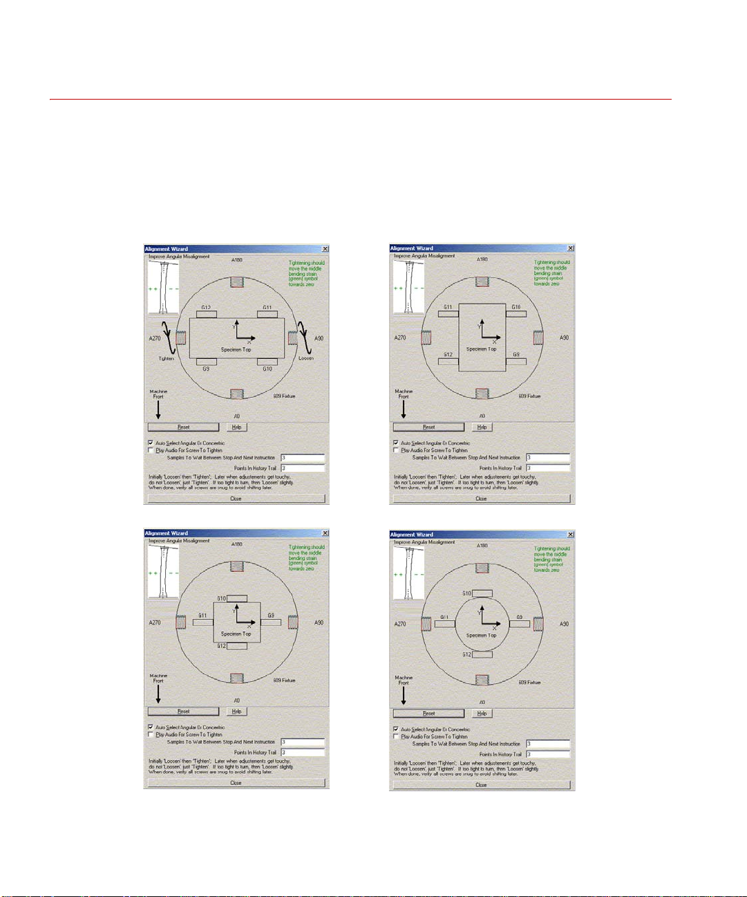
Align 93
Alignment Wizard 97
Angular Adjustments 100
If the X coordinate is positive 101
If the X coordinate is negative 102
If the Y coordinate is positive 103
If the Y coordinate is negative 104
Concentric Adjustments 105
Crosshead Mounted 609 Alignment Fixture 106
If the upper gauge X coordinate is positive 106
If the upper gauge X coordinate is negative 107
If the upper gauge Y coordinate is positive 108
If the upper gauge Y coordinate is negative 109
Base Mounted 609 Alignment Fixture 110
If the upper gauge X coordinate is negative 110
If the upper gauge X coordinate is positive 111
If the upper gauge Y coordinate is negative 112
If the upper gauge Y coordinate is positive 113
Validate 115
Legend 117
Data Acquisition 119
Start/Resume/Stop/Clear 119
Data acquisition with static load 120
Data acquisition with dynamic load 121
Pass/Fail indicators 122
4
Contents
709 Alignment System
Page 5

File Output 123
Fill 127
Report 128
Report Generator and Templates 129
Run Report Generator 130
MTS Provided Templates 132
Creating Custom Templates 133
Appendix 145
Resetting the FP-20xx 146
Resetting the FieldPoint Configuration 147
Possible Local Area Connection Problems 148
Possible Problem with Large Fonts 149
Changing the FieldPoint IP Address Sub-Net 150
FLEXlm Licensing Error 151
Firewall Licensing Error 153
Using the 793 Station Manager Function Generator 154
709 Alignment System Contents
5
Page 6

6
Contents
709 Alignment System
Page 7

Preface
Safety first! Before you attempt to use your MTS system, read and understand all safety
Contents About This Manual 8
information. Safety information can be found in a separate Safety manual or in a
section titled “Safety Practices” in one of the manuals in your documentation set.
Improper installation, operation, or maintenance of your system can result in
hazardous conditions that can cause personal injury or death, and damage to your
equipment and specimen. It is very important that you remain aware of hazards
that apply to your system.
What You Are Expected to Know 9
Conventions 10
Technical Support 11
709 Alignment System Preface
7
Page 8

About This Manual
About This Manual
This manual includes information on installing and operating the MTS
Alignment software. The 709 Alignment software works in conjunction with
the MTS Model 609 Alignment Fixture and strain-gaged specimens. There are
options in the 709 Alignment software that allows specimens with fewer
channels to be used for alignment.
Preface
8
709 Alignment System
Page 9

What You Are Expected to Know
What You Are Expected to Know
Microsoft Windows
knowledge
You should have a working knowledge of the Microsoft Windows operating
system before you use your system. For example, you should be able to:
• Use the mouse.
• Maneuver around the desktop.
• Locate, open, close, copy, and save documents.
If you are not sure how to do these things, take some time to learn them before
you continue.
Testing knowledge A premise of this manual is that you have had some experience or exposure to
servohydraulic testing, or access to someone who has.
709 Alignment System Preface
9
Page 10

Conventions
Conventions
Notes Notes provide additional information about operating your system or highlight
Control names References to items shown in windows, including window names, window
Illustrations Illustrations appear in this manual to clarify text. It is important for you to
The following paragraphs describe some of the conventions that are used in your
MTS manuals.
easily overlooked items. For example:
Note Using multiple instances of the scope (on multiple stations) can slow
system response time.
controls, menu names, and menu commands are shown in bold font style.
References to controls on equipment, including keyboards, control panels, and
consoles are also shown in bold font style.
remember that these illustrations are examples only and do not necessarily
represent your actual system configuration or application.
10
Preface
709 Alignment System
Page 11

Technical Support
Technical Support
Start with your
manuals
Technical support
numbers
MTS web site
www.mts.com
E-mail: info@mts.com
Telephone HELPLine 800-328-2255
The manuals supplied by MTS provide most of the information you will need to
use and maintain your equipment. If your equipment includes MTS software, you
should look for README files for additional product information.
If you cannot find answers to your technical questions from these sources, you
can use the internet, telephone, or fax to contact MTS for assistance. You can also
fill out the Problem Submittal Form that is available on the MTS web site and in
the back of many MTS manuals that are distributed in paper form.
MTS provides a full range of support services after your system is installed. If
you have any questions about a system or product, contact MTS in one of the
following ways.
The MTS web site gives you access to our technical support staff by means of a
Problem Submittal Form and a Technical Support link.
• Problem Submittal Form:
www.mts.com > Contact MTS > Problem Submittal Form
• Technical Support:
www.mts.com > Contact MTS > Technical Support
Weekdays 7:00 A.M. to 6:00 P.M.,
Central Time
Fax 952-937-4515
Please include an MTS contact name if possible.
709 Alignment System Preface
11
Page 12

Technical Support
Before you
contact MTS
Know your site number
and system number
Know information from
prior technical
assistance
MTS can help you more efficiently if you have the following information
available when you contact us for support.
The site number contains your company number and identifies your equipmen t
type (material testing, simulation, and so forth). The number is usually written on
a label on your MTS equipment before the system leaves MTS. If you do not
have or do not know your MTS site number, contact your MTS sales engineer.
Example site number: 571167
When you have more than one MTS system, the system number identifies which
system you are calling about. Y ou can find your job number in the papers sent to
you when you ordered your system.
Example system number: US1.42460
If you have contacted MTS about this problem before, we can recall your file.
You will need to tell us the:
• MTS notification number
• Name of the person who helped you
Identify the problem Describe the problem you are experiencing and know the answers to the
following questions.
• How long has the problem been occurring?
• Can you reproduce the problem?
• Were any hardware or software changes made to the system before the
problem started?
• What are the model and serial numbers of the suspect equipment?
Know relevant computer
information
Preface
12
If you are experiencing a computer problem, have the following information
available.
• Manufacturer’s name and model number
• Operating software type and service patch information. Examples:
– Windows Vista
– Windows XP Service Pack 1 (SP2)
• Amount of system memory. Example: 640 MB of RAM.
• Amount of free space on the hard drive in which the application resides.
Example: 11.2 GB free space, or 72% free space.
• Current status of hard-drive fragmentation. Example: 3% total
fragmentation.
709 Alignment System
Page 13

Technical Support
Know relevant software
information
If you contact MTS
by phone
For MTS software application problems, have the following information
available.
• The software application’s name, version number, build number, and if
available, software patch number. This information is displayed briefly
when you launch the application, and can typically be found in the “About”
selection in the “Help” menu.
Example: Station Manager, Version 3.3A, Build 1190, Patch 4
• The same information for other MTS software included with your system
• Names of other non-MTS applications that are running on your computer,
such as screen savers, keyboard enhancers, print spoolers, and so forth
Your call will be registered by a HELPLine agent if you are calling within the
United States or Canada. Before connecting you with a technical support
specialist, your agent will ask you for your site number, name, company,
company address, and the phone number where you can normally be reached.
Identify system type To assist your HELPLine agent with connecting you to the most qualified
technical support specialist available, identify your system as one of the
following types:
• Electromechanical materials test system
• Hydromechanical materials test system
• Vehicles test system
• Vehicles component test system
• Aero test system
Be prepared to
Prepare yourself for troubleshooting while on the phone.
troubleshoot
• Call from a telephone close to the system so that you can try implementing
suggestions made over the phone.
• Have the original operating and application software media available.
• If you are not familiar with all aspects of the equipment operation, have an
experienced user nearby to assist you.
709 Alignment System Preface
13
Page 14

Technical Support
Write down relevant
information
After you call MTS logs and tracks all calls to ensure that you receive assistance and that action
Problem Submittal
Form in MTS manuals
Prepare yourself in case we need to call you back.
• Remember to ask for the notification number.
• Record the name of the person who helped you.
• Write down any specific instructions to be followed, such as data recording
or performance monitoring.
is taken regarding your problem or request. If you have questions about the status
of your problem or have additional information to report, please contact MTS
again.
In addition to the Problem Submittal Form on the MTS web site, there is also a
paper version of this form (postage paid) in the back of many MTS manuals. Use
this form to forward problems you are experiencing with your MTS equipment,
whether it be software, hardware, manuals, or service. This form includes check
boxes that allow you to select when you expect us to respond to your input. We
guarantee a timely response—your feedback is important to us.
14
Preface
709 Alignment System
Page 15

Introduction
This manual includes information on installing and operating the MTS 709
Alignment software. The 709 Alignment software works in conjunction with
the MTS Model 609 Alignment Fixture and strain-gaged specimens. There are
options in the 709 Alignment software that allows specimens with fewer
channels to be used for alignment.
What you need to
know
Contents 709 Alignment Software 16
MTS Systems Corporation assumes that you know how to use your controller.
See the appropriate manual for information about performing any controllerrelated step in this manual’s procedures. You are expected to know how to
perform the following procedures:
• Turn hydraulic pressure on and off (servo hydraulics only)
• Select a control mode
• Position the load train components
• Zero a sensor signal
• Zero a sensor output
• Use your grips and fixtures
• Define a simple test
• Run a test
609 Alignment Fixture 17
Additional Information 18
709 Alignment System Introduction
15
Page 16
709 Alignment Software
709 Alignment Software
MTS 709 Alignment system includes the hardware and software to acquire,
analyze, and display bending strains for alignment and bending strain verification
purposes. Its graphical interface allows you to quickly align your system or
verify how much bending strain is being applied to the specimen. One of the key
attributes of this software is that it can separate the bending strain of the
specimen from that of the tensile strain.
The best method of determining bending strain is to use a strain-gaged specimen.
The software interfaces directly with a strain-gaged specimen and displays
bending strain graphically on the monitor of your PC. Continual scanning of
bending strains allows you to align your system or verify the bending strain at
various levels that will occur during the test. For reports, a text data file can be
written to disk and opened in Microsoft Excel for further analysis and customer
report generation.
709 Alignment software requires an alignment specimen with a 37-pin
D-connector. The software also requires Windows 2000 or later and a dedicated
RJ45 ethernet connector. Calibrated load can be displayed with an analog I/O
channel.This is required for some certifications such as ASTM E1012. Thin and
thick flat specimens, as well as round specimens are supported.
16
Introduction
The 709 Alignment System includes data acquisition with conditioning,
software, a manual, and connections for ethernet, analog I/O, and an alignment
specimen. See “Hardware Installation” on page 27 for addition information.
709 Alignment System
Page 17

609 Alignment Fixture
The MTS Model 609 Alignment Fixture for material testing systems that saves
time compared to manual alignment methods. A product information manual is
provided describing the alignment process and the use of strain-gaged specimens.
The main feature of the 609 is its capability to perform alignment adjustments
while the load train is fully loaded. This eliminates any inaccuracies involved in
trying to account for the small changes in alignment that frequently occur during
the preloading process. In addition, because the fixture remains preloaded at all
times, previous alignment adjustments are not lost when small changes in
alignment are required.
These alignment fixtures are readily adaptable to other load units as well. Refer
to the Model 609 Alignment Fixture Product Information manual (MTS part
number 015-031-901) for any special adapter kit that might be required in
addition to the alignment fixture.
609 Alignment Fixture
709 Alignment System Introduction
17
Page 18

Additional Information
Additional Information
The following documents provide additional and background information as it
pertains to the importance of proper specimen and machine alignment in
materials testing.
• S-400-E: Certified Materials Test Laboratories (CMTL): Metallic Materials
• SAE AS7101 Revision B - NADCAP Alignment Requirements
• ASTM E 1012 - 99: Standard Practice for Verification of Specimen
Alignment Under Tensile Load
• Versailles Project on Advanced Materials and Standards (VAMAS)
Technical Working Area 13, Low Cycle Fatigue
Recent Intercomparisons on Low Cycle Fatigue and Alignment
Measurements
Report No. 41
ISSN 1016-2186
February 2003
18
Introduction
• Versailles Project on Advanced Materials and Standards (VAMAS)
Technical Working Area 13, Low Cycle Fatigue
A Procedure for the Measurement of Machine Alignment in Axial Testing
Report No. 42
ISSN 1016-2186
February 2003
709 Alignment System
Page 19

CE Hardware Specifications
PARAMETER SPECIFICATION
Additional Information
Environmental
Ambient Temperature
Relative Humidity
Altitude
Power Input
Input Voltage
Input Frequency
AC Power
Insulation Over
Voltage
Pollution Degree
AC Power Disconnect Remove the AC power cord from the power supply.
For Indoor Use Only
5°C (41°F) 40°C (104°F)
10% to 85%, non-condensing
For use at altitudes up to 2000m (6500 ft.)
Power Factor Corrected Universal Input
100 to 240 VAC
47 to 63 Hz
< 100 Watts
Category II
2
This will remove AC power from the 709 Alignment
System.
Be sure to locate the power supply so you have
adequate access to disconnect the power cord from
the power supply.
709 Alignment System Introduction
19
Page 20

Additional Information
20
Introduction
709 Alignment System
Page 21

Alignment Procedure Overview
Following is an overview of a typical alignment procedure. It is intended as a
guide and will apply to most system configurations.
1. Check the controller setup and tuning before inserting the alignment
specimen instrumented with strain gauges: With no specimen clamped in the
grips, verify the stroke control tracks without drift. With an expendable
specimen clamped in the grips, verify the load control smoothly tracks a
slow (less than 1 Hz) function generator ramp.
2. Insure that the specimen is properly connected to the 709 electronics. Wait
20 to 30 minutes to insure there are no temperature gradients.
3. Confirm the specimen geometry and end levels in the specimen tab. The end
levels are typically set to the Load @ 2000 µe shown in the second column.
4. In the align tab, check the specimen offsets. Do this by toggling between
None, Current Tare, and Specime n Gauge. Current Tare and Specimen
Gauge (stored and averaged offsets) should be very close (within 5%). If
they are not, the Specimen Gauge offsets should be cleared and reestablished.
5. With the system in displacement control install the specimen in the lower
grip (or upper grip if desired). Clamp that end of the specimen in the grip.
6. Zero the load cell.
7. Move the actuator until the other end of the specimen is in the proper
location of the other grip is in position to clamp.
8. Now check to see if the Bent Offset is properly established. Do this by
toggling between Current Tare and Bent Offset. Normally , you should see
very little change between Current Tare and Bent Offset. Note that Bent
Offset is not really needed unless the specimen is not straight (i.e. has
manufacturing eccentricities or has been deformed).
709 Alignment System Alignment Procedure Overview
21
Page 22

9. Once the offsets are established, the actual alignment can take place. Make
sure the specimen is in the front orientation.
10. Clamp the other grip.
11. Switch the controller to load control.
12. Zero the load command.
13. Start the Alignment Wizard.
14. Follow the adjustment recommendations.
15. Gather data as described in the validation section of the manual.
16. To improve the alignment validation, you might wish to re-measure the bent
offset (possibly less prone to 180 degree rotation error when the machine is
better aligned) and adjust the alignment a little more.
Alignment Procedure Overview
22
709 Alignment System
Page 23

Installation
Contents Obtain the License File and NIC Installation 25
Installation of the 709 Alignment system consists of both hardware and software
installations.
The hardware installation consists of cabling the 709 Alignment System
hardware to the network and system controller, connecting the specimen strain
gauge connector, and connecting the power cord.
The software installation consists of installing the National Instruments Feild
Point software, the .Net Framework, and the 709 Alignment software application.
Hardware Installation 27
709 Alignment System Installation 27
Specimen Installation 30
Software Installation 32
.Net Framework Installation 33
709 Alignment Software Installation 35
National Instruments (NI) FieldPoint Installation 39
Upgrading The Firmware Located On The FieldPoint FP-2000
Hardware 45
TCPIP Configuration 47
FieldPoint Configuration 52
MTS Licensing Software Installation (New License) 58
Updating MTS Licenses (Replacement License) 64
709 Alignment System Installation
23
Page 24
Typical installation environments
For peer to peer connections, a crossover ethernet cable is required.
For networked connections, a standard ethernet cable is required.
24
Installation
709 Alignment System
Page 25

Obtain the License File and NIC Installation
Obtain the License File and NIC Installation
Before you install the licensing software later in this section, you will need to
obtain a license file.
One license file is supplied for each 709 alignment system.
In a networked connection environment, the license file is created for the PC with
the NIC, which will be the “server” and any other PC on the network will be a
“client”. The client will use the same license file as used for the server in order to
install the MTS licensing software. The server PC will need to be running for the
client PC to run the Alignment software.
In most cases, the 709 Alignment system will be configured at MTS and the
licence file will be created and shipped with the system. However, in some cases,
the 709 Alignment system will be configured on site and you will need to obtain
a license file from the factory. If you already have a license, you only need to
install the network interface card (NIC) and skip the rest of this procedure.
T o obtain the license file, you need to get the Physical Address of the NIC and
send that physical address number to MTS. MTS will then send you the license
file required for the MTS licensing software installation.
1. The 709 Alignment software comes with two batch files that will retrieve
the information MTS needs to provide you with the license file. To start
with, insert the 709 Alignment software CD in the computer’s Compact
Disk drive. Copy the two batch files (IPConfigAfter.bat and
IPConfigBefore.bat) to your C:\ drive.
2. The first batch file should be run before you install the NIC; this will
retrieve physical addresses of any network card(s) that might already be
installed and generate a text file that contains that information. Locate the
file IPConfigBefore.bat that you just copied to your C:\ drive and dou ble
click to run it.When IPConfigBefore.bat is done running, a text file
(IPConfigBefore.txt) is generated and placed on your C:\ drive.
709 Alignment System Installation
25
Page 26

Obtain the License File and NIC Installation
3. Install the network interface card. Instructions for installing the NIC into the
computer and loading the appropriate drivers are supplied with the card.
4. The second batch file should be run after you install the NIC; this will
retrieve the physical addresses of all network cards including the one just
installed for the 709 Alignment system. Running this batch file also
generates a text file with the physical address information. Locate the file
IPConfigAfter.bat that you just copied to your C:\ drive and double click to
run it. When IPConfigAfter.bat is done running, a text file
(IPConfigAfter.txt) is generated and placed on your C:\ drive.
5. Open the two text files (IPConfigBefore.txt and IPConfigAfter.txt).
Compare the two files to find the Physical Address of the Ethernet adapter
you just added (which is not in IPConfigBefore.txt). Email the Host Name
(which is listed in both files) and the Physical Address to
709license@mts.com.
6. Yo u will be sent the license file on a floppy disk or as an attachment to a
reply email. You will need this in Step 6 of the MTS Licensing Software
Installation (New License) section.
26
Installation
709 Alignment System
Page 27

Hardware Installation
709 Alignment System Installation
Connect the 709 Alignment System as follows:
1. If Load From Analog Input Signal will be used (see “Load Analog Input
Signal” on page 66), connect the analog I/O cable from the system
controller. (Cabling for this connection must be supplied by the customer.)
For most MTS testing systems, this will be from the TestStar Controller
Analog 1 output configured for the load/force signal.
2. Connect the network cable.
The network connection can be to either a site network or directly to the
computer.
If the 709 Alignment System will be connected to a site network, ensure that
it is on the same subnet as the computer that will be used for the alignment
procedure.
Hardware Installation
3. Connect the alignment specimen cable.
Specimens purchased from MTS have the strain gages wired into a
37-pin D connector. If you are supplying your own specimen, refer to the
specimen wiring diagram for connector pin assignments.
4. Plug in the power cord to apply power to the 709 Alignment System.
There is no on/off switch on the 709 Alignments System.
Verify all modules in the 709 Alignment System box are seated properly
(both down on the base and sideways against the adjacent modules) and
have green lights for Power and Ready. If necessary, push on the end to
slide the modules towards the power supply.
709 Alignment System Installation
27
Page 28
Hardware Installation
Specimen
connection
Network
connection
Analog I/O connection
(Load cell signal from
Test Con tro ller)
Power
connection
Standard Configuration
709 Alignment System
cable connections
Installation
28
709 Alignment System
Page 29
Specimen
connection
Network
connection
Analog I/O connection
(Load cell signal from
Test Controller)
Power
connection
CE Configuration
Dip switch
settings
Protective earth ground. Connect the
ground terminal to the system safety
ground using 14 AWG (1.6mm) wire.
Hardware Installation
709 Alignment System Installation
29
Page 30
Hardware Installation
Thin
Thick Round
Thin - rotate 90 degrees
Specimen Installation
When installing the specimen in the grips, ensure the orientation of strain
gauge 12 (G12) with respect to the 609 Alignment Fixture matches the
following illustrations. G12 must be positioned as shown with respect to the
609 adjustments (A0, A90, A180, A270, C0, C90, C180, C270), for the
alignment wizard and 609 Alignment Fixture adjustments to function
properly.
30
Installation
709 Alignment System
Page 31

Hardware Installation
RED
WHT
BLK
RED
WHT
BLK
RED
WHT
BLK
RED
WHT
BLK
RED
WHT
BLK
RED
WHT
BLK
RED
WHT
BLK
RED
WHT
BLK
RED
WHT
BLK
RED
WHT
BLK
RED
WHT
BLK
RED
WHT
BLK
EXC
VIN +
COM
CH 0
EXC
VIN +
COM
CH 1
EXC
VIN +
COM
CH 2
EXC
VIN +
COM
CH 3
EXC
VIN +
COM
CH 4
EXC
VIN +
COM
CH 5
EXC
VIN +
COM
CH 6
EXC
VIN +
COM
CH 7
EXC
VIN +
COM
CH 8
EXC
VIN +
COM
CH 9
EXC
VIN +
COM
CH 10
EXC
VIN +
COM
CH 11
20
1
2
21
3
22
23
4
5
24
6
25
26
7
8
27
9
28
29
10
11
30
12
31
32
13
14
33
15
34
35
16
17
36
18
37
12
11
10
9
8
7
6
5
4
3
2
1
12
11
10
9
8
7
6
5
4
3
2
1
D-37P
Specimen wiring
diagram
709 Alignment System Installation
31
Page 32

Software Installation
Software Installation
Software installation consists of installing several pieces of software:
• .Net Framework Installation
• 709 Alignment Software Installation
• National Instruments (NI) FieldPoint Installation
• Upgrading The Firmware Located On The FieldPoint FP-2000 Hardware
• TCPIP Configuration
• FieldPoint Configuration
• MTS Licensing Software Installation (New License)
• Updating MTS Licenses (Replacement License)
The software is supplied on two CDs: one containing the 709, .Net, and CVI
runtime software, and one containing the FieldPoint software.
Demo mode The 709 Alignment software can also run in a demonstration mode. If you will
only be running the software in the demo mode, only the procedures for the
“.Net Framework Installation” on page 33 and the “709 Alignment Software
Installation” on page 35 need to be performed. The remaining installation
procedures are not required.
Remove previous installations
Important When upgrading from previous versions to version 3.3.1 of the 709
1. Select Add/Remove Programs in the Control Panel:
Start > Settings > Control Panel > Add/Remove Programs
2. Select MTS 709 Alignment. Click Remove.
3. A dialog window appears asking you to confirm the removal; click Yes.
4. When removal is complete, click Finish.
5. Repeat steps 1 through 4 for the Microsoft .Net Framework and the NI
FieldPoint applications.
Installation
32
Alignment software, all previous versions of 709 Alignment
software, .Net Framework, and FieldPoint must be removed.
709 Alignment System
Page 33

.Net Framework Installation
The MTS 709 Alignment software runs within the 2.0 .Net framework. Use the
following procedure to install the 2.0 .Net framework. If your system already has
the 2.0 .Net framework installed, you can skip this procedure.
1. Insert the 709 Alignment software CD in the computer’s Compact Disk
drive.
2. Start the .Net Framework installation.
A. Log in to your computer as an administrator.
B. Make sure no other programs are running.
C. Double click My Computer.
D. Double click the Compact Disk drive icon in which the 709 Alignment
software CD is installed.
E. Double click the DotNetSetup folder.
F. Double click the dotnetfx.exe icon. The initial installation dialog
appears. Click Yes.
Software Installation
3. As the .Net Framework setup is being installed, the progress is displayed.
709 Alignment System Installation
33
Page 34

Software Installation
4. After setup is installed, the licence agreement is displayed. Click I agree
then click Install to begin installation. The progress is displayed as the
installation progresses.
34
Installation
5. When installation is complete. the following information dialog is
displayed. Click OK to finish the installation.
709 Alignment System
Page 35

709 Alignment Software Installation
To install the 709 Alignment software, proceed as follows:
1. Start the software installation program.
The software installation program is run from an executable called
setup.exe. Perform the following steps:
A. Log in to your computer as an administrator.
B. Make sure no other programs are running.
C. Insert the MTS 709 Alignment software CD.
D. Double-click the My Computer icon.
E. Double-click the MTS 709 Alignment Software CD icon.
F. Double-click the 709AlignSetup folder con.
G. Double-click on the setup.exe file to start the application installation.
H. The MTS 709 Alignment main window is displayed.
Software Installation
2. Read the welcome message and click Next.
709 Alignment System Installation
35
Page 36

Software Installation
3. Select the installation folder and click Next. It is recommended that you
accept the default installation location. In most cases you would change the
veryone/Just me selection to Everyone.
E
36
Installation
709 Alignment System
Page 37

Software Installation
4. At this point you are given a chance to go back and make any changes in the
previous windows. If your selections have been satisfactory, click Next. If
you need to make changes, click Back to revert to previous installation
windows.
5. Read the licence agreement, Click I Agree to accept the licence agreement,
and click Next to begin installation.
709 Alignment System Installation
37
Page 38

Software Installation
6. As the 709 Alignment software is being installed, the progress is displayed.
7. When installation is complete, click Close. Although not required, it is
recommended you restart your system.
38
Installation
709 Alignment System
Page 39

National Instruments (NI) FieldPoint Installation
The NI FieldPoint installation consists of installing the FieldPoint software and
configuring the 709 Alignment System with an TCP/IP Address.
Note Always use the FieldPoint setup supplied on the FieldPoint software CD.
Other versions of FieldPoint might not be compatible and can cause a
FieldPoint error when running the 709 Alignment software.
1. Insert the FieldPoint software CD in the computer’s Compact Disk drive.
2. Start the FieldPoint installation.
A. Log in to your computer as an administrator.
B. Make sure no other programs are running.
C. Double click My Computer.
D. Double click the Compact Disk drive icon in which the FieldPoint
software CD is installed.
E. Double click the FieldPointSetup folder.
Software Installation
F. Double click the autorun.exe icon.
The FieldPoint menu window appears. Click the Install FieldPoint option.
709 Alignment System Installation
39
Page 40

Software Installation
3. The initial welcome window appears. Read the information shown. When
the installer has finished initializing, click Next.
40
Installation
709 Alignment System
Page 41

Software Installation
4. Read the licence agreement, click the I accept the licence agreement
choice and click Next.
709 Alignment System Installation
41
Page 42

Software Installation
5. Change the features to install. Selections should match the illustration
below.
42
Installation
709 Alignment System
Page 43

Software Installation
6. At this point, installation is ready to proceed. If you want to make any
changes to previous selections, use the Back button to return to previous
windows where you can change your selections. If you are satisfied with the
selection’s you have made, click Next to begin the installation.
7. Once installation starts, a progress window is displayed.
709 Alignment System Installation
43
Page 44

Software Installation
8. When installation is complete, click Finish to exit the installation program.
44
Installation
709 Alignment System
Page 45

Software Installation
Upgrading The Firmware Located On The FieldPoint FP-2000 Hardware
General Information The current version of the 709Align application is compatible with FieldPoint
6.0.3 software and firmware.
If the 709Align application is being installed on an existing system as an upgrade
to an older version of 709Align, the firmware residing on the FieldPoint FP-2000
hardware may need to be upgraded. The following information details the steps
in performing the firmware upgrade.
Upgrading FieldPoint
Firmware
1. From the Windows Task Bar:
Click on Start > Programs > National Instruments > Measurement and
Automation. This launches the Measurement and Automation application.
2. In the left window pane, click on Software. This displays the dialog in the
right window pane shown above.
709 Alignment System Installation
45
Page 46

Software Installation
3. On the top of the right window pane, click on “Add/Remove Software”.
This displays the following dialog.
4. Select the “FieldPoint 6.0.3” item as shown below.
46
Installation
5. Click the “Next” button.
6. Follow the remaining steps to download the new firmware to the FieldPoint
hardware.
709 Alignment System
Page 47

TCPIP Configuration
Two procedures for the TCPIP configuration are provided:
• TCPIP Configuration for Systems Running Windows XP
• TCPIP Configuration for Systems Running Windows 2000
Before configuring the TCPIP address, it is recommended to unplug all network
cables except for the connection to the FieldPoint. This will ensure that the
TCPIP address is being configured for the proper device.
Note for Windows Vista Systems
Systems running Windows Vista should use the TCPIP Configuration for
Systems Running Windows XP procedure as a reference. When setting the IP
address and Subnet Mask in step 5, the Default gateway might need to be set to
the same value as the IP address.
TCPIP Configuration for Systems Running Windows XP
1. Click on Start menu bar. Click on Control Panel menu item
Software Installation
2. Double click on “Network Connections” icon
709 Alignment System Installation
47
Page 48

Software Installation
Enabled
Disabled
Note The Local Area Connection in the next step must be the one
associated with the added network interface card; typically Local Area
Connection #2. This connection must be enabled. If th e connection is
disabled (red X next to the icon), see “Possible Local Area Connection
Problems” on page 148 in the Appendix section for additional
information.
3. Right click on Local Ar ea Connection icon. Click on Properties menu
item.
4. Check Internet Protocol (TCP/IP) box. Click Properties button.
48
Installation
709 Alignment System
Page 49

Software Installation
5. Check Use the following IP address circle. Enter
10.0.0.1 for the IP
address; the last number can be any number other than 101. Enter
255.255.255.0 for the Subnet mask. Click OK.
709 Alignment System Installation
49
Page 50

Software Installation
Enabled
Disabled
TCPIP Configuration for Systems Running Windows 2000
1. Right click the My Network Places icon and select Properties.
Note The Local Area Connection in the next step must be the one
associated with the added network interface card; typically Local Area
Connection #2. This connection must be enabled. If th e connection is
disabled (red X next to the icon), see “Possible Local Area Connection
Problems” on page 148 in the Appendix section for additional information
2. Right click the Local Area Connection icon and select Properties.
50
Installation
709 Alignment System
Page 51

Software Installation
3. Highlight Internet Protocol (TCP/IP) and click Properties.
4. Select Use the following IP address. Enter the address assigned by your
network administrator. If you have not been assigned an address, the address
as shown in the following figure should work for most situations.
709 Alignment System Installation
51
Page 52

Software Installation
FieldPoint Configuration
Once the NI FieldPoint is installed, you need to configure the Measurement and
Automation Explorer software and configure the TCP/IP Address.
1. Open the Measurement & Automation Explorer from the Start menu:
Start > National Instruments > Measurement & Automation
An initial splash screen appears momentarily and the Measurement &
Automation Explorer window appears.
52
Installation
709 Alignment System
Page 53

Software Installation
Enabled
Disabled
B
A
C
D
Note If the FieldPoint has already been configured, you can skip to step 4.
2. Set up the IP address.
A. Expand the Remote System selection (double click or click the +).
Note If there is a warning icon ( ) next to the FieldPoint device, it indicates a
communication problem. If the Local Area Connection (on page 40)
status shows enabled (i.e. no red X) then see “Resetting the FP-20xx” on
page 146 in the Appendix section for additional information
B. Expand 0.0.0.0.
C. Ensure the Network Setti ngs tab is selected.
D. Enter IP address 10.0.0.101.
709 Alignment System Installation
53
Page 54

Software Installation
B
A
C
3. Apply the IP Address.
A. Click Apply.
B. A dialog window opens explaining the changes will not take effect
until the system is rebooted; the system in this case is the FieldPoint
system, not the computer.
C. After the FieldPoint system reboots, the IP address is displayed.
54
Installation
709 Alignment System
Page 55

Software Installation
4. From the Tools menu, select FieldPoint > Open.
5. Locate the Config10.0.0.101.iak file. This file is install e d during the 709
Alignment software installation and typically located in the 709Align folder
on the C: drive; see “709 Alignment System Installation” on page 27. Click
Config10.0.0.101.iak to select it and click Open.
709 Alignment System Installation
55
Page 56

Software Installation
B
A
C
D
E
Note If the FieldPoint has already been configured, you can skip the next step.
6. If this is a new installation and the FieldPoint has not been configured
before, you will get a warning message saying values do not match current
file settings for each unconfigured module.
A. Click OK
B. Ensure FP-SG-140@1 is selected.
C. In the File/Device Conflict Resolution, select File and click Use
These Settings.
D. In the Channel Attributes, ensure the Excitation Voltage is 5
Volts.
E. Repeat for FP-SG-140@2 and FP-AI-110@3.
56
Installation
709 Alignment System
Page 57

Software Installation
A
B
C
D
E
F
7. Verify that the FieldPoint has been configured properly and data acquisition
is functioning.
A. Expand Data Neighborhood down to FP Res.
B. Click (select) FP-SG-140@1.
C. Click Start.
D. Verify that Range and Timestamp values are being recorded. If all
strain gages are being used, all Status checks should be successful. If
some of the strain gages are not being used, the status might be out of
range.
E. Click Stop.
F. Repeat steps C through E for FP-SG-140@2 and FP-AI-110@3.
709 Alignment System Installation
57
Page 58

Software Installation
MTS Licensing Software Installation (New License)
Before installing the MTS Licensing software, make sure you have the license
file available. See “Obtain the License File and NIC Installation” on page 25 for
additional information.
There is a separate setup on the 709 Alignment software CD for installing the
MTS licensing software.
Note Before you install the MTS Licensing sof tware, make sure the system
clock and date are set correctly. If the date is incorrect, the software can
lock up and you will not be able to be run the alignment software.
1. Insert the 709 Alignment software CD in the computer’s Compact Disk
drive.
2. Start the MTS License installation.
A. Log in to your computer as an administrator.
B. Make sure no other programs are running.
C. Double click My Computer.
58
Installation
D. Double click the Compact Disk drive icon in which the 709 Alignment
software CD is installed.
E. Double click the MTSLicenseSetup folder.
F. Double-click on the Setup.exe file to start the MTS License
installation.
709 Alignment System
Page 59

3. Read the welcome message and click Next.
4. Read the licence agreement and click Yes.
Software Installation
709 Alignment System Installation
59
Page 60

Software Installation
5. Select the installation type based on your network environment and click
Next.
• For Peer-to-Peer Connection select Server.
• For Networked Connection:
–Click on Server if this PC has the NIC (Ethernet) card (whose
network address is specified in the 709 Alignment license file).
Server must be selected if there is only one PC. See “Obtain the
License File and NIC Installation” on page 25.
–Click on Client if this PC does NOT have the Ethernet card (whose
network address is specified in the 709 Alignment license file).
The licensing software must first be installed on the server PC,
before installing on a client PC (both must be connected to the
same network).
60
Installation
709 Alignment System
Page 61

Software Installation
6. If you received a license floppy, insert it at this time. Verify the server name
in the mts_license.dat file.
A. Insert the 709 Alignment software CD in the computer’s Compact
Disk drive. Copy the batch file IPConfigAfter.bat to your C:\ drive.
B. Locate the file IPConfigAfter.bat that you just copied to your C:\
drive and double click to run it.When IPConfigAfter.bat is done
running, a text file (IPConfigAfter.txt) is generated and placed on
your C:\ drive.
C. Open the IPConfigAfter.txt and note the host name.
D. Open the mts_license.dat with a text editor . Compare the host name in
the IPConfigAfter.txt file with the server name in the mts_license.dat
file. If necessary, change the mts_license.dat file to match the
IPConfigAfter.txt file.
709 Alignment System Installation
61
Page 62

Software Installation
7. If this is a client installation and a license server contains a license file for
your PC, browse to the location of the license file on network drive when
prompted by the installation for the license file.
62
Installation
709 Alignment System
Page 63

Software Installation
8. At this point you are given a chance to go back and make any changes in the
previous windows. If your selections have been satisfactory, click Next, and
the MTS software license will be installed. If you need to make changes,
click Back to revert to previous installation windows.
9. During installation, several screens will flash indicating installation
progress. When installation is successful, an information dialog is
displayed; click OK.
709 Alignment System Installation
63
Page 64

Software Installation
Updating MTS Licenses (Replacement License)
Use the following procedure to install a new license that replaces a license that
has expired or when a replacement ethernet card is installed.
1. Do not uninstall or reinstall the MTS License Manager.
2. Verify the new license file (e.g. A:\mts_license.dat) has the correct server
name as the current license file (e.g. C:\MTS\License\mts_license.dat).
Refer to Step 6 in the previous procedure, MTS Licensing Software
Installation (New License).
3. Copy the new license file and replace the old license file.
Reboot the PC or restart the service if the 709 Alignment software gets an license
error.
64
Installation
709 Alignment System
Page 65

Options
Contents FieldPoint Data Acquisition 66
The Options tab provides information about the FieldPoint data acquisition
settings, global settings that apply to everyone in the lab, and user preferences for
customizing the display for individual users.
Global Settings 66
User Preferences 69
709 Alignment System Options
65
Page 66

FieldPoint Data Acquisition
Validate tab x-axis selections
Options tab
Analog input selections
Strain Gauge selections
The fields in this section of the tab show the read only parameters relating to the
FieldPoint hardware.
Global Settings
Load Analog Input
Signal
The entries in this area define the parameters relating to the load signals used by
the 709 alignment software.
Add - Click this button to add a load input signal. This could be a load signal
from a second load cell for a given load unit, a load signal from a different
calibrated load range, or a load signal from another load frame station.
Remove - Deletes the load signal shown in the pulldown menu field.
Gain - This field defines the scaling used by the 709 Alignment software when
displaying or graphing the load analog input signal.
check box - The Enable in Align and Validate tabs check box, when checked,
enables the load analog input signal to be displayed in the indicated tabs; AI in
the Align tab Load bar graph, Load (AI) in the Validate tab.
Validate Chart X-Axis These radio buttons determine whether the analog input (AI) or the strain gauges
(SG) will be used for the validate chart. The choice here also determines the
starting selection for the x-axis on the validate chart.
Options
66
709 Alignment System
Page 67

Thin Rectangular
Options tab
Align tab
Specimen Orientation
Typically, for systems using the thin rectangular specimen, the mounting
orientation of the specimen will be such that the back of the specimen (G12) will
face the back of the test machine (load unit). However, because of mounting
requirements for some systems (for example, side loading grips inside an
environmental chamber), the specimen might be mounted such that the front of
the specimen faces to one side on the test machine.
When the Turn 90 Degrees Sideways In Grips is checked, the software adjusts
the readouts and displays on the Align tab.
709 Alignment System Options
67
Page 68

609 Alignment Fixture
Mounting Location
In most cases the 609 Alignment Fixture is mounted to the crosshead. However,
some situations require mounting the 609 Alignment Fixture to the base.
Mounting the 609 fixture to the base requires the concentric adjustment
instructions in the alignment wizard be reversed. This option lets you select
where the 609 fixture is mounted and changes the concentric alignment
instructions in the alignment wizard accordingly.
68
Options
709 Alignment System
Page 69

User Preferences
Significant Digits To
Display
The entry in this field defines the number of significant digits displayed for the
values on the Specimen, Align, and Validate tabs.
Validate Target Limit Selecting Strain Trough here will cause the target on the validate screen to be
displayed in strain.
Selecting Percent Level here will cause the target on the validate screen to be
displayed in percent.
709 Alignment System Options
69
Page 70

Bending Percent The 709 Alignment software offers two choices for calculation bending percent.
e12100=
e22000=
e31900=
a
e
1e2e3
++
3
---------------------------=
a 2000=
b1e1a–=
b1100=
b2e2a–=
b20=
b3e3a–=
b
3
100–=
B
b
1
2
3
------ -
b
2
b
1
---- -
1
2
-- -+
⎝⎠
⎛⎞
•atancos
----------------------------------------------------------------=
B 115=
Bmaxb1 b2 b
3
()()=
B 100=
e12100=
e22100=
e31900=
e41900=
a
e
1e2e3e4
+++
4
-------------------------------------- -=
a 2000=
b1e1a–=
b1100=
b2e2a–=
b2100=
b3e3a–=
b
3
100–=
b4e4a–=
b
4
100–=
B
1
2
-- -
b1b3–()2b2b4–()
2
+=
B 141=
Bmaxb1 b2 b3 b
4
()()=
B 100=
One complies with MTS’s interpretation of ASTM 1012 and the other to MTS’s
interpretation of GEAE S-400. In general, you would select the method that
satisfies your particular auditing requirements. Following are the calculations for
each method.
Cylindrical specimens,
three strain sensors
ASTM E 1012 True Max
GEAE S-400 Simple Max
Cylindrical specimens,
four strain sensors
ASTM E 1012 True Max
GEAE S-400 Simple Max
Options
70
709 Alignment System
Page 71

Display Units This selection determines whether the values are displayed in English or metric
Options tab
Align tab
units on the Specimen, Align, and Validate tabs.
Days Reminder for
License Renewal
This can be used as a reminder that the licence needs to be renewed. Once this
number of days has been reached, a reminder message will appear when the 709
Alignment software is started.
Align Load Chart This selection determines what signals are displayed in the load chart on the
Align tab. As indicated, the load analog input signal (AI) is only displayed if the
signal is enabled in the Global Settings.
709 Alignment System Options
71
Page 72

Align Bending Chart The selections in this area define how the upper (red), middle (green), and lower
(blue) indicators in the bending strain alignment graph are displayed. The
following illustration shows some examples.
The Use Solid Symbols is only applicable when there isn't a history trail
(because there is only one symbol you can choose outline or solid).When there is
a history trail, the current symbol is always solid and the history is always
outline. The history trail is composed of the specified number of previous points
which decrease in size.
Validate Text Box The selections in this group define how the test displays in the text box of the
Validate tab.
• Word Wrap (when text box fills the window)
72
Options
When this box is checked, the information displayed in the text box will wrap
onto the next line if it does not fit. Word wrap is useful when reading the
comments of the specimen, which might be longer than can fit in the width of the
window. Word wrap might not be desired when viewing the data because the
rows of values will wrap onto the next line making it hard to distinguish which
row is part of which line. This text box is normally on the right of the Validate
tab, in which case it does not word wrap because the text box is so narrow. This
word wrap option is only in effect when the text box has been enlarged to fill the
window (by clicking the 'Fill' button).
709 Alignment System
Page 73

Note Move the mouse cursor outside of the text box (e.g., to the top of the
Fill button
Move cursor outside
text box to restore
original view.
window - that is the area containing the window title) to restore the
original view.
• Replace with u
For some applications, when opening the text data file, there can be
problems displaying the Greek symbol . Under normal conditions, strain is
represented by the greek symbol . If your system cannot display the Greek
symbol, check this box to replace the symbol with the letter u in the
709 Alignment System Options
Validate text bo x and the text file written to disk.
73
Page 74

Use Black Instead of
Color Lines On
Validate Screen
If this box is checked, the lines connecting the data point markers in the graphical
display area of the Validate tab will be black instead of matching the color of the
data point marker. This can improve printing in black and white.
Do Not Save User
Preferences When
Options
74
Exiting
If this box is checked, user preferences defined on the Options tab will not be
saved when the program is closed; that is, changes will be ignored. This can be
useful when changing the appearance of the software for the current instance
only, and reverting back to the original conditions next time. This also applies to
the check box options on the Alignment Wizard.
709 Alignment System
Page 75

Specimen
Open/Save As/Save The Open button allows you to open an existing specimen file. Save As allows
you to save the information shown on the Specimen tab to a file with a different
file name. Save allows you to save the information shown on the Specimen tab
into the current file.
Note The software automati cally attempts to open the last specimen when it
launches.
709 Alignment System Specimen
75
Page 76

Channel Calculation This selection determines which set of gages are used to calculate the applied
load and the axial strain. The Middle Gauges are typically used for 12-channel
specimens. The other settings can be used when fewer channels are available, all
12 channels are not functioning properly, or for diagnostic purposes. For
example, if an 8-channel specimen is used (a specimen with only the upper and
lower gauges attached), typically the Ave Upper + Lower selection would be
chosen. Another example, Middle Only can be selected when the specimen does
not have upper nor lower gauges. Not having upper and lower gauges prevents
the calculation of concentric misalignment. The specimen can be used to validate
angular misalignment (as in MTS’s interpretation of Mil Std 1312 B appendix
C0).
Cross Section Type This selection determines the type of specimen being used for specimen
alignment. The thick specimen has gauges on all four sides similar to the round
°specimen. The thin specimen has gauges on the front and back surfaces.
4x90
The round 3x120
°specimen has gauges equally spaced about the circumference.
Parameter Units This selection defines the units type used on the Specimen tab.
76
Specimen
709 Alignment System
Page 77

Target Class This selection defines the target class for the alignment resolution.
400
300
200
100
0
0
Class 20
-3000 -2000 -1000 1000 2000 3000
Class 10
Class 5
Class 2
Compression
Axial Strain, a (micro-strain)
Tension
Maximum bending strain, b
max.mc
(micro-strain)
The level of the machine alignment can be described according to the criteria
specified in the following table and shown graphically in the following figure
where:
a is the axial strain
b
β
CLASS ABS (A) < 1000 MICRO-STRAIN ABS (A) ≥ 1000 MICRO-STRAIN
is the maximum bending strain
max.mc
is the percent bending
mc
2
5
10
20
709 Alignment System Specimen
b
max.mc
b
max.mc
b
max.mc
b
max.mc
≤ 20 micro-strain
≤ 50 micro-strain
≤ 100 micro-strain
≤ 200 micro-strain
β
mc
β
mc
β
mc
β
mc
≤ 2%
≤ 5%
≤ 10%
≤ 20%
77
Page 78

Target Strain This field shows the value of the target strain defined by the Target Class
selection. This is also the value of the target area on the graph displayed on the
Align tab.
Specimen Parameters The values in these fields are entered by the user and define the alignment
specimen. The specimen dimensions available (Specimen Diameter, Rectangular
Width, Distance to Edge) are determined by the cross section type of the
specimen. The Axial Boundary is explained in a following paragraph; see “Axial
Boundary” on page 79.
78
Specimen
The other specimen parameters in the grayed fields and calculated values based
on the user entered values for the specimen above.
709 Alignment System
Page 79

Axial Boundary This feature avoids the situation where the bending percent become infinite as the
axial strain gets very small (i.e. when zero load is applied). The default value is
200 µe.
When the axial strain is within this range, the bending percent will not be
calculated or displayed on the graph, so the text box and data file will show NaN
(Not a Number) for the bending percent. The Validation Status will show if the
data passes or fails the bending percent criteria only for the values that are
calculated. The Reports and the Validation Status will still agree because the NaN
will be shown where the bending percent is not calculated.
The bending percent is not plotted when the axial strain is within the boundary,
which will create a gap in the bending percent line. If the axial strain crosses over
the boundary to the other side, then the bending percent line will cross over the
boundary. The strain will still be plotted even if the axial strain is within the
boundary. When plotting strain and percent, the strain data point in the boundary
will not have a corresponding percent data point.
709 Alignment System Specimen
79
Page 80

If the user starts sampling data when at no load, the graph will not change,
although the progress bar and text box will. If the user is accustomed to watching
the data as it is plotted, it may appear that the software is not sampling because
the graph is not changing.
A gap is displayed in the bending percent target level to represent the axial strain
boundary.
80
Specimen
709 Alignment System
Page 81

Offsets The offsets section of the Specimen tab shows the offset values determined by
performing the specimen offsets procedure.See “Specimen Offsets” on page 83
for additional information.
709 Alignment System Specimen
81
Page 82

82
Specimen
709 Alignment System
Page 83

Specimen Offsets
Strain Offset Relationship
The bent front and bent back measurements are taken before the gauge offset is
removed, therefore both the bent front and bent back offset values include the
gauge offset. Because the bent mean offset is the average of the bent front and
bent back values, it also includes the gauge offset, and is always in the middle of
the bent front and bent back when graphed. The following figure (Strain Offset
Relationship) shows this relationship for the middle gauges.
It is noteworthy to determine the amount of bending that is due to the
straightening of the specimen, and the amount of bending that is due to the
misalignment of the load unit. The bending due to the straightening of the
specimen is interesting because it indicates how straight the specimen was
manufactured and can potentially indicate if the specimen has deformed over
time due to use, handling, etc. The bending due to the misalignment of the load
unit is interesting because it indicates how well the load unit was aligned when
the bent mean was calculated. A large load unit misalignment can conceivably
cause more error in the bent front and bent back measurements, and thus lead to
more error in the calculated bent mean value.
709 Alignment System Specimen Offsets
83
Page 84

Conceptually, the graphed bent measurements can be reached by adding vectors.
Bending Strain Depiction
First there is the bending due to the gauge offsets, then add the bending if the
specimen were bent straight, and then add the load unit imposed bending (bent
front or bent back). The following figure (Bending Strain Depiction) shows this
depiction for the middle gauges.
Specimen Offsets
84
709 Alignment System
Page 85

T o see the bending due to the straightening of the specimen, the gauge offset can
Bending Components
be subtracted from the bent mean offset (bent mean relative to the gauge offset).
T o see the bending due to the misalignment of the load unit, the bent mean offset
can be subtracted from the bent front offset (bent front relative to the bent mean).
The bending has X and Y components for each:
Xs – specimen bending strain in the x-axis
Ys – specimen bending strain in the y-axis
Xm – load unit bending strain in the x-axis
Ym – load unit bending strain in the y-axis
The following figure (Bending Components) shows the specimen bending and
load unit bending components for the midd le gauges.
709 Alignment System Specimen Offsets
85
Page 86

Printable Symbols
Printable Symbols
The Use Printable Symbols option on the Specimen Offsets window allows
you to select either unique printable shapes for each symbol or change the solid
symbol to correspond to the selected tab.
Specimen Offsets
86
709 Alignment System
Page 87

Get Specimen Offset Values
A
B
Note It is recommended that the lo ad unit be aligned prior to setting the
specimen offset values. In order to get an accurate specimen offset
reference, the load unit should first be aligned.
A typical sequence to get the specimen offset values would be:
1. Start the 709 Alignment program.
A. Select the Align tab.
B. Click Specimen Offsets.
Get Specimen Offset Values
709 Alignment System Specimen Offsets
87
Page 88

Get Specimen Offset Values
2. Establish the gauge offset reading.
Because specimens cannot be perfectly machined and placement of the
strain gauges on the specimen cannot be perfectly aligned, some initial
offsets are inherent.
A. Select the Gauge tab.
B. Click the Read button to take a reading.
C. Click the Add button to save the values.
D. Wait for approximately 15 seconds.
E. Repeat steps B, C, and D until you have saved three sets of gauge
values.
Specimen Offsets
88
These values will be used when the Specimen Gauge selection is active in
the Use Offsets section of the Align tab.
709 Alignment System
Page 89

Get Specimen Offset Values
3. Establish the bent front offset reading.
Because load train components cannot be perfectly machined, some initial
offsets are inherent. Establishing bent front values allows the 709 Alignment
System to take this into account during the alignment adjustments.
A. Select the Bent Front tab.
B. Install and clamp the specimen in the standard orientation; that is
install the specimen such that gauges G4, G8, and G12 are facing
toward the front on the load unit with G4 being the top gauge.
C. Click the Read button to take a reading.
D. Click the Add button to save the values.
E. Unclamp and clamp the lower grip.
F. Repeat steps C, D, and E until you have saved three sets of bent front
values.
G. Unclamp and clamp the upper grip.
H. Click the Read button to take a reading.
I. Click the Add button to save the values.
J. Repeat steps G, H, and I until you have saved three sets of bent front
values.
709 Alignment System Specimen Offsets
89
Page 90

Get Specimen Offset Values
4. Establish the bent back offset reading.
Because load train components cannot be perfectly machined, some initial
offsets are inherent. Establishing bent back values allows the 709 Alignment
System to take this into account during the alignment adjustments.
A. Select the Bent Back tab.
B. Install and clamp the specimen in the standard orientation; that is
install the specimen such that gauges G4, G8, and G12 are facing
toward the back on the load unit with G4 being the top gauge.
C. Click the Read button to take a reading.
D. Click the Add button to save the values.
E. Unclamp and clamp the lower grip.
F. Repeat steps C, D, and E until you have saved three sets of bent front
values.
G. Unclamp and clamp the upper grip.
H. Click the Read button to take a reading.
I. Click the Add button to save the values.
J. Repeat steps G, H, and I until you have saved three sets of bent back
values.
Specimen Offsets
90
709 Alignment System
Page 91

Get Specimen Offset Values
5. Check the bent mean offset values.
The bent mean values are the average of both the bent front and bent
back values taken in steps 3 and 4. These values will be used when the
Specimen Bent selection is active in the Use Offset section of the
Align tab.
Also included are the X and Y bending components due to the specimen
and the load unit:
• bending strain due to straightening the specimen (bent mean offset
relative to the gauge offset)
Xs - bending strain in the x-axis
Ys - bending strain in the y-axis
• bending strain due to load unit misalignment (bent front offset relative
to the bent mean offset)
Xm - bending strain in the x-axis
Ym - bending strain in the y-axis
709 Alignment System Specimen Offsets
91
Page 92

Get Specimen Offset Values
Specimen Offsets
92
709 Alignment System
Page 93

Align
The Align tab provides a variety of displays to indicate the alignment process.
On the left side, numerical values are displayed for the gages and bending offsets.
In the center, a bar graph shows the load values. Depending on the check box
selections in the Options tab, one or two bars wil l be displaye d. The Strain bar is
the load calculated from stain based on the setting on the Specimen tab. The
Signal bar is the scaled Load Analog Input Signal based on the gain on the
Options tab.
On the right, points representing the bending strain are plotted on a x-y graphical
coordinate system. The color coding of these points on the graph on the right
directly relates to the color coding of the specimen gauge values on the left.
709 Alignment System Align
93
Page 94

Note There could be a display problem if large fonts are selected in the display
properties. See “Possible Problem with Large Fonts” on page 149 in the
Appendix section for additional information.
Note Although the shade d area of the graph will always be rectangular, the
actual target area is within the oval (or circle) outline for round
specimens (as shown below) or within the diamond outline for
rectangular specimens.
Chart Interaction You can use the chart interaction options to view specific areas of the graph.
• Translation: Shift + Drag with left mouse button.
• Scaling: Control + Drag with left mouse button.
• Zooming: Alt + Drag with left mouse button.
T o undo the interaction, use the options to revert back to the original display, use
the Plot Bending Set and Reset buttons, or restart the application.
94
Align
709 Alignment System
Page 95

Plot Bending In this section you can select the plot to be in Strain values or Percent. The Auto
Scale feature, when checked, will automatically scale the graph on the right of
this tab as the points representing the load values of the three gauges approach
the target microstrain.
If Auto Scale is not checked you can set the full scale range on the graph using
the Set button. or set the graph to optimum scale using the Reset button.
Specimen Offsets Clicking this button will bring up the specimen offsets window. See “Specimen
Offsets” on page 83 for additional information.
Use Offset In this section you select the offset for compensating the displayed values. None
for no offset, just the raw reading. Specimen Gauge or Specimen Bent offset
from the specimen offset procedure. Or Current Tare, which uses the current
reading to zero out the values.
Alignment Wizard Pressing this button brings up the alignment wizard to aid in alignment
adjustments. See “Alignment Wizard” on page 97 for additional information.
709 Alignment System Align
95
Page 96

96
Align
709 Alignment System
Page 97

Alignment Wizard
Once the system is functional with the alignment specimen installed, actual
alignment of the test frame and force train components involves loosening and
tightening various set screw adjustments on the 609 Alignment Fixture. The
following sections give you some guidelines as to which adjustments to either
tighten or loosen depending on the actual state of the system.
Contents Angular Adjustments 100
If the X coordinate is negative 102
If the X coordinate is positive 101
If the Y coordinate is negative 104
If the Y coordinate is positive 103
Concentric Adjustments 105
Crosshead Mounted 609 Alignment Fixture 106
If the upper gauge X coordinate is positive 106
If the upper gauge X coordinate is negative 107
If the upper gauge Y coordinate is positive 108
If the upper gauge Y coordinate is negative 109
Base Mounted 609 Alignment Fixture 110
If the upper gauge X coordinate is negative 110
If the upper gauge X coordinate is positive 111
If the upper gauge Y coordinate is negative 112
If the upper gauge Y coordinate is positive 113
709 Alignment System Alignment Wizard
97
Page 98

If the alignment wizard and 609 Alignment Fixture adjustments are not
functioning properly, ensure the specimen is installed properly in the grips, such
that the orientation of strain gauge 12 (G12) with respect to the 609 Alignment
Fixture matches the graphics in that alignment wizard. G12 must be positioned as
shown with respect to the 609 adjustments (A0, A90, A180, A270, C0, C90,
C180, C270). See “Specimen Installation” on page 30 for additional information.
Note Before preforming the alignment adjustments, the system should be
warmed up to a stable operating temperature. That is, system high
hydraulic pressure should be applied and the alignment specimen
installed in the grips and clamped for at least 30 minutes before
performing the alignment adjustme n ts.
Generally you make the angular adjustments first, then the concentric
adjustments. Also be aware that all adjustments are somewhat interactive; that is,
one adjustment will have some affect on the others. The purpose of the
information in this section is to provide you with guidelines in performing a
system alignment. In practice, system alignment using the 709 Alignment System
is empirical. Once you get a feel of what happens when the various angular and
concentric adjustment screws and loosened/tightened, the adjustment process
will be intuitive.
Note If the Alignment fixture screws cannot be adjusted, or the feedback is not
responding as indicated, reduce the alignment fixture preload by 50%.
Refer to the Installation section of the Model 609 Alignment Fixture
Product Information manual (MTS part number 015-031-901) for
information on preloading the alignment fixture.
Alignment Wizard
98
Note Another possible cause of adjustment problems could be a bent
specimen. In this case, redoing the specimen offsets could fix the
problem. See “Specimen Offsets” on page 83 for additional information.
709 Alignment System
Page 99

The alignment wizard is a graphical tool that shows you in real time what
If Auto Select Angular Or Concentric is checked,
the wizard will automatically switch to show which
adjustment is most out of alignment. If this is not
checked, you can switch back and forth using the Go
T o Concentric and Go to Angular buttons. In either
case, the Tighten and Loosen arrows will always
show which adjustment is most out of alignment.
If Play Audio For Screw To Tighten is checked, a
synthesized voice will tell you which screw should be
tightened.
The entry in the Samples To Wait Between Stop
And Next Instruction field specifies the number of
samples the software will wait once the symbol has crossed (green crosses zero or red crosses blue)
before determining the next adjustment instruction to tighten/loosen the appropriate setscrew. This is
useful because the bending strain often springs back once the wrench is removed, so the wait allows
the bending strain to settle such that the worst misalignment component can be properly determined.
The entry in the Points in History Trail field is the same as the similar entry on the Options tab; see
“Align Bending Chart” on page 72. The number of history trailing points can be edited either here or
on the Options tab.
Clicking the Close button will close the Alignment Wizard.
adjustments need to be made. You bring up the alignment wizard by clicking the
Alignment Wizard button on the Align tab. It shows which particular
adjustments need to be made based on which ones are most out of adjustment.
709 Alignment System Alignment Wizard
99
Page 100

Angular Adjustments
Angular Adjustments
Angular adjustments are done using the middle gauge (green) as a guide. The
following paragraphs describe which adjustment screws to loosen/tighten
depending on the value of the middle (green) gauge reading. The goal of the
angular adjustments on the 609 Alignment Fixture (A0, A90, A180, and A270) is
to adjust these screws to get the middle gauge reading as close to 0,0 as practical.
Following is an example of the alignment wizard showing angular adjustments.
Alignment Wizard
100
709 Alignment System
 Loading...