

Page 1

Model 685.53 Grip Control Module
Product Information
l
015-029-701 C
Page 2

Copyright information © 1992 - 2004 MTS Systems Corporation. All rights reserved.
Trademark information MTS is a registered trademark of MTS Systems Corporation.
Contact information MTS Systems Corporation
14000 Technology Drive
Eden Prairie, Minnesota 55344-2290 USA
Toll Free Phone: 800-328-2255 (within the U.S. or Canada)
Phone: 952-937-4000 (outside the U.S. or Canada)
Fax: 952-937-4515
E-mail: info@mts.com
http://www.mts.com
Publication information
Manual Part Number Publication Date
150297-01A November 1992
150297-01B January 1999
015-029-701 C August 2000
015-029-701 C
* Style changes only. No revision letter change required.
July 2004
*
Page 3

Contents
Introduction 5
Functional Description 6
Specifications 7
Installation 9
Crush Point Hazards 10
Installation Procedure 11
Operation 15
Controls 16
Determining the Grip Operating Pressure 18
Adjusting the Output Pressure 19
Adjusting the Rate Control 20
Gripping Specimens 21
Removing Specimens from the Grips 23
Model 685.53 Grip Control Module Contents
3
Page 4

4
Contents
Model 685.53 Grip Control Module
Page 5
Introduction
Contents Functional Description 6
The Model 685.53 Hydraulic Grip Control Module provides an easy way to grip
specimens for testing. It mounts on the front of a load unit or grip supply to
provide control of the hydraulic grips. The Model 685.53 Hydraulic Grip Control
Module is a control only; it depends on an external source for hydraulic pressure.
Specifications 7
Hydraulic Grip Control
What you need to
know
Pressure
56
4
7
8
9
10
Rate
3
2
1
MTS Systems Corporation assumes that you know how to use your controller.
See the appropriate manual for information about performing any controllerrelated step in this manual’s procedures. You are expected to know how to
perform the following procedures.
• Turning hydraulic pressure on and off
• Selecting a control mode
• Manually adjusting the actuator position
• Installing a specimen
• Defining a simple test
• Running a test
Model 685.53 Grip Control Module Introduction
5
Page 6
Functional Description
Functional Description
The 685.53 Hydraulic Grip Control Module is designed to provide the hydraulic
grip control for specimen grips and includes the following features.
• Hydraulic flow control determines how fast the grips operate.
• The hydraulic pressure can be adjusted between 0.7 and 20.7 MPa (100 and
3000 psi).
• Provides independent grip/release control for each of two grips.
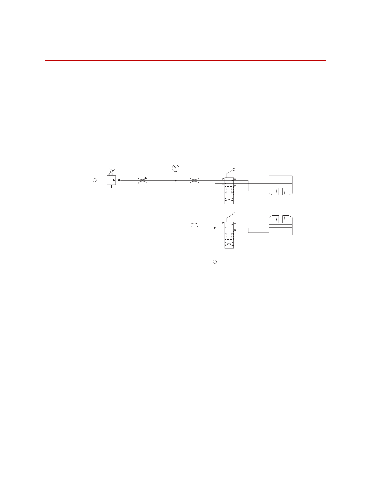
Hydraulic schematic The following figure shows the hydraulic schematic for the grip control.
Hydraulic
Output
Hydraulic
Source
-4P
Rate
Control
Pressure
030 DIA
Upper Grip
Grip
Pressure Reducing Valve
0.720.7 MPa
(1003000 psi)
adjustment range
Grip Control Manifold
030 DIA
-6R
Hydraulic
Return
Release
Release
Grip
Lower Grip
Model 685.53 Hydraulic Schematic
Hydraulic power unit The Model 685.53 Hydraulic Grip Control Module gets its hydraulic pressure
from the hydraulic power unit in the lab.
Control manifold The control manifold outputs the hydraulic control to the grips. The control
manifold includes all of the front panel controls.
Rate control The Rate control is a needle valve that restricts the hydraulic flow, and
determines how fast the grips clamp and unclamp.
Pressure control The Pressure control establishes the final output pressure to the grips. It works in
conjunction with another pressure reducing valve which is being used as a
pressure relief valve. These two valves work in the same fashion as the valves on
the supply manifold.
6
Grip control The grip controls port the final output pressure to the grips. Each grip has two
Introduction
ports, a grip port and a release port. The grip controls change the output pressure
from the grip port to the release port and vice versa. The controls also have a
midpoint where the hydraulic pressure is stopped at the grip control; this causes
the grip to stop its hydraulic movement.
Model 685.53 Grip Control Module
Page 7

Specifications
The following table lists the hydraulic specifications for the grip control.
Parameter Specification
Maximum Input Pressure 21 MPa (3000 psi)
Specifications
Pressure Control Range
Pressure Stability
(at all pressures)
Grip and Pressure Fittings male, JIC 37º flare -6
Drain Fitting male, JIC 37º flare -4
0.7–21 MPa (± 0.06 MPa) (100–3000 psi (± 10 psi))
± 0.03 MPa (± 5 psi)
Model 685.53 Grip Control Module Introduction
7
Page 8

Specifications
8
Introduction
Model 685.53 Grip Control Module
Page 9

Installation
Contents Crush Point Hazards 10
Hydraulic Grip Control
Installing a Model 685.53 Hydraulic Grip Control module consists of installing
the control panel and manifold in the load unit and making the hydraulic hose
connections to the upper and lower grips.
Installation Procedure 11
Pressure
56
4
Rate
3
2
1
7
8
9
10
685.53 Control Module (Front)
Upper
Grip
From “Pressure” on
Lift/Lock Manifold
685.53 Control Module (Rear)
Upper
Release
Grip
Release
Upper
Upper
From “Drain” on
Lift/Lock Manifold
Lower
Grip
Lower
Release
Grip
Lower
Release
Lower
Model 685.53 Grip Control Module Installation
9
Page 10

Crush Point Hazards
Crush Point Hazards
It is important to stay clear of any potential crush points during installation or when
the system is operating. Know where the crush points are in your system and protect
yourself and others from those crush points with appropriate safety devices. The
following paragraphs describe crush points and precautions to take while working
around crush points, and apply to most systems.
ydraulicWedgeGri
p
H
7
4
6
6
4
7
H
ydraulicWedgeGri
Crush
p
Point
Areas
Locations A crush point exists between the platen and crosshead on load units where the
actuator piston rod and specimen move (both areas are shown). Another potential
crush point exists where the lower end of the actuator piston rod extends below
the platen and the bottom of the load unit/load frame.
Precautions Keep clear of any mechanical linkage that moves within a closed area. If the
linkage should move (when the system starts or due to mechanical failure), very
high forces can be present that could pinch, cut, or crush anything in the path of
linkage movement.
10
Installation
Never allow any part of your body to enter the path of machine movement or to
touch moving machinery, linkages, hoses, cables, specimens, and so forth. These
present serious crush points or pinch points.
Model 685.53 Grip Control Module
Page 11

Installation Procedure
Installing a Model 685.53 Hydraulic Grip Control module consists of installing
the control panel and manifold in the load unit and making the hydraulic hose
connections to the upper and lower grips. The following procedure assumes that
the grips to be controlled by the hydraulic grip supply have been properly
installed on a load unit.
Installation Procedure
WARNING
Never leave a crosshead unlocked.
It can drift slowly down when hydraulic pressure is turned off and damage
any test fixtures, grips, and specimen in its path.
Unlock the crosshead only to reposition it. Always lock the crosshead after
you have repositioned it.
1. Lock the crosshead on the load unit.
If the load unit has manual locks, tighten the crosshead clamping bolts
according to the sequence and torque settings specified in the load unit
product information manual.
If the load unit has hydraulic locks, use the Crosshead Lift/Lock
Controls to clamp the crosshead to its current position.
Wait 30 seconds for the locks to fully clamp the columns.
2. Turn off the load unit hydraulic pressure.
If you have a separate hydraulic service manifold, turn its hydraulic pressure
off also.
3. Switch off electrical power at the test controller.
Wait two minutes for pressure to fall to zero before opening any fittings.
4. Access the control panel.
A. Lift the baseplate cover to access the four screws securing the control
panel to the base.
CAUTION
Model 685.53 Grip Control Module Installation
Do not remove the control panel screws without restraining the possible
movement of the control panel.
The control panel is hinged. Unless restrained, the control panel will drop
when the screws that secure the control panel to the base are removed. The
control panel is heavy; when the last screw is removed, the control panel
will drop. possibly causing equipment damage.
When removing the screws that secure the control panel to the base, restrain the
panel to keep it from falling in an uncontrolled manner. When all screws are
removed, you can grasp the control panel and let it swing down in a controlled
fashion.
11
Page 12

Installation Procedure
B. Restrain the control panel and remove the four screws securing the
panel to the base.
C. Grasp the control panel and slowly lower it to the mechanical stop of
the securing cables.
5. Install the grip control module in the control panel.
Refer to the drawings that accompany the module and the illustrations on
page 9.
WARNING
WARNING
Do not use hydraulic hoses rated for less than 21 MPa (3000 psi).
Under-rated hoses may rupture and can cause injury to personnel or
damage to equipment.
Use only hydraulic hoses that have a working pressure greater than 21 MPa
(3000 psi).
6. Connect the hydraulics.
A. Connect the pressure (“P”) and drain (“D”) ports on the grip manifold
to the corresponding pressure and drain ports on the hydraulic lift/lock
manifold.
B. Connect the grip and release ports on the grip manifold to the
corresponding grip and release ports on each of the upper and lower
grips.
7. Switch electrical power on at the test controller.
Do not turn hydraulic pressure on without verifying that the control channel
error is zero.
A nonzero error may result in unexpected actuator movement and can
cause injury to personnel or damage to equipment.
12
Installation
Verify that the control channel error is zero before applying hydraulic pressure.
8. Turn load unit hydraulic pressure to low.
Inspect for leaks at all connections. If there are leaks, turn off hydraulic
pressure and correct them.
9. Turn load unit hydraulic pressure to high.
Inspect for leaks at all connections. If there are leaks, turn off hydraulic
pressure and correct them.
Model 685.53 Grip Control Module
Page 13

Installation Procedure
CAUTION
Do not clamp the grips without a specimen installed.
Some grips may be damaged by closing the grip without a specimen
inserted or with a specimen only partially inserted.
See the appropriate grip product information manual for detailed specimen
mounting instructions.
10. Check the grip operation.
Change the grip controls between grip and release a few times and check for
leaks at all connections (correct as needed).
11. Secure the control panel.
Lift the control panel back up to the base and secure with the screws
removed in Step 4. Do not overtighten.
12. Replace the baseplate cover.
Model 685.53 Grip Control Module Installation
13
Page 14

Installation Procedure
14
Installation
Model 685.53 Grip Control Module
Page 15

Operation
Contents Controls 16
This section describes how to use the hydraulic grip supply. Some operating
details depend on the particular grips you have. You should have your grip
product information manual available for specimen installation and removal
procedures.
Determining the Grip Operating Pressure 18
Adjusting the Output Pressure 19
Gripping Specimens 21
Removing Specimens from the Grips 23
Model 685.53 Grip Control Module Operation
15
Page 16

Controls
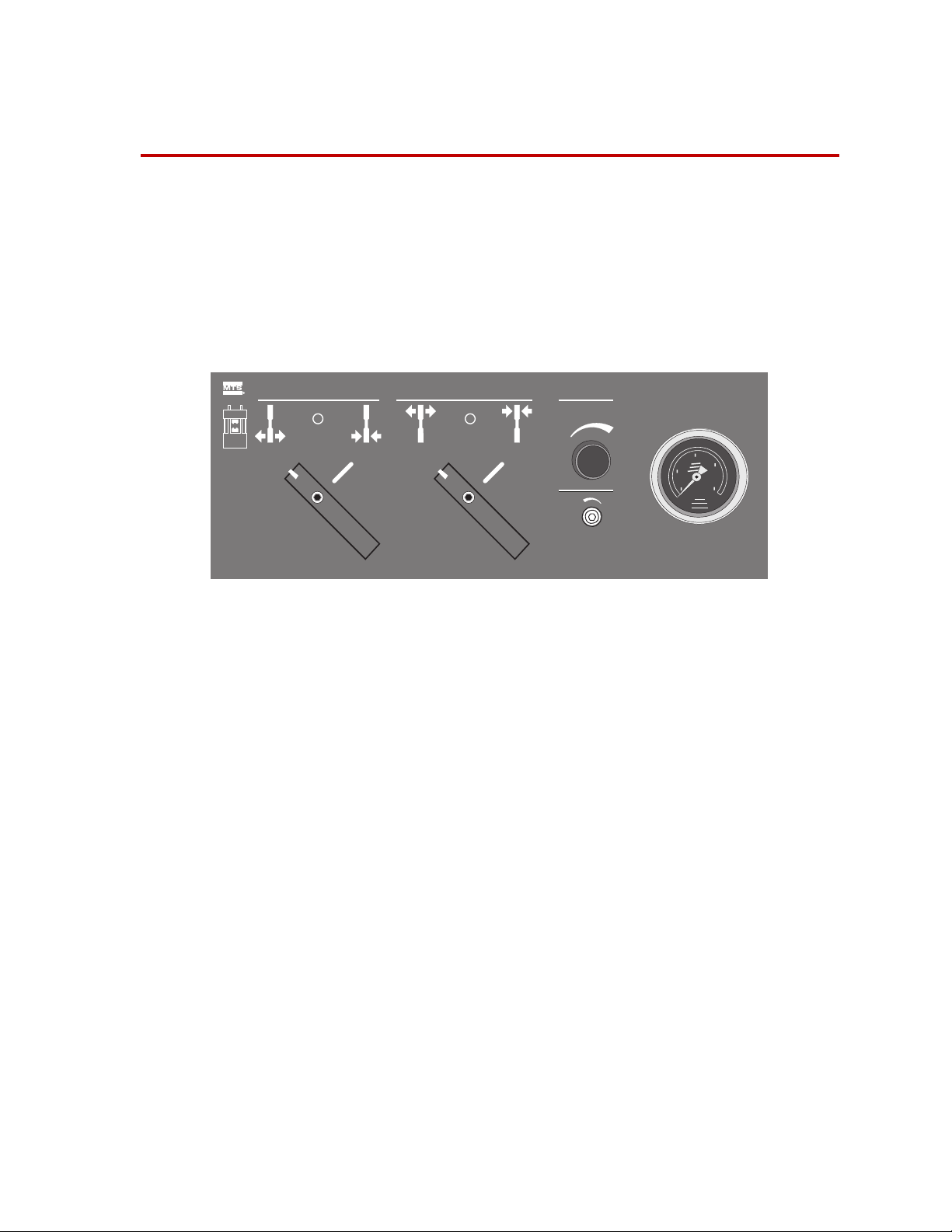
Controls
Hydraulic Grip Control
The controls and indicators are located on the control panel shown below.
Pressure
56
Rate
4
3
2
1
7
8
9
10
Control Description
Lower Grip Control
Upper Grip Control
Controls the lower grip for specimen installation and removal. The threeposition control can grip or release one end of a specimen.
This indicates the lower clamp is gripping the specimen. Turn the
control clockwise to clamp a specimen into the lower grip.
This indicates the lower clamp is open and not gripping a specimen.
Turn the control counterclockwise to release a specimen from the
lower grip.
The gripping action can be stopped midway between grip and ungrip by
putting the control midway between the two lower grip symbols.
Controls the upper grip for specimen installation and removal. The threeposition control can grip or release one end of a specimen.
This indicates the upper clamp is gripping the specimen. Turn the
control clockwise to clamp a specimen into the upper grip.
This indicates the upper clamp is open and not gripping a specimen.
Turn the control counterclockwise to release a specimen from the
upper grip.
The gripping action can be stopped midway between grip and ungrip by
putting the control midway between the two upper grip symbols.
16
Operation
Model 685.53 Grip Control Module
Page 17

Control Description
Controls
Pressure
Pressure
Rate
Rate
Pressure Gage
56
4
3
2
1
Adjusts the amount of hydraulic pressure applied to the grips for gripping the
specimen.
This is a multiturn knob. Pressure increases as the knob is turned clockwise
and decreases as the knob is turned counterclockwise.
To determine the correct operating pressure, see “Adjusting the Output
Pressure” on page 19.
Adjusts how fast the grips clamp and unclamp. This control requires the use of
a hex-key wrench for adjustment.
Adjust the Rate control clockwise to slow the clamping of the specimen.
Otherwise, adjust the Rate control counterclockwise to increase the clamping
speed.
To adjust the clamping rate, see “Adjusting the Rate Control” on page 20.
Shows the current hydraulic pressure setting for grip operation.
The gage includes scales for both MPa and psi units.
7
8
9
10
Use the gage while adjusting the Pressure control to achieve the desired
clamping pressure. See the grip product information manual for gripping
pressures.
Model 685.53 Grip Control Module Operation
17
Page 18

Determining the Grip Operating Pressure
Determining the Grip Operating Pressure
You must consider the following factors to determine the appropriate grip
operating pressure:
• The type of grips to be used
• The specimens to be tested
• The tests to be performed
• The model number of the grip supply
Grip product information manuals (from MTS) describe how to determine the
required operating pressure. They include formulas and/or graphs to determine
the grip pressure (also called minimum operating pressure). The minimum
pressure, as referred to in the grip manual, is the calculated least pressure that
will provide adequate gripping of the specimen while it is being tested at specific
maximum loads.
If practice indicates that the calculated pressure proves to be too low (because the
specimen slips under load due to hardness or other characteristics), then the
actual minimum pressure will have to be increased to provide adequate gripping.
Use the grip product information manual to determine the minimum grip
operating pressure that is best for the test situation at hand.
The grip control can be configured to produce different output pressures. Check
the model number specification. See “Adjusting the Output Pressure” on page 19
for the procedure.
18
Operation
Model 685.53 Grip Control Module
Page 19

Adjusting the Output Pressure
The output pressure of the hydraulic grip control determines the gripping force
applied to the specimen by the grips. The output pressure can be adjusted up to
the maximum output pressure of the system hydraulic power unit which is
usually 21 MPa (3000 psi).
1. Determine the required grip operating pressure.
See “Determining the Grip Operating Pressure” on page 18 and also see the
grip product information manual.
2. Put both grip controls in the release (open) position.
If it is necessary to adjust output pressure while there is a specimen in the
grips, install the specimen and turn the grip controls to the grip position
(clockwise).
3. Set the operating pressure.
Turn the Pressure control to obtain the desired operating pressure as shown
on the control panel pressure gage.
Adjusting the Output Pressure
Model 685.53 Grip Control Module Operation
19
Page 20

Adjusting the Rate Control
Adjusting the Rate Control
The Rate control may be adjusted at any time. If the grips act too fast to suit your
personal preference, turn the Rate control clockwise to slow the speed of grip
action. Turning the Rate control counterclockwise speeds up grip action.
Turning the Rate control fully clockwise stops the flow of fluid to the grips. If
the grips do not operate, check to be sure that the Rate control has not been
turned fully clockwise.
Adjustment of rate is a matter of personal preference. It should be based on the
desired speed of grip action during the gripping and ungripping processes. (The
speed of grip action is dependent both on the adjustment of the rate control and
the particular grips being used.)
When first operating the grips, use a slower speed (lower rate setting). Then
increase the operating speed to your satisfaction.
20
Operation
Model 685.53 Grip Control Module
Page 21

Gripping Specimens
Prerequisite This procedure assumes that the output pressure has been adjusted.
Have the appropriate grip product information manual handy for more specific
specimen mounting information.
Gripping Specimens
WARNING
Do not put anything in a crush zone when turning on hydraulic power.
Unexpected actuator movement can occur when hydraulic pressure is
turned on. This can cause personal injury or equipment damage.
Be sure you read and understand all safety information provided with your
system. Follow all applicable system operating procedures before turning on
hydraulic power.
Also, make sure that all systems or equipment that use the same hydraulic power
source are in appropriate condition for application of hydraulic power.
1. Select a force control mode to control the actuator.
Select force control at the system controller and use the most sensitive
(lowest load) range available.
If your controller has a channel-limited-channel control mode for specimen
installation, use one defined with displacement control and force limiting.
2. Release the grips.
Make sure that both grip controls are in the release position.
3. Apply full system hydraulic pressure.
Use applicable system procedures to turn on the system hydraulic pressure.
Model 685.53 Grip Control Module Operation
21
Page 22

Gripping Specimens
CAUTION
Do not clamp the grips without a specimen installed.
Some grips may be damaged by closing the grip without a specimen
inserted or with a specimen only partially inserted.
See the appropriate grip product information manual for detailed specimen
mounting instructions.
4. Grip the specimen as follows:
Because of the large variety of load frame, grip, and controller equipment in
use, it is impossible to give explicit instructions for this process.
Pliers or tong-like tools such as those used for installing or removing
cartridge-type electrical fuses are often used for holding small specimens in
proper position within the grips to lessen the possibility of having fingers
pinched or crushed during the gripping process.
Gripping a specimen typically involves manually holding the specimen in
place within the upper grip and then, with the specimen correctly in place,
applying hydraulic gripping pressure to the upper grip. And finally, it
involves moving the actuator as necessary to correctly position the lower
end of the specimen within the lower grip. Hydraulic gripping pressure is
then applied to the lower grip.
A. Perform any operations necessary to correctly position one end of the
specimen within the upper grip.
B. When the specimen is properly positioned within the upper grip, rotate
the upper grip control clockwise to the grip position.
C. Perform any operations necessary to correctly position one end of the
specimen within the lower grip.
D. When the specimen is properly positioned within the lower grip, rotate
the lower grip control clockwise to the grip position.
Note While applying test loads to specimens mounted in the grips, leave the
grip controls in the grip position.
22
Operation
Model 685.53 Grip Control Module
Page 23

Removing Specimens from the Grips
Removing Specimens from the Grips
Perform the following steps to remove a specimen from the grips.
WARNING
Do not put anything in a crush zone when turning on hydraulic power.
Heavy specimens or specimen fragments falling from the grips can injure
you or damage test equipment.
Take adequate precautions to support heavy specimens while releasing them
from the grips.
1. If needed, provide adequate support for the specimen, and turn the upper
grip control to the release position.
2. If the specimen is broken, remove the upper portion.
3. Determine whether it is necessary to reposition the crosshead or actuator to
provide adequate clearance for removal of the lower part of the specimen.
Reposition the crosshead or actuator, as needed.
4. If needed, provide adequate support for the specimen, and rotate the lower
grip control to the release position.
5. Remove the specimen.
Model 685.53 Grip Control Module Operation
23
Page 24

m
MTS Systems Corporation
14000 Technology Drive
Eden Prairie, Minnesota 55344-2290 USA
Toll Free Phone: 800-328-2255
(within the U.S. or Canada)
Phone: 952-937-4000
(outside the U.S. or Canada)
Fax: 952-937-4515
E-mail: info@mts.com
http://www.mts.com
ISO 9001:2000 Certified QMS
 Loading...