

Page 1

be certain.
m
Series 685 Hydraulic Grip Supply
Product Information
Model 685.10
Model 685.22
Model 685.60
100-241-254 A
Page 2

Copyright information © 2011 MTS Systems Corporation. All rights reserved.
Trademark information MTS is a registered trademark of MTS Systems Corporation within the United
States. This trademark may be protected in other countries.
Mobil 525 SHC is a registered trademark of Mobil Corporation.
Publication information
Manual Part Number Publication Date
100-241-254 A August 2011
2
Contents
Page 3

Contents
Technical Support 5
How to Get Technical Support 5
Before You Contact MTS 5
If You Contact MTS by Phone 6
Problem Submittal Form in MTS Manuals 7
Preface 9
Before You Begin 9
Conventions 10
Documentation Conventions 10
Introduction 13
Series 685 Grip Supply Component Identification 14
Series 685 Grip Supply Functional Description 15
Series 685 Grip Supply Hydraulic Schematics 16
Series 685 Grip Supply Specifications 18
Safety 19
General Safety Practices 19
Hazard Placard Placement 23
Power Loss Considerations 26
Installation 27
Lifting and Moving the Grip Supply 27
Series 685 Grip Supply Installation Procedure 29
Series 685 Grip Supply Product Information Contents
3
Page 4

Operation 33
Series 685 Grip Supply Controls and Indicators 33
Determining the Grip Operating Pressure 35
How to Adjusting the Output Pressure 35
About Rate Control 36
How to Grip a Specimen 37
How to Remove a Specimen from Grips 38
How to Recover from a Thermal Overload 39
Maintenance 41
Series 685 Grip Supply Maintenance Intervals 41
Hydraulic Fluid Maintenance 42
Remove the Series 685 Grip Supply Side Panels 43
Clean the Heat Exchanger 43
Replace the Hydraulic Fluid Filter Element 43
Grip Supply Transport or Storage Preparation 44
4
Contents
Series 685 Grip Supply Product Information
Page 5

Technical Support
How to Get Technical Support
How to Get Technical Support
Start with your
manuals
Technical support
methods
MTS web site
www.mts.com
E-mail tech.support@mts.com
Telephone MTS Call Center 800-328-2255
Fax 952-937-4515
The manuals supplied by MTS provide most of the information you need to use
and maintain your equipment. If your equipment includes MTS software, look
for online help and README files that contain additional product inform ation.
If you cannot find answers to your technical questions from these sources, you
can use the internet, e-mail, telephone, or fax to contact MTS for assistance.
MTS provides a full range of support services after your system is installed. If
you have any questions about a system or product, contact MTS in one of the
following ways.
The MTS web site gives you access to our technical support staff by means of a
Technical Support link:
www.mts.com > Contact Us > Service & Technical Support
Weekdays 7:00 A.M. to 5:00 P.M., Central Time
Please include “Technical Support” in the subject line.
Before You Contact MTS
MTS can help you more efficiently if you have the following information
available when you contact us for support.
Know your site
number and system
number
Series 685 Grip Supply Product Information Technical Support
The site number contains your company number and identifies your equipment
type (material testing, simulation, and so forth). The number is usually written on
a label on your MTS equipment before the system leaves MTS. If you do not
have or do not know your MTS site number, contact your MTS sales engineer.
Example site number: 571167
When you have more than one MTS system, the system job number identifies
which system you are calling about. You can find your job number in the papers
sent to you when you ordered your system.
Example system number: US1.42460
5
Page 6

If You Contact MTS by Phone
Know information from
prior technical
If you have contacted MTS about this problem before, we can recall your file.
You will need to tell us the:
assistance
• MTS notification number
• Name of the person who helped you
Identify the problem Describe the problem you are experiencing and know the answers to the
following questions:
• How long and how often has the problem been occurring?
• Can you reproduce the problem?
• Were any hardware or software changes made to the system before the
problem started?
• What are the model numbers of the suspect equipment?
• What model controller are you using (if applicable)?
• What test configuration are you using?
Know relevant
computer information
If you are experiencing a computer problem, have the following information
available:
• Manufacturer’s name and model number
• Operating software type and service patch information
• Amount of system memory
• Amount of free space on the hard drive in which the application resides
• Current status of hard-drive fragmentation
• Connection status to a corporate network
Know relevant
For software application problems, have the following information available:
software information
• The software application’s name, version number, build number, and if
available, software patch number. This information is displayed briefly
when you launch the application, and can typically be found in the “About”
selection in the “Help” menu.
• It is also helpful if the names of other non-MTS applications that are
running on your computer, such as anti-virus software, screen savers,
keyboard enhancers, print spoolers, and so forth are known and available.
If You Contact MTS by Phone
Your call will be registered by a Call Center agent if you are calling within the
United States or Canada. Before connecting you with a technical support
specialist, the agent will ask you for your site number, name, company , company
address, and the phone number where you can normally be reached.
Technical Support
6
Series 685 Grip Supply Product Information
Page 7

Problem Submittal Form in MTS Manuals
If you are calling about an issue that has already been assigned a notification
number, please provide that number. You will be assigned a unique notification
number about any new issue.
Identify system type To assist the Call Center agent with connecting you to the most qualified
technical support specialist available, identify your system as one of the
following types:
• Electromechanical materials test system
• Hydromechanical materials test system
• Vehicle test system
• Vehicle component test system
• Aero test system
Be prepared to
Prepare yourself for troubleshooting while on the phone:
troubleshoot
• Call from a telephone when you are close to the system so that you can try
implementing suggestions made over the phone.
• Have the original operating and application software media available.
• If you are not familiar with all aspects of the equipment operation, have an
experienced user nearby to assist you.
Write down relevant
Prepare yourself in case we need to call you back:
information
• Remember to ask for the notification number.
• Record the name of the person who helped you.
• Write down any specific instructions to be followed, such as data recording
or performance monitoring.
After you call MTS logs and tracks all calls to ensure that you receive assistance and that action
is taken regarding your problem or request. If you have questions about the status
of your problem or have additional information to report, please contact MTS
again and provide your original notification number.
Problem Submittal Form in MTS Manuals
Use the Problem Submittal Form to communicate problems you are experiencing
with your MTS software, hardware, manuals, or service which have not been
resolved to your satisfaction through the technical support process. This form
includes check boxes that allow you to indicate the urgency of your problem and
your expectation of an acceptable response time. We guarantee a timely
response—your feedback is important to us.
The Problem Submittal Form can be accessed:
• In the back of many MTS manuals (postage paid form to be mailed to MTS)
• www.mts.com > Contact Us > Problem Submittal Form (electronic form to
be e-mailed to MTS)
Series 685 Grip Supply Product Information Technical Support
7
Page 8

Problem Submittal Form in MTS Manuals
Technical Support
8
Series 685 Grip Supply Product Information
Page 9

Before You Begin
Preface
Before You Begin
Safety first! Before you attempt to use your MTS product or system, read and understand the
Safety manual and any other safety information provided with your system.
Improper installation, operation, or maintenance of MTS equipment in your test
facility can result in hazardous conditions that can cause severe personal injury or
death and damage to your equipment and specimen. Again, read and understand
the safety information provided with your system before you continue. It is very
important that you remain aware of hazards that apply to your system.
Other MTS manuals In addition to this manual, you may receive additional MTS manuals in paper or
electronic form.
If you have purchased a test system, it may include an MTS System
Documentation CD. This CD contains an electronic copy of the MTS manuals
that pertain to your test system, including hydraulic and mechanical component
manuals, assembly drawings and parts lists, and op eration and preventive
maintenance manuals. Controller and application software manuals are typically
included on the software CD distribution disc(s).
Series 685 Grip Supply Product Information Preface
9
Page 10

Conventions
DANGER
WARNING
CAUTION
Conventions
Documentation Conventions
The following paragraphs describe some of the conventions that are used in your
MTS manuals.
Hazard conventions As necessary, hazard notices may be embedded in this manual. These notices
contain safety information that is specific to the task to be performed. Hazard
notices immediately precede the step or procedure that may lead to an associated
hazard. Read all hazard notices carefully and follow the directions that are given.
Three different levels of hazard notices may appear in your manuals. Following
are examples of all three levels.
Note For general safety information, see the safety information provided with
your system.
Danger notices indicate the presence of a hazard with a high level of risk which,
if ignored, will result in death, severe personal injury, or substantial property
damage.
Warning notices indicate the presence of a hazard with a medium level of risk
which, if ignored, can result in death, severe personal injury, or substantial
property damage.
Caution notices indicate the presence of a hazard with a low level of risk which,
if ignored, could cause moderate or minor personal injury, equipment damage, or
endanger test integrity.
Notes Notes provide additional information about operating your system or highlight
easily overlooked items. For example:
Note Resources that are put back on the hardware lists show up at the end of
the list.
Special terms The first occurrence of special terms is shown in italics.
Illustrations Illustrations appear in this manual to clarify text. It is important for you to be
Electronic manual
conventions
Preface
10
aware that these illustrations are examples only and do not necessarily represent
your actual system configuration, test application, or software.
This manual is available as an electronic document in the Portable Document
File (PDF) format. It can be viewed on any computer that has Adobe Acrobat
Reader installed.
Series 685 Grip Supply Product Information
Page 11

Documentation Conventions
Hypertext links The electronic document has many hypertext links displayed in a blue font. All
blue words in the body text, along with all contents entries and index page
numbers, are hypertext links. When you click a hypertext link, the application
jumps to the corresponding topic.
Series 685 Grip Supply Product Information Preface
11
Page 12

Documentation Conventions
12
Preface
Series 685 Grip Supply Product Information
Page 13

Introduction
Contents Series 685 Grip Supply Component Identification 14
The MTS Series 685 Hydraulic Grip Supplies provide an easy way to grip
specimens for testing. The grip supplies are available with a variety of hydraulic
output pressures. Some include self-contained hydraulic systems.
Series 685 Grip Supply Functional Description 15
Series 685 Grip Supply Hydraulic Schematics 16
Series 685 Grip Supply Specifications 18
What you need to
know
MTS Systems Corporation assumes that you know how to use your controller.
See the appropriate manual for information about performing any controllerrelated step in this manual’s procedures. You are expected to know how to
perform the following procedures:
• Turn hydraulic pressure on and off.
• Select a control mode.
• Manually adjust the actuator position.
• Install a specimen.
• Define a simple test.
• Run a test.
EU Declarations If applicable, a Declaration of Incorporation is supplied with the machinery; an
example of the Declaration of Incorporation is provided at the end of this manual.
Series 685 Grip Supply Product Information Introduction
13
Page 14
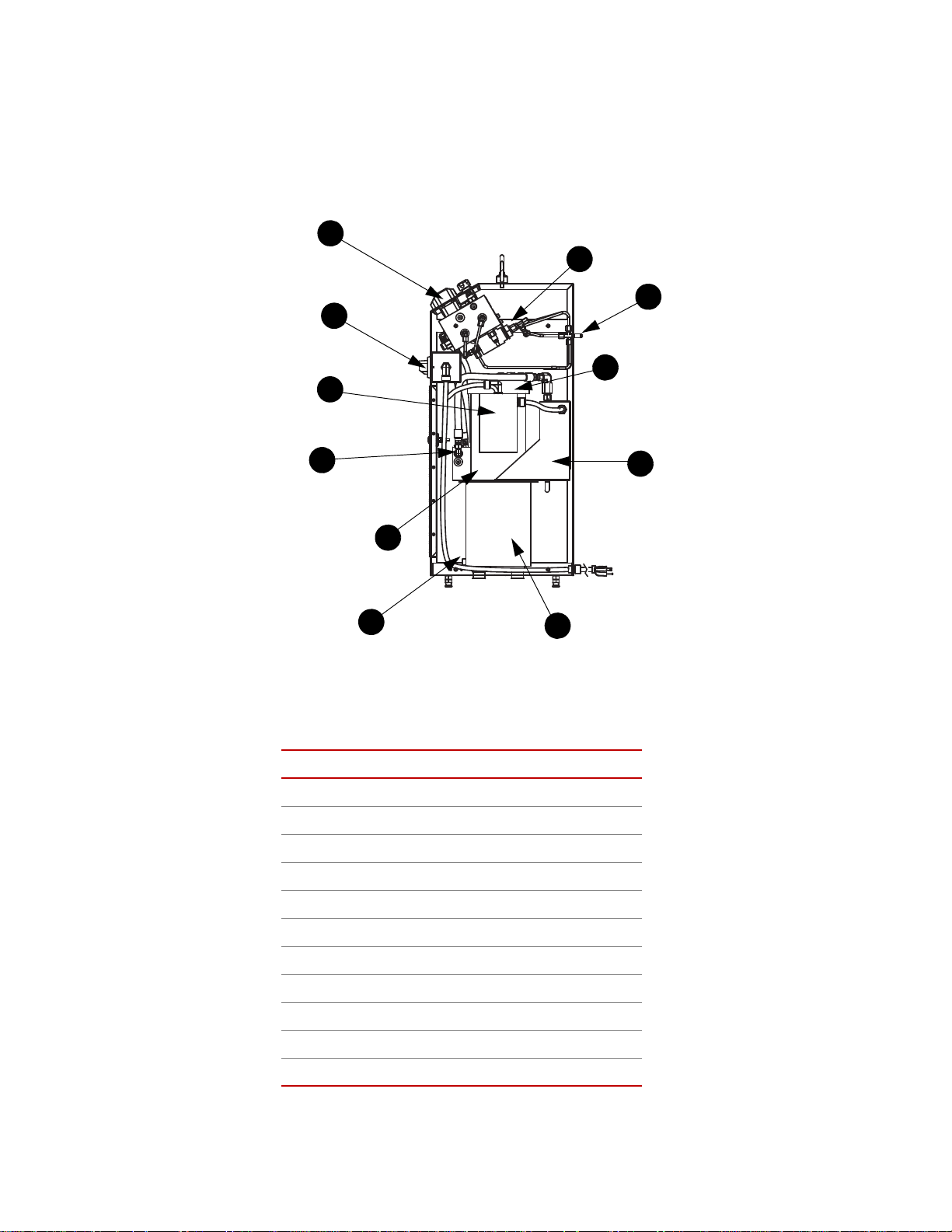
Series 685 Grip Supply Component Identification
Right Side
1
2
3
4
5
6
11
10
9
8
7
Series 685 Grip Supply Component Identification
Use the following figure to identify the components referenced in this manual.
Component Identification
TEM COMPONENT
I
1 Control Manifold
2
Power Switch Assembly
Introduction
14
3
4
5
6
7
8
9
10
11
Motor/Pump Assembly
Supply Manifold
NPT Plug/Breather
Drain Plug
Hydraulic Fluid Reservoir
Heat Exchanger
Hydraulic Fluid Filter (other side)
Grip Connections
Intensifiers
Series 685 Grip Supply Product Information
Page 15

Series 685 Grip Supply Functional Description
Series 685 Hydraulic Grip Supplies are designed to provide the hydraulic
pressure and grip control for specimen grips. All of the grip supplies include the
following features:
• Hydraulic flow control determines how fast the grips operate.
• Each grip has an independent pressure control valve. Each model has a
different adjustment range.
• Each of the two grips has an independent grip/release control.
Model 685.10 The Model 685.10 Hydraulic Grip Supply includes a self-contained hydraulic
system. Only electrical power is needed for continuous operation. The hydraulic
pressure can be adjusted between 7 MPa (1000 psi) and adjusted up to the rated
output 70 MPa (10,000 psi).
Model 685.22 The Model 685.22 Hydraulic Grip Supply includes a self-contained hydraulic
system. Only electrical power is needed for continuous operation. The hydraulic
pressure can be adjusted between 0.7 and 20.7 MPa (100 and 3000 psi).
Series 685 Grip Supply Functional Description
Model 685.60 The Model 685.60 Hydraulic Grip Supply uses the hydraulic power unit (HPU)
installed in your lab. The grip supply is factory rated for 45 MPa (6500 psi) or 68
MPa (10,000 psi). The output pressure can be adjusted up to the rated output.
Hydraulic power unit The Model 685.10 and Model 685.22 Hydraulic Grip Supplies have a self-
contained hydraulic system. The Model 685.60 Hydraulic Grip Supply gets its
hydraulic pressure from the hydraulic power unit in the lab.
The self-contained units include a reservoir for the hydraulic fluid and a motor
that drives a pump. The pump draws the hydraulic fluid from the reservoir
through a strain filter. The hydraulic fluid is pumped to the pressure manifold
where the pump pressure is regulated. When the hydraulic fluid is returned to the
reservoir, it is run through a cooler and a 10-micron filter.
Supply manifold The supply manifold includes two pressure reducing valves and a pressure gage.
One of the pressure reducing valves establishes the output pressure of the pump
(each model is set to a different pressure). The other is used as a relief valve that
is set 1.7 MPa (250 psi) higher than the pump’s output pressure. In the event the
output pressure exceeds the relief valve setting, the excess hydraulic pressure is
shunted to the return line. The output is sent to the control manifold.
Control manifold The control manifold outputs the hydraulic control to the grips. The control
manifold includes all of the front panel controls. All three models use the same
front panel controls.
Intensifier The Model 685.10 and Model 685.60 Hydraulic Grip Supplies include two oil-to-
oil hydraulic intensifiers. These devices multiply the input pressure by a factor of
four to obtain a higher output pressure.They are located on the control manifold.
Rate control The Rate control is a needle valve that restricts the hydraulic flow. This
adjustment determines how fast the grips clamp and unclamp.
Important The rate setting will be different for all grip sizes. You should be
sure to change this setting whenever you change grip sizes.
Series 685 Grip Supply Product Information Introduction
15
Page 16

Series 685 Grip Supply Hydraulic Schematics
Pressure control The Pressure control establishes the final output pressure to the grips. It works in
conjunction with another pressure reducing valve which is being used as a
pressure relief valve. These two valves work in the same fashion as the valves on
the supply manifold.Each Grip has its own independent pressure control valve
and safety relief valve.
Grip control The grip controls port the final output pressure to the grips. Each grip has two
port: a grip port and a release port. The grip controls change the output pressure
from the grip port to the release port and vice versa. The controls also have a
midpoint where the hydraulic pressure is stopped at the grip control; this causes
the grip to stop its hydraulic movement.
Series 685 Grip Supply Hydraulic Schematics
The following figures show the hydraulic schematic of each grip supply.
16
Introduction
Model 685.10 Hydraulic Schema tic
Series 685 Grip Supply Product Information
Page 17

Series 685 Grip Supply Hydraulic Schematics
Model 685.22 Hydraulic Schema tic
Series 685 Grip Supply Product Information Introduction
17
Page 18

Series 685 Grip Supply Specifications
Model 685.60 Hydraulic Schema tic
Series 685 Grip Supply Specifications
Refer to the Product Data Sheet for specifications. Force ratings, weights,
dimensions, and operating specifications can be found in the 685 Hydraulic Grip
Supplies & Intensifiers brochure on the MTS web site (www.mts.com
keyword “685”.
); search
18
Introduction
Series 685 Grip Supply Product Information
Page 19

Safety
General Safety Practices
Typically, grips and fixtures are part of equipment used in MTS testing systems.
This section provides general information about safety issues that pertain to
systems that use grips and fixtures. These issues include statements to the
intended use and foreseeable misuse of the system and definition for the
graphical hazard labeling that is affixed to your product, and other (more general)
safety information that relates to the high-pressure and high-performance
characteristics of MTS servohydraulic and electromechanical systems.
When you prepare to operate a system that includes grips or fixtures, ensure the
following:
• Do not use or allow personnel to operate the system who are not
General Safety Practices
experienced, trained, or educated in the inherent dangers associated with
high-performance servohydraulics and who are not experienced, trained, or
educated with regard to the intended operation as it applies to this test
system.
• Do not disable safety components or features (including limit detectors,
light curtains, or proximity switches/detectors).
• Do not attempt to operate the system without appropriate personal safety
gear (for example, hearing, hand, and eye protection).
• Do not modify the system or replace system components using parts that are
not MTS component parts or effect repairs using parts or components that
are not manufactured to MTS specifications.
• Do not operate the grips or fixtures in an explosive atmosphere.
• Do not use the system in a test area where uncontrolled access to the test
system is allowed when the system is in operation.
• For servohydraulic systems, do not operate the system unless an interlock is
installed to monitor supply pressure into the HSM and initiate a system
interlock if a low or no pressure event occurs.
If you have system related responsibilities (that is, if you are an operator, service
engineer, or maintenance person), you should study safety information carefully
before you attempt to perform any test system procedure.
You should receive training on this system or a similar system to ensure a
thorough knowledge of your equipment and the safety issues that are associated
with its use. In addition, you should gain an understanding of system functions
by studying the other manuals supplied with your test system. Contact MTS for
information about the content and dates of training classes that are offered.
It is very important that you study the following safety information to ensure that
your facility procedures and the system’s operating environment do not
contribute to or result in a hazardous situation. Remember, you cannot eliminate
all the hazards associated with this system, so you must learn and remain aware
Series 685 Grip Supply Product Information Safety
19
Page 20

General Safety Practices
of the hazards that apply to your system at all times. Use these safety guidelines
to help learn and identify hazards so that you can establish appropriate training
and operating procedures and acquire appropriate safety equipment (such as
gloves, goggles, and hearing protection).
Each test system operates within a unique environment which includes the
following known variables:
• Facility variables (facility variables include the structure, atmosphere, and
utilities)
• Unauthorized customer modifications to the equipment
• Operator experience and specialization
• Test specimens
Because of these variables (and the possibility of others), your system can
operate under unforeseen circumstances that can result in an operating
environment with unknown hazards.
Improper installation, operation, or maintenance of your system can result in
hazardous conditions that can cause death, personal injury, or damage to the
equipment or to the specimen. Common sense and a thorough knowledge of the
system’s operating capabilities can help to determine an appropriate and safe
approach to its operation.
Read all manuals Study the contents of this manual and the other manuals provided with your
system before attempting to perform any system function for the first time.
Procedures that seem relatively simple or intuitively obvious may require a
complete understanding of system operation to avoid unsafe or dangerous
situations.
Locate and read
hazard placards/labels
Know facility safe
procedures
Find, read, and follow the hazard placard instructions located on the equipment.
These placards are placed strategically on the equipment to call attention to areas
such as known crush points, electrical voltage, and high pressure hazards.
Most facilities have internal procedures and rules regarding safe practices within
the facility. Be aware of these safe practices and incorporate them into your daily
operation of the system.
Know controls Before you operate the system for the first time, make a trial run through the
operating procedures with the power off. Locate all hardware and software
controls and know what their functions are and what adjustments they require. If
any control function or operating adjustment is not clear, review the applicable
information until you understand it thoroughly.
Know specimen
properties
The user is responsible for understanding the characteristics of the test specimen.
Be sure to use appropriate personal protective equipment (clothing, hand gloves,
eye protection, and so forth.).
Use protective guards such as cages, enclosures, and special laboratory layouts
when you work with hazardous test specimens (for example, brittle or
fragmenting materials or materials that are internally pressurized).
20
Safety
Series 685 Grip Supply Product Information
Page 21

General Safety Practices
Specimen properties should also be taken into account when determining grip
pressure.
Have first aid available Accidents can happen even when you are careful. Arrange your operator
schedules so that a properly trained person is always close by to render first aid.
In addition, ensure that local emergency contact information is posted clearly and
in sight of the system operator.
Keep bystanders
safely away
Keep bystanders at a safe distance from all equipment. Never allow bystanders to
touch specimens or equipment while the test is running.
Wear proper clothing Do not wear neckties, shop aprons, loose clothing or jewelry, or long hair that
could get caught in equipment and result in an injury. Remove loose clothing or
jewelry and restrain long hair.
Remove flammable
fluids
Check bolt ratings and
torques
Remove flammable fluids from their containers or from components before you
install the container or component. If desired, you can replace the flammable
fluid with a non-flammable fluid to maintain the proper proportion of weight and
balance.
To ensure a reliable product, fasteners (such as bolts and tie rods) used in MTSmanufactured systems are torqued to specific requirements. If a fastener is
loosened or the configuration of a component within the system is modified, refer
to information in this product manual to determine the correct fastener, fastener
rating, and torque. Overtorquing or undertorquing a fastener can create a
hazardous situation due to the high forces and pressures present in MTS test
systems.
On rare occasions, a fastener can fail even when it is correctly installed. Failure
usually occurs during torquing, but it can occur several days later. Failure of a
fastener can result in a high velocity projectile. Therefore, it is a good practice to
avoid stationing personnel in line with or below assemblies that contain large or
long fasteners.
Practice good
housekeeping
Do not exceed the
Maximum Supply
Pressure
Do not disable safety
devices
Provide adequate
lighting
Provide means to
access out-of-reach
components
Series 685 Grip Supply Product Information Safety
Keep the floors in the work area clean. Hydraulic fluid that is spilled on any type
of floor can result in a dangerous, slippery surface. Do not leave tools, fixtures,
or other items not specific to the test, lying about on the floor, system, or decking.
For hydraulic grips and fixtures. make sure that the hydraulic supply pressure is
limited to the maximum pressure defined by the grip or fixture identification (ID)
tag.
Your system may have active or passive safety devices installed to prevent
system operation if the device indicates an unsafe condition. Do not disable such
devices as it may result in unexpected system motion.
Ensure adequate lighting to minimize the chance of operation errors, equipment
damage, and personal injury. You need to see what you are doing.
Make sure you can access system components that might be out of reach while
standing on the floor. For example, ladders or scaffolding might be required to
reach load cell connectors on tall load units.
21
Page 22

General Safety Practices
Wear appropriate
personal protection
Handle chemicals
safely
Know system
interlocks
Wear eye protection when you work with high-pressure hydraulic fluid,
breakable specimens, or when anything characteristic to the specimen could
break apart.
W ear ear protection when you work near electric motors, pumps, or other devices
that generate high noise levels. Some systems can create sound pressure levels
that exceed 70 dbA during operation.
W ear appropriate personal protection equipment (gloves, boots, suits, respirators)
whenever you work with fluids, chemicals, or powders that can irritate or harm
the skin, respiratory system, or eyes.
Whenever you use or handle chemicals (for example, cleaning fluids, hydraulic
fluid, batteries, contaminated parts, electrical fluids, and maintenance waste),
refer to the appropriate MSDS documentation for that material and determine the
appropriate measures and equipment required to handle and use the chemical
safely. Ensure that the chemical is disposed of appropriately.
Interlock devices should always be used and properly adjusted. Interlock devices
are designed to minimize the chance of accidental damage to the test specimen or
the equipment. Test all interlock devices for proper operation immediately before
a test. Do not disable or bypass any interlock devices as doing so could allow
hydraulic pressure to be applied regardless of the true interlock condition. The
Reset/Override button is a software function that can be used to temporarily
override an interlock while attempting to gain control of the system.
Know system limits Never rely on system limits such as mechanical limits or software limits to
protect you or any personnel. System limits are designed to minimize the chance
of accidental damage to test specimens or to equipment. T est all limits for proper
operation immediately before a test. Always use these limits and adjust them
properly.
Do not disturb sensors Do not bump, wiggle, adjust, disconnect, or otherwise disturb a sensor (such as
an accelerometer or extensometer) or its connecting cable when hydraulic
pressure is applied.
Ensure secure cables Do not change any cable connections when electrical power or hydraulic pressure
is applied. If you attempt to change a cable connection while the system is in
operation, an open control loop condition can result. An open control loop
condition can cause a rapid, unexpected system response which can result in
severe personal injury, death, or damage to equipment. Also, ensure that all
cables are connected after you make any changes in the system configuration.
Stay alert A void long periods of work without adequate rest. In addition, avoid long periods
of repetitious, unvarying, or monotonous work because these conditions can
contribute to accidents and hazardous situations. If you are too familiar with the
work environment, it is easy to overlook potential hazards that exist in that
environment.
Trapped pressure Take care when removing hoses. Pressure can remain; even with no system
pressure.
Contain small leaks Do not use your fingers or hands to stop small leaks in hydraulic or pneumatic
hoses. Substantial pressures can build up, especially if the hole is small. These
22
Safety
Series 685 Grip Supply Product Information
Page 23

Hazard Placard Placement
high pressures can cause the oil or gas to penetrate your skin, causing painful and
dangerously infected wounds. Turn off the hydraulic supply and allow the
hydraulic pressure to dissipate before you remove and replace the hose or any
pressurized component.
Stay clear of moving
equipment/avoid crush
points
Know the causes of
unexpected actuator
motions
Stay clear of mechanical linkages, connecting cables, and hoses that move
because you can get pinched, crushed, tangled, or dragged along with the
equipment. High forces generated by the system can pinch, cut, or crush anything
in the path of the equipment and cause serious injury. Stay clear of any potential
crush points. Most test systems can produce sudden, high-force motion. Never
assume that your reactions are fast enough to allow you to escape injury when a
system fails.
The high force and velocity capabilities of MTS actuators can be destructive and
dangerous (especially if actuator motion is unexpected). The most likely causes
of unexpected actuator response are operator error and equipment failure due to
damage or abuse (such as broken, cut, or crushed cables and hoses; shorted wires;
overstressed feedback devices; and damaged components within the servocontrol
loop). Eliminate any condition that could cause unexpected actuator motion.
Hazard Placard Placement
Hazard placards contain specific safety information and are affixed directly to the
system so they are plainly visible.
Each placard describes a system-related hazard. When possible, international
symbols (icons) are used to graphically indicate the type of hazard and the
placard label indicates its severity. In some instances, the placard may contain
text that describes the hazard, the potential result if the hazard is ignored, and
general instructions about how to avoid the hazard.
The following labels are typically located on the grip supply.
Series 685 Grip Supply Product Information Safety
23
Page 24

Hazard Placard Placement
Hydraulic Grip Supply
Model No.
Serial No.
Assembly No.
Working Pressure
Rev.
MTS Systems Corporation
14000 Technology Drive
Eden Prairie, MN U.S.A. 55344-2247
PN 477266-01
Supply Rating
Full Load Current
Manufacture Date
MPa
psi
VAC Hz
phase
amps
LABEL DESCRIPTION
Hydraulic Grip Supply ID label.
Contains the following information:
• Model number
• Serial number
• Assembly number/revision
• Working pressure
• Supply rating
Part #047-726-601
Part # 0484746xx
• Full load current
• Manufacture date
WARNING
Hydraulic pressure beyond rated working
pressure can rupture components. Can cause
severe personal injury and damage to
equipment.
Do not exceed rated working pressure of
grips or hoses.
Read manual instructions for pressure
adjustment procedure.
Note Hydraulic pressure warning label
part number depends on pressure
rating.
• 048-474-601—3000 psi/21 MPa
• 048-474-603—6500 psi/45 MPa
• 048-474-604—10,000 psi/69 MPa
Read the manuals.
24
Safety
Part #572376-01
Series 685 Grip Supply Product Information
Page 25

L
ABEL DESCRIPTION
Wear eye protection.
Part #572376-06
Lift point.
Part #572376-13
High fluid pressure
Hazard Placard Placement
Part #572302-45
Part #572302-02
Part # 572377-11: Maintain Safe Pressure
Gage Label.
Part # 572385-12: Maintain Safe Pressure
Range Label 3000 psi.
Part # 572385-13: Maintain Safe Pressure
Range Label 6500 psi.
Part # 572385-12: Maintain Safe Pressure
Range Label 10,000 psi.
Electrical connection hazard
Series 685 Grip Supply Product Information Safety
25
Page 26

Power Loss Considerations
Power Loss Considerations
For Series 685 stand-alone grip supplies, fluid pressure is locked in the grip by
means of the direction control valve. If power fails, this valve will leak drops
until the pressure in the grip is relieved. Sudden motion of the grips causing a
specimen to fall out is not likely. But, over time the clamp load will be removed
and a baseplate mounted actuator piston rod will settle, causing the specimen to
pull out of the grip.
26
Safety
Series 685 Grip Supply Product Information
Page 27

Installation
WARNING
Important The information in this section is for reference only. The Series 685
Installing a Series 685 Hydraulic Grip Supply consists of making the hydraulic
hose connections to the upper and lower grips. The Model 685.10 and Model
685.22 Hydraulic Grip Supplies also need an electrical connection. The
following procedure assumes that the grips to be controlled by the hydraulic grip
supply have been properly installed on a load unit.
Lifting and Moving the Grip Supply
Force ratings, weights, dimensions, and operating specifications can be found in
the Series 685 Hydraulic Grip Supplies & Intensifiers brochure on the MTS web
site (www.mts.com
Important For European Union (EU) countries, all lifting accessories (chains,
Lifting and Moving the Grip Supply
Grip Supply should only be installed by a qualified MTS Field
Service Engineer.
); search keyword “685”.
slings, hooks, rings, and so forth) that come between the MTSsupplied equipment and the customer supplied lifting system need
certification. Lifting accessories used in EU countries must be CE
marked.
This section describes how to lift and move the grip supply.
You will need a fork lift or overhead crane capable of lifting the grip supply.
Ensure that the lifting equipment can accommodate the weight of the grip supply .
The grip supply is heavy.
The weight of the grip supply can seriously hurt you and damage your grip
supply.
Do not allow the grip supply to drop or topple.
Make sure that your chains, slings, and crane have a working capacity greater
than the grip supply’s weight (see the preceding table).
Make sure that the hoist rings are tight.
Lift the grip supply only high enough to clear its pallet.
Operate the crane or forklift smoothly to prevent breaking shocks to the sling.
Series 685 Grip Supply Product Information Installation
27
Page 28

Lifting and Moving the Grip Supply
1. Unpack the grip supply.
A. Remove the grip supply from the shipping container (if used).
B. Remove any protective wrap ping.
C. Use a clean cloth to wipe dust or debris deposited during shipment.
2. Inspect the grip supply for shipping damage.
Look for the following:
• Scratches in the grip supply
• Damaged electrical connections
• Damaged hydraulic connections
• Dents and other structural damage
Report any damage found to both the carrier and MTS. In the U.S. and
Canada, call the MTS Call Center at 1-800-328-2255. Elsewhere, contact
your local MTS office.
3. Before you move the grip supply, check the following:
• The floor where the grip supply will sit can bear its weight.
• The path to where the grip supply will sit is clear and uncluttered.
• Plan a route that will accommodate the dimensions of the grip supply
with extra space for clearance through doors, hallways, and so forth.
• The area where the grip supply will sit is clean and well lit, with all
hoses and cables moved out of the way.
28
Installation
Series 685 Grip Supply Product Information
Page 29

4. Move the grip supply.
WARNING
Each
connection
is labeled
This illustration shows the
connections you need to make
when you install the hydraulic
grip supply.
The grip supply can be moved on its pallet with a fork lift or it can be
moved with its lifting hoist rings.
Lift the grip supply only as high as necessary, and move it slowly to the
installation site.
5. Remove the chains/slings.
6. If necessary, secure the grip supply.
The grip supply can be secured to an adequate foundation. The base of the
grip supply has a hole in each corner; diameter 13.48 mm (0.531 in). Refer
to the drawings for spacing requirements.
7. Contact MTS Systems Corporation to arrange for installation services.
In the U.S. and Canada, call the MTS Call Center at 1-800-328-2255.
Elsewhere, contact your local MTS office.
Series 685 Grip Supply Installation Procedure
Series 685 Grip Supply Installation Procedure
Under-rated hoses can rupture.
Ruptured hoses can cause injury to personnel or damage to equ ip ment.
Do not use hydraulic hoses rated for less than 69 MPa (10,000 psi) for the 685.10
and 685.60 or 21 MPa (3000 psi) for the 685.22. Use only hy draulic hoses that
have a working pressure greater than 69 MPa (10,000 psi).
Series 685 Grip Supply Product Information Installation
29
Page 30

Series 685 Grip Supply Installation Procedure
CAUTION
Cooling Fan Motor
Hydraulic Pump Motor
On/Off Switch
Ground
Note: All local codes override
the wiring diagram and
matrix table.
If you are installing a Model 685.10 or Model 685.22 Hydraulic Grip Supply,
turn the power switch to the Off position.
1. Position the hydraulic grip supply.
Locate the grip supply close to the load unit so that you can reach both grips
(for specimen installation) and you can operate the hydraulic grip supply.
If it is not possible to do this due to the size of the load unit or other physical
reasons, position the hydraulic grip supply to provide the maximum
convenience.
Be sure to connect hoses to the correct ports.
Connecting hoses to the wrong ports can cause unexpected grip movement and
equipment damage.
2. Connect the hydraulics.
The remaining steps apply
only to the Model 685.10
and Model 685.22
Hydraulic Grip Supplies.
A. Remove the caps from the four ports on the rear of the hydraulic grip
supply and connect hydraulic hoses.
B. Connect the other ends of the hydraulic hoses to the corresponding
fittings on the upper and lower grips.
3. Configure the power connection.
The appropriate connector for your local service should be included with the
hydraulic grip supply. If the power cord is not connected, use the following
figure to assist you in connecting the power cord.
Plug the unit power cord into the appropriate power source.
30
Installation
CUSTOMER-SUPPLIED POWER L1 L2
115 V / 60 Hz / 1 phase 115 V Common
208 V/ 60 Hz / 1 phase 104 V 104 V
230 V / 60 Hz / 1 phase 115 V 115 V
Series 685 Grip Supply Product Information
Page 31

Series 685 Grip Supply Installation Procedure
Sight gage
NPT/Breather
CUSTOMER-SUPPLIED POWER L1 L2
100 V / 50 Hz / 1 phase 100 V Common
110 V / 50 Hz / 1 phase 110 V Common
200 V / 50 Hz / 1 phase 200 V Common
220 V / 50 Hz / 1 phase 220 V Common
240 V / 50 Hz / 1 phase 240 V Common
4. Remove the 1/2 inch NPT plug.
The plug was installed in the top of the reservoir for shipment from the
factory.
Series 685 Grip Supply Product Information Installation
5. Check the fluid in the reservoir.
The reservoir contains 8.3 liters (2.2 gallons) when the fluid is up to the
“High” mark on the sight gage and 6.1 liters (1.6 gallons) when the level is
at the “Low” mark.
Add fluid to the reservoir as necessary to bring the fluid level to or near the
“High” mark on the sight gage. An extra gallon is shipped with the
hydraulic grip supply. Never add another fluid other than Mobil 525 SHC to
the reservoir.
6. Install the breather.
31
Page 32

Series 685 Grip Supply Installation Procedure
CAUTION
The breather is taped to the manifold behind the front access door during
shipment of the unit. Install it in the 1/2 inch NPT hole in the top of the
reservoir.
Closing the grip without a specimen inserted or with a specimen only
partially inserted may damage grips.
Do not clamp the grips without a specimen installed. See the appropriate grip
product information manual for detailed specimen mounting instructions.
7. Check the grip operation.
A. Set both grip controls to the release position.
B. Turn the power switch to the On position.
C. Change the grip control s between grip and release a few times and
check for leaks at all connections (correct as needed).
D. With the grips fully released, check the level of the hydraulic fluid in
the reservoir.
If the fluid level has dropped below the “Low” level, add fluid as
necessary.
E. Turn the power switch to the Off position.
32
Installation
Series 685 Grip Supply Product Information
Page 33

Operation
Contents Series 685 Grip Supply Controls and Indicators 33
Series 685 Grip Supply Controls and Indicators
This section describes how to use the hydraulic grip supply. Some operating
details depend on the particular grips you have. You should have your grip
manual available for specimen installation and removal procedures.
Determining the Grip Operating Pressure 35
How to Adjusting the Output Pressure 35
About Rate Control 36
How to Grip a Specimen 37
How to Remove a Specimen from Grips 38
How to Recover from a Thermal Overload 39
Note The hydraulic grip supply is not part of the system interlock chain. If you
detect a problem with the hydraulic grip supply, turn it off using the On/
Off switch located on the front of the Model 685.xx chassis.
Series 685 Grip Supply Controls and Indicators
Series 685 Grip Supply Product Information Operation
33
Page 34

Series 685 Grip Supply Controls and Indicators
Unless otherwise noted, the controls and indicators are located on the following
control panel figure.
1
2
3
4
I
TEM CONTROL DESCRIPTION
On/Off
(located on the
front of the Model
685.10 and Model
Applies electrical power to the hydraulic grip supply.
With the switch lever in the On position, power is applied to the unit. When the
pump motor and cooling fan are running, hydraulic pressure is available for
grip operation.
685.22 chassis)
1 Pressure Gages
Show the current hydraulic pressure setting for grip operation. Two gages are
used: one for the upper grip and one for the lower grip.
The gages includes scales for both Bar and psi units.
Use the gages while adjusting the Pressure control to achieve the desired
clamping pressure. See the grip manual for gripping pressures.
2Rate
Adjusts how fast the grips clamp and unclamp.
Adjust the Rate control clockwise to slow the clamping of the specimen.
Otherwise, adjust the Rate control counterclockwise to increase the clamping
speed.
Important Different grips require different clamp and unclamp rates; be
sure to adjust the Rate control whenever you change grips.
34
Operation
Series 685 Grip Supply Product Information
Page 35

I
TEM CONTROL DESCRIPTION
Determining the Grip Operating Pressure
3 Pressure control
4 Grip Controls
Adjusts the amount of hydraulic pressure applied to the grips to grip the
specimen. There is a valve for the upper grip and another valve for the lower
grip.
These are multi-turn valves. Pressure increases as the knob is turned clockwise
and decreases as the knob is turned counterclockwise. The adjustment range
depends on the model number of the hydraulic grip supply.
To determine the correct operating pressure, see “Adjusting the Output
Pressure.”
Controls are provided for the upper grip and lower grip for specimen
installation and removal. The three-position controls can grip or release one
end of a specimen.
Indicators are provided to show the grip control position. Turn the control
clockwise to clamp a specimen into the grip. Turn the control
counterclockwise to release a specimen from the upper grip. The gripping
action can be stopped at a detent between grip and ungrip by moving the
control midway between the two grip symbols.
Determining the Grip Operating Pressure
You must consider the following factors to determine the appropriate grip
operating pressure:
• The type of grips to be used
• The specimens to be tested
• The tests to be performed
• The model number of the grip supply
Grip manuals (from MTS) describe how to determine the required operating
pressure. They include formulas or graphs to determine the grip pressure (also
called minimum operating pressure). The minimum pressure, as referred to in the
grip manual, is the calculated least pressure that will provide adequate gripping
of the specimen while it is being tested at specific maximum loads.
If practice indicates that the calculated pressure proves to be too low (because the
specimen slips under load due to hardness or other characteristics), then the
actual minimum pressure will have to be increased to provide adequate gripping.
Use the grip manual to determine the minimum grip operating pressure that is
best for the test situation at hand.
The grip supply can be configured to produce different output pressures. Check
the model number specification. See “Adjusting the Output Pressure” for the
procedure.
How to Adjusting the Output Pressure
The output pressure of the hydraulic grip supply determines the gripping force
applied to the specimen by the grips. The output pressure can be adjusted up to
Series 685 Grip Supply Product Information Operation
35
Page 36

About Rate Control
the maximum output pressure of the hydraulic grip supply. The maximum output
pressure is different for each model:
• The maximum output pressure of the Model 685.10 and Model 685.60
Hydraulic Grip Supplies can be factory set to 45 MPa (6500 psi) or 68 MPa
(10,000 psi).
• The maximum output pressure of the Model 685.22 Hydraulic Grip Supply
is 21 MPa (3000 psi).
1. Determine the required grip operating pressure.
See “Determining the Grip Operating Pressure” and also see the grip
manual.
2. Install the specimen and turn both grip controls to the grip position
(clockwise).
3. Make sure that the hydraulic grip supply is turned on.
Note If this procedure is being performed for the first time since the hydraulic
grip supply was installed, make sure that the 1/2 inch NPT plug was
removed from the top of the reservoir and that the breather was installed
in its place.
About Rate Control
4. Set the operating pressure.
Turn the Pressure control to obtain the desired operating pressure as shown
on the control panel pressure gage for both grips.
5. If you exceed the desired pressure, perform one of the following:
• For the Model 685.22 Hydraulic Grip Supply, turn the Pressure control
counterclockwise 1/2 turn, and then return to Step 4.
• For the Model 685.10 and Model 685.60 Hydraulic Grip Supplies, turn
the Pressure control counterclockwise 1/2 turn, and cycle the grip
controls by clamping and unclamping the grip. Then return to Step 4.
The Rate control may be adjusted at any time. If the grips move too fast to suit
your personal preference, turn the Rate control clockwise to slow the speed of
grip action. Turning the Rate control counterclockwise speeds up grip action.
Turning the Rate control fully clockwise stops the flow of fluid to the grips. If
the grips do not operate, check to be sure that the Rate control has not been
turned fully clockwise.
Adjustment of rate is a matter of personal preference. It should be based on the
desired speed of grip action during the gripping and ungripping processes. (The
speed of grip action is dependent both on the adjustment of the rate control and
the particular grips being used.)
36
Operation
When first operating the grips, use a slower speed (lower rate setting). Then
increase the operating speed to your satisfaction.
Important Different grips require different clamp and unclamp rates; be sure
to adjust the Rate control whenever you change grips.
Series 685 Grip Supply Product Information
Page 37

How to Grip a Specimen
WARNING
CAUTION
Prerequisite This procedure assumes that the output pressure has been adjusted.
How to Grip a Specimen
Have the appropriate grip manual handy for more specific specimen mounting
information.
Do not put anything in a crush zone when turning on hydraulic power.
Unexpected actuator movement can occur when hydraulic pressure is
turned on. This can cause personal injury or equipment damage.
Be sure you read and understand all safety information provided with your
system. Follow all applicable system operating procedures before turning on
hydraulic power.
Before turning on hydraulic power, first make sure that all systems or equipment
that use the same hydraulic power source are in appropriate condition for
application of hydraulic power.
1. Select a force control mode to control the actuator.
Select force control at the system controller and use the most sensitive
(lowest load) range available.
If your controller has a channel-limited-channel control mode for specimen
installation, use one defined with displacement control and force limiting.
2. Release the grips.
Make sure that both grip controls are in the release position.
3. Turn on electrical power.
This only applies to the Model 685.10 and Model 685.22 Hydraulic Grip
Supplies. Turn the power switch to the On position.
4. Apply full system hydraulic pressure.
Use applicable system procedures to turn on the system hydraulic pressure.
Do not clamp the grips without a specimen installed.
Some grips may be damaged by closing the grip without a specimen
inserted or with a specimen only partially inserted.
See the appropriate grip product information manual for detailed specimen
mounting instructions.
5. To grip the specimen:
Series 685 Grip Supply Product Information Operation
37
Page 38

How to Remove a Specimen from Grips
WARNING
Because of the large variety of load frame, grip, and controller equipment in
use, it is impossible to give explicit instructions for this process.
Pliers or tong-like tools, such as those used for installing or removing
cartridge-type electrical fuses, are often used for holding small specimens in
proper position within the grips to lessen the possibility of having fingers
pinched or crushed during the gripping process.
Gripping a specimen typically involves manually placing the specimen
within the upper grip and then, with the specimen correctly in place,
applying hydraulic gripping pressure to the upper grip. Then, the actuator
must be positioned to grip the lower portion of the specimen before
hydraulic gripping pressure is applied.
A. Perform any operations necessary to correctly position one end of the
B. When the specimen is properly positioned within the upper grip, rotate
C. Perform any operations necessary to correctly position one end of the
specimen within the upper grip.
the upper grip control clockwise to the grip position.
specimen within the lower grip.
D. When the specimen is properly positioned within the lower grip, rotate
the lower grip control clockwise to the grip position.
Note While applying test loads to specimens mounted in the grips, leave the
grip controls in the grip position and leave the hydraulic grip supply
turned on.
How to Remove a Specimen from Grips
To remove a specimen from the grips:
Do not put anything in a crush zone when turning on hyd ra ul ic pow er.
Heavy specimens or specimen fragments falling from the grips can injure
you or damage test equipment.
Take adequate precautions to support heavy specimens while releasing them
from the grips.
1. If needed, provide adequate support for the specimen, and turn the upper
grip control to the release position.
38
Operation
2. If the specimen is broken, remove the upper portion.
3. Determine whether it is necessary to reposition the crosshead or actuator to
provide adequate clearance for removal of the lower part of the specimen.
Reposition the crosshead or actuator, as needed.
4. If needed, provide adequate support for the specimen, and rotate the lower
grip control to the release position.
Series 685 Grip Supply Product Information
Page 39

5. Remove the specimen.
CAUTION
WARNING
6. This step applies to the Model 685.10 and Model 685.22 Hydraulic Grip
Supplies only. If you are finished using the hydraulic grip supply, turn the
power switch to the Off position.
How to Recover from a Thermal Overload
Note Recovering from a thermal overload only applies to the Model 685.10
and Model 685.22 Hydraulic Grip Supplies.
A thermal overload can cause the hydraulic grip supply to turn off unexpectedly.
To recover from a motor thermal overload:
Do not operate a hydraulic grip supply that has a recurring thermal overload
of the motor.
When the motor experiences a thermal overload, the motor stops and
hydraulic pressure to the grips decreases. This causes the grips to release.
If a test is underway, the specimen can break and damage your equipment.
How to Recover from a Thermal Overload
Contact your local MTS Service Representative.
1. Turn the power switch to the Off position.
2. Remove the panel on the left side of the chassis (see “Removing the Side
Panels”).
Do not touch the motor casing.
After prolonged operation, the motor casing may get hot enough to burn
your hand.
Do not touch the motor casing when pressing the motor reset button.
3. Locate the round, red reset button near the upper end of the motor.
4. Press the thermal reset button.
5. Set the upper and lower grip controls to the release position.
6. Turn the power switch to the On position to resume operation of the
hydraulic grip supply.
Series 685 Grip Supply Product Information Operation
39
Page 40

How to Recover from a Thermal Overload
40
Operation
Series 685 Grip Supply Product Information
Page 41

Maintenance
Contents Series 685 Grip Supply Maintenance Intervals 41
Series 685 Grip Supply Maintenance Intervals
This section describes the maintenance that is required to keep the hydraulic grip
supply in good operating condition. See “Component Identification” for the
location of the components described in this section.
Note Preventive maintenance is required only for the Model 685.10 and Model
685.22 Hydraulic Grip Supplies.
If service or overhaul procedures not described here are required to repair an
inoperative hydraulic grip supply, call your local MTS service representative.
Hydraulic Fluid Maintenance 42
Remove the Series 685 Grip Supply Side Panels 43
Clean the Heat Exchanger 43
Replace the Hydraulic Fluid Filter Element 43
Grip Supply Transport or Storage Preparation 44
Series 685 Grip Supply Maintenance Intervals
Maintenance items and intervals are shown in the following table.
Maintenance Schedule
M
AINTENANCE INTERVAL*
Check fluid level and replenish as required Daily
Inspect hoses for wear or leaks Daily
Check fluid quality/condition and replace if
necessary
Clean the heat exchanger Every 6 months
Replace fluid filter element Every 6 months
Clean fluid/air cooler fins Every 6 months
Replace hydraulic fluid
Clean pump inlet strainer Whenever replacing fluid
* The interval is based on an 8 hour a day, 5 days a week operation schedule. Dusty or dirty
environments require more frequent maintenance.
†
Replacing the hydraulic fluid is not considered a maintenance procedure. Due to the
extensive disassembly of the hydraulic power supply within the grip, it is considered a
service procedure.
†
Every 3 months
Yearly or sooner if poor condition is noted
Series 685 Grip Supply Product Information Maintenance
41
Page 42

Hydraulic Fluid Maintenance
CAUTION
Hydraulic Fluid Maintenance
Note Hydraulic fluid maintenance is required only for the Model 685.10 and
Model 685.22 Hydraulic Grip Supplies.
Checking the
fluid level
The reservoir has a built-in sight gage for checking the level of fluid in the
reservoir. When the 11.4 L (3.0 gal) reservoir is filled to the recommended level,
the sight gage will show fluid to the “HIGH” level on the gage and the reservoir
will contain 8.3 L (2.2 gal) of fluid.
Mixing different brands or types of hydraulic fluid can create contaminant s .
These contaminants will damage the hydraulic grip supply.
Do not mix different brands or types of hydraulic fluid in the hydraulic grip supply.
Use Mobil 525 SHC fluid only.
• Do not operate the hydraulic grip supply if fluid level is below the “LOW”
level on the gage. (The reservoir contains 6.1 l [1.6 gal] of fluid at the
“LOW” level.)
• Check the sight gage daily.
Fluid loss, if any, should be minimal and typically occurs only when hose
connections are opened to change grips or when removing samples for
checking the condition of the fluid.
Checking the hydraulic
fluid
Find and correct the cause of any unexplained fluid loss, and then fill the
reservoir to the “HIGH” level.
Check the condition of the hydraulic fluid every three months or any time the
fluid in the sight glass shows any sign of the conditions mentioned in the table
below.
Obtain a sample of fluid and check the following table. If any of the conditions
listed below are evident, replace both the hydraulic fluid and the hydraulic fluid
filter element. A fluid sample may be obtained by removing the breather from the
top of the reservoir and then siphoning fluid from the reservoir.
FLUID CONDITION DESCRIPTION
Dirty fluid
Chemical breakdown
Fresh hydraulic fluid is typically clear. Any change
in color (such as darkened fluid) indicates that it is
time to replace the fluid.
Considerable darkness, burnt odor, or an opaque
quality of the fluid indicates chemical breakdown.
42
Maintenance
Series 685 Grip Supply Product Information
Page 43

Remove the Series 685 Grip Supply Side Panels
F
LUID CONDITION DESCRIPTION
Water
Sediment
A milky appearance indicates water is present in
the fluid, usually from condensation.
Allow the sample to stand overnight, and then
check for sediment. Sediment at the bottom of the
sample indicates a collapsed, ruptured, or clogged
filter.
Remove the Series 685 Grip Supply Side Panels
Both side panels can be removed to provide better access for maintenance
procedures.
Each side panel is held in place by a screw which is located near the front feet of
the cabinet. These screws are installed to prevent the sides from moving during
shipment. Once they are removed, they need not be reinstalled unless you want to
transport the hydraulic grip supply (see “Preparing the Grip Supply for Transport
or Storage”).
Once the transport screws are removed, the side panels can be lifted and pulled
away from the chassis. The side panels mount to the chassis with slotted tabs that
mate with flanged pins. Each door has four slots.
Clean the Heat Exchanger
Note Cleaning the heat exchanger only applies to the Model 685.10 and
Model 685.22 Hydraulic Grip Supplies.
Clean the heat exchanger every six months.
• If the motor/pump/reservoir assembly is installed in the cabinet,
use a vacuum cleaner tool to remove dust and dirt from the fins of the heat
exchanger.
• If the motor/pump/reservoir assembly is outside the cabinet,
use a vacuum cleaner tool or compressed air to remove dust and dirt from
the fins of the heat exchanger.
Replace the Hydraulic Fluid Filter Element
Note Replacing the hydraulic fluid filter only applies to the Model 685.10 and
Model 685.22 Hydraulic Grip Supplies.
Replace the fluid filter element whenever replacing the hydraulic fluid, or every
six months. The filter is located behind the left side door (see “Component
Identification”).
The fluid filter uses a spin-on filter and may require a strap-type wrench for
removal. The MTS part number for the filter element is 114963-11. Use a drip
pan and rags to catch and wipe up fluid spilled during this procedure.
1. Turn the power switch to the Off position.
Series 685 Grip Supply Product Information Maintenance
43
Page 44

Grip Supply Transport or Storage Preparation
2. Remove the left side of the chassis (see “Removing the Side Panels”) to
access the filter.
3. Remove the filter element. Discard the old filter element and any fluid it
contains.
4. Wipe off the bottom seal surface of the filter head.
5. Apply clean hydraulic fluid (Mobil 525 SHC) to the seal on the new filter
element.
6. Screw on the new filter element and tighten it (hand-tight) only.
7. Turn the power switch to the On position.
8. Check for fluid leaks around the top of the filter element. If leaking, the
element may be tightened one additional quarter turn (you may need to use a
strap wrench).
Grip Supply Transport or Storage Preparation
If the hydraulic grip supply is to be disconnected from the grips, be sure to put
caps on the four -4 JIC fittings on the rear of the unit.
If the hydraulic grip supply will not be in use for an extended time period,
remove the breather on the reservoir and replace it with a 1/2 inch NPT plug.
This will help prevent contamination of the hydraulic fluid.
Install two screws removed in the procedure “Removing the Side Panels.” These
screws are only needed for transport services.
44
Maintenance
Series 685 Grip Supply Product Information
Page 45

Series 685 Grip Supply Product Information
45
Page 46

46
Series 685 Grip Supply Product Information
Page 47

Page 48

m
MTS Systems Corporation
14000 Technology Drive
Eden Prairie, Minnesota 55344-2290 USA
Toll Free Phone: 800-328-2255
(within the U.S. or Canada)
Phone: 952-937-4000
(outside the U.S. or Canada)
Fax: 952-937-4515
E-mail: info@mts.com
Internet: www.mts.com
ISO 9001 Certified QMS
 Loading...