

Page 1

be certain.
m
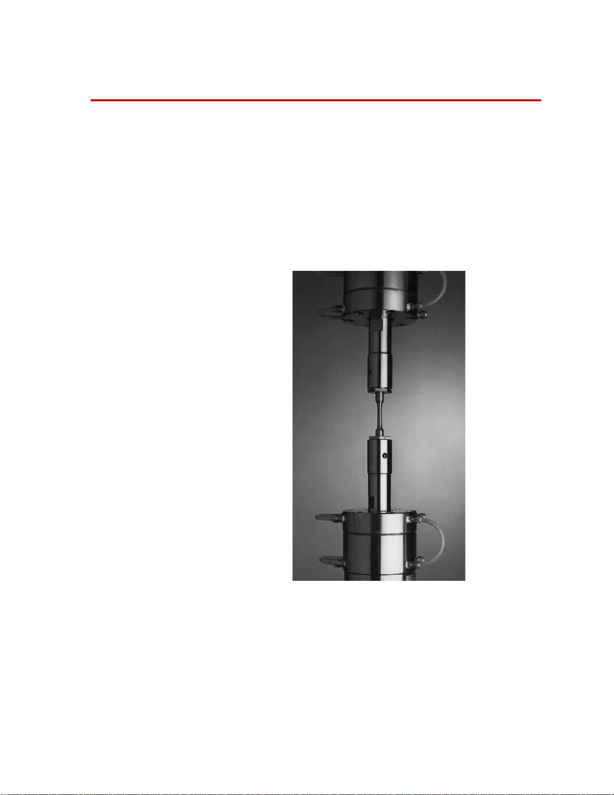
Model 680.01 High-Temperature Grips
Product Information
015-018-801 F
Page 2

Copyright information © 1991, 2001, 2002, 2008, 2009 MTS Systems Corporation. All rights reserved.
Trademark information MTS is a registered trademark of MTS Systems Corporation within the United
States. This trademark may be protected in other countries.
DTE and SHC are registered trademarks of Mobil Corporation. All other
trademarks or service marks are property of their respective owners.
Publication information
MANUAL PART NUMBER PUBLICATION DATE
015-018-801 A January 1991
015-018-801 B March 2001
015-018-801 C October 2002
015-018-801 D March 2008
015-018-801 E September 2008
015-018-801 F April 2009
Page 3

Contents
Technical Support 5
How to Get Technical Support 5
Before You Contact MTS 5
If You Contact MTS by Phone 6
Problem Submittal Form in MTS Manuals 7
Preface 9
Before You Begin 9
Conventions 10
Documentation Conventions 10
Introduction 13
Model 680.01 High-Temperature Grips Functional Description 14
Model 680.01 High-Temperature Grip Accessories 15
Model 680.01 High-Temperature Grips Specifications 17
Model 680.01 High-Temperature Grips Dimensions 18
Safety Information 19
Hazard Placard Placement 19
Installation 21
Install the Grips 22
Install the Hand-Operated Hydraulic Pump 25
Install the Cooling Kit 26
Preload the Spiral Washers 27
Grip Water Cooling Assembly Configurations for Servohydraulic Frames 29
Model 680.01 High-Temperature Grips Contents
3
Page 4

Operation 33
Determine the Gripping Pressure 33
Install Threaded Specimens 35
Install Button-End Specimens 37
Adjust the Water Flow 38
Remove Specimens from the Grips 39
Maintenance 41
Clean the Grips 41
Add Hydraulic Fluid to the Hand Pump 42
4
Contents
Model 680.01 High-Temperature Grips
Page 5

Technical Support
How to Get Technical Support
Start with your
manuals
Technical support
methods
MTS web site
www.mts.com
E-mail techsupport@mts.com
Telephone MTS Call Center 800-328-2255
Fax 952-937-4515
The manuals supplied by MTS provide most of the information you need to use
and maintain your equipment. If your equipment includes MTS software, look
for online help and README files that contain additional product inform ation.
If you cannot find answers to your technical questions from these sources, you
can use the internet, e-mail, telephone, or fax to contact MTS for assistance.
MTS provides a full range of support services after your system is installed. If
you have any questions about a system or product, contact MTS in one of the
following ways.
The MTS web site gives you access to our technical support staff by means of a
Technical Support link:
www.mts.com > Contact Us > Service & Technical Support
Weekdays 7:00 A.M. to 5:00 P.M., Central Time
Please include “Technical Support” in the subject line.
Before You Contact MTS
MTS can help you more efficiently if you have the following information
available when you contact us for support.
Know your site
number and system
number
Model 680.01 High-Temperature Grips
The site number contains your company number and identifies your equipment
type (material testing, simulation, and so forth). The number is usually written on
a label on your MTS equipment before the system leaves MTS. If you do not
have or do not know your MTS site number, contact your MTS sales engineer.
Example site number: 571167
When you have more than one MTS system, the system job number identifies
which system you are calling about. You can find your job number in the papers
sent to you when you ordered your system.
Example system number: US1.42460
5
Page 6

Know information from
prior technical
If you have contacted MTS about this problem before, we can recall your file.
You will need to tell us the:
assistance
• MTS notification number
• Name of the person who helped you
Identify the problem Describe the problem you are experiencing and know the answers to the
following questions:
• How long and how often has the problem been occurring?
• Can you reproduce the problem?
• Were any hardware or software changes made to the system before the
problem started?
• What are the model numbers of the suspect equipment?
• What model controller are you using (if applicable)?
• What test configuration are you using?
Know relevant
computer information
Know relevant
software information
If you are experiencing a computer problem, have the following information
available:
• Manufacturer’s name and model number
• Operating software type and service patch information
• Amount of system memory
• Amount of free space on the hard drive in which the application resides
• Current status of hard-drive fragmentation
• Connection status to a corporate network
For software application problems, have the following information available:
• The software application’s name, version number, build number, and if
available, software patch number. This information is displayed briefly
when you launch the application, and can typically be found in the “About”
selection in the “Help” menu.
• It is also helpful if the names of other non-MTS applications that are
running on your computer, such as anti-virus software, screen savers,
keyboard enhancers, print spoolers, and so forth are known and available.
If You Contact MTS by Phone
Your call will be registered by a Call Center agent if you are calling within the
United States or Canada. Before connecting you with a technical support
specialist, the agent will ask you for your site number, name, company , company
address, and the phone number where you can normally be reached.
6
Model 680.01 High-Temperature Grips
Page 7

If you are calling about an issue that has already been assigned a notification
number, please provide that number. You will be assigned a unique notification
number about any new issue.
Identify system type To assist the Call Center agent with connecting you to the most qualified
technical support specialist available, identify your system as one of the
following types:
• Electromechanical materials test system
• Hydromechanical materials test system
• Vehicle test system
• Vehicle component test system
• Aero test system
Be prepared to
Prepare yourself for troubleshooting while on the phone:
troubleshoot
• Call from a telephone when you are close to the system so that you can try
implementing suggestions made over the phone.
• Have the original operating and application software media available.
• If you are not familiar with all aspects of the equipment operation, have an
experienced user nearby to assist you.
Write down relevant
Prepare yourself in case we need to call you back:
information
• Remember to ask for the notification number.
• Record the name of the person who helped you.
• Write down any specific instructions to be followed, such as data recording
or performance monitoring.
After you call MTS logs and tracks all calls to ensure that you receive assistance and that action
is taken regarding your problem or request. If you have questions about the status
of your problem or have additional information to report, please contact MTS
again and provide your original notification number.
Problem Submittal Form in MTS Manuals
Use the Problem Submittal Form to communicate problems you are experiencing
with your MTS software, hardware, manuals, or service which have not been
resolved to your satisfaction through the technical support process. This form
includes check boxes that allow you to indicate the urgency of your problem and
your expectation of an acceptable response time. We guarantee a timely
response—your feedback is important to us.
The Problem Submittal Form can be accessed:
• In the back of many MTS manuals (postage paid form to be mailed to MTS)
• www.mts.com > Contact Us > Problem Submittal Form (electronic form to
be e-mailed to MTS)
Model 680.01 High-Temperature Grips
7
Page 8

8
Model 680.01 High-Temperature Grips
Page 9

Preface
Before You Begin
Safety first! Before you attempt to use your MTS product or system, read and understand the
Safety manual and any other safety information provided with your system.
Improper installation, operation, or maintenance of MTS equipment in your test
facility can result in hazardous conditions that can cause severe personal injury or
death and damage to your equipment and specimen. Again, read and understand
the safety information provided with your system before you continue. It is very
important that you remain aware of hazards that apply to your system.
Other MTS manuals In addition to this manual, you may receive additional MTS manuals in paper or
electronic form.
If you have purchased a test system, it may include an MTS System
Documentation CD. This CD contains an electronic copy of the MTS manuals
that pertain to your test system, including hydraulic and mechanical component
manuals, assembly drawings and parts lists, and op eration and preventive
maintenance manuals. Controller and application software manuals are typically
included on the software CD distribution disc(s).
Model 680.01 High-Temperature Grips
9
Page 10

Conventions
DANGER
WARNING
CAUTION
Conventions
Documentation Conventions
The following paragraphs describe some of the conventions that are used in your
MTS manuals.
Hazard conventions As necessary, hazard notices may be embedded in this manual. These notices
contain safety information that is specific to the task to be performed. Hazard
notices immediately precede the step or procedure that may lead to an associated
hazard. Read all hazard notices carefully and follow the directions that are given.
Three different levels of hazard notices may appear in your manuals. Following
are examples of all three levels.
Note For general safety information, see the safety information provided with
your system.
Danger notices indicate the presence of a hazard with a high level of risk which,
if ignored, will result in death, severe personal injury, or substantial property
damage.
Warning notices indicate the presence of a hazard with a medium level of risk
which, if ignored, can result in death, severe personal injury, or substantial
property damage.
Caution notices indicate the presence of a hazard with a low level of risk which,
if ignored, could cause moderate or minor personal injury, equipment damage, or
endanger test integrity.
Notes Notes provide additional information about operating your system or highlight
easily overlooked items. For example:
Note Resources that are put back on the hardware lists show up at the end of
the list.
Special terms The first occurrence of special terms is shown in italics.
Illustrations Illustrations appear in this manual to clarify text. It is important for you to be
Electronic manual
conventions
10
aware that these illustrations are examples only and do not necessarily represent
your actual system configuration, test application, or software.
This manual is available as an electronic document in the Portable Document
File (PDF) format. It can be viewed on any computer that has Adobe Acrobat
Reader installed.
Model 680.01 High-Temperature Grips
Page 11

Conventions
Hypertext links The electronic document has many hypertext links displayed in a blue font. All
blue words in the body text, along with all contents entries and index page
numbers, are hypertext links. When you click a hypertext link, the application
jumps to the corresponding topic.
Model 680.01 High-Temperature Grips
11
Page 12

Conventions
12
Model 680.01 High-Temperature Grips
Page 13
Introduction
Contents Model 680.01 High-Temperature Grips Functional Description 14
The MTS Model 680.01 High-Temperature Hydraulic Grips are used with a high
temperature furnace installed in a load unit for tension-compression testing of
metallic specimens at elevated temperatures. The grips can be heated at
temperatures up to 1000°C (1832°F).
Model 680.01 High-Temperature Grip Accessories 15
Model 680.01 High-Temperature Grips Specifications 17
Model 680.01 High-Temperature Grips Dimensions 18
What you need to
know
Model 680.01 High-Temperature Grips
MTS Systems Corporation assumes that you know how to use your controller.
See the appropriate manual for information about performing any controllerrelated step in this manual’s procedures. You are expected to know how to
perform the following procedures:
• Turn hydraulic pressure on and off.
• Select a control mode.
• Position the actuator.
13
Page 14
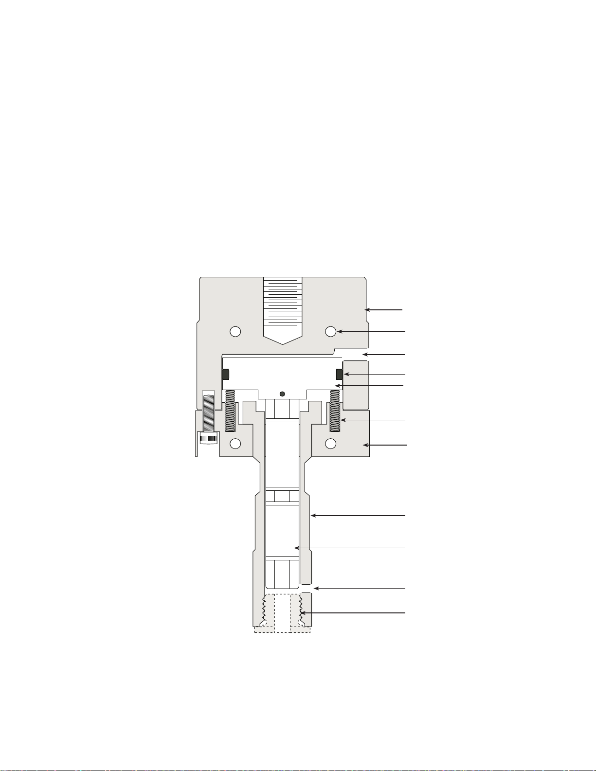
Model 680.01 High-Temperature Grips Functional Description
Base
Cooling water passages
Hydraulic Pressure Port
O-Ring
Piston
Spring, helical,
compression (6 ea.)
Grip Body
Grip Extension
Pushrod
Viewing Port
Specimen adapter
The pushrod, grip extension, and replaceable specimen adapters are made of
special alloy steel to withstand high furnace temperatures. The base and the grip
body are cooled by water flowing through internal passages.
The ends of correctly dimensioned button-end specimens are automatically
positioned with proper relationship to the pushrod by specimen adapters.
Viewing ports allow the end of a threaded specimen to be viewed for proper
insertion length into the specimen adapters.
A specimen with appropriate specimen adapters is installed in the grips.
Hydraulic fluid is applied to the pressure ports. The grip pistons move and push
their pushrods against the ends of the specimen. After testing, hydraulic pressure
is removed and the compression springs in each grip retract the pistons and
pushrods, releasing the specimen.
14
Component Identification
Model 680.01 High-Temperature Grips
Page 15

Model 680.01 High-Temperature Grip Accessories
E
Button-End Specimens
Threaded Specimens
max radius
The following accessories are available for the grips:
• Specimen adapters
• Attachment kits
• Cooling kits
• A hand-operated hydraulic pump.
Specimen adapters Specimen adapters are available in various sizes for both button-end and threaded
specimens. Specimen adapters are supplied in sets of two and are designed to be
used with specimens machined in either SI International or U.S. Customary
dimensions.
Specimen Dimensions (Grip-Ends Only)
For specimen dimensions which must be considered in order to meet an ASTM
(or any other) standard, refer to the appropriate standard. Special adapters, for
specimens not shown here, can be provided. Contact your local MTS sales
representative.
Button-End Dimensions
ART NUMBER ABC
P
041-901-901 0.85 in 0.53 in 0.5 in, +.000, -.001
041-901-902 0.85 in 0.53 in 0.25 in, +.000, -.001
041-901-907 21 mm 13 mm 12 mm, +.00, -.02
Threaded Dimensions
ART NUMBER DE
P
041-901-801
041-901-802 M12 x 1.75mm 28 mm
1/2
–13 UNC
1.1 in
Attachment kits Two attachment kits are needed to mount the grips in a load unit. One kit is
needed to mount a grip to the load unit’s force transducer; another kit is needed to
Model 680.01 High-Temperature Grips
15
Page 16

mount a grip to the actuator rod. Attachment kits are not supplied with a grip set,
Load cell
Load cell to grip
attachment kit
Upper Grip
Lower Grip
Actuator to grip
attachment kit
Actuator rod
1 Stud and
1 pair of
spiral
washers
and they must be ordered separately. Th e MTS base part number is 052-101-0xx.
Each kit contains a mounting stud, a set of spiral washers, and sometimes a shim
kit. Each kit is designed to mount the grip to a specific actuator or force
transducer.
16
Grip Attachment Components
Cooling kits Accessory kits for connecting a cooling water source and drain to the grips are
available in several configurations. A cooling kit is required for grip operation at
elevated temperatures. Each kit includes two water service manifolds (one to be
mounted to each load unit column), flow metering valve, polyethylene tubing,
and all required fittings.
Water Cooling Kits
IT PART NUMBER LOAD UNIT COLUMN
K
048-974-801 2.5–4.0 in diameter
048-974-802 2.5–4.0 in diameter
048-974-803 2.5–4.0 in diameter
048-974-804 6.0 in diameter
048-974-805 all
Model 680.01 High-Temperature Grips
Page 17

Hand-operated
Specimen Temperature
66.7 kN up to 700º C
(15 kip up to 1292º F)
8.9 kN at 1
000º C
(2 kip at 1832º F)
1
038º C
(1900º F)
482º C
(900º F)
0 kN
(0 kip)
66.7 kN
(15 kip)
Load
hydraulic pump
A hand-operated hydraulic pump kit (MTS part number 038-634-701) is a
required accessory for operating the grips. The kit includes the pump, with shutoff and release valves, a pressure gage, and hydraulic hoses for connecting the
pump to the grips. The kit also contains an extra supply of hydraulic fluid.
The pump is usually mounted to the base of the load unit (or near it). It includes
two hydraulic hoses; one is 1829 mm (72 in) long; and the other is 2286 mm (90
in.) long.
Model 680.01 High-Temperature Grips Specifications
The following are the specifications for the Model 680.01 high-temperature
Hydraulic Grips.
P
ARAMETER SPECIFICATION
Force rating See the following figure
Maximum specimen temperature 1000°C (1832°F)
Cooling water requirements
Temperature:
Flow
35°C (95°F) maximum
3.8 L/min (1 gpm) minimum,
at 0.276 MPa (40 psi)
Grip Load Rating as a Function of Temperature
Model 680.01 High-Temperature Grips
17
Page 18

Model 680.01 High-Temperature Grips Dimensions
B
C
D
F
A
E
Mounting holes in the base of each grip are threaded in either SI International
(millimeter) or U.S. Customary (inch) thread dimensions, as shown for
dimension “A” in the pervious table.
ARAMETER
P
A (mounting threads)
DIMENSION
M27 x 2mm (1 in
A
B 113 mm (4.44 in)
C 241 mm (9.48 in)
D 123 mm (4.96 in)
E (wrench flats) 29 mm (1.125 in)
F (travel) 10 mm (0.375 in)
G (specimen adapter wrench flats) 32 mm (1.25 in)
H (maximum diameter) 38 mm (1.5 in)
Weight (each grip) 9 kg (20 lb)
a SI International (U.S. Customary)
–14UNS)
18
Model 680.01 High-Temperature Grips
Page 19

Safety Information
Hazard Placard Placement
Hazard placards contain specific safety information and are affixed directly to the
system so they are plainly visible.
Each placard describes a system-related hazard. When possible, international
symbols (icons) are used to graphically indicate the type of hazard and the
placard label indicates its severity. In some instances, the placard may contain
text that describes the hazard, the potential result if the hazard is ignored, and
general instructions about how to avoid the hazard.
The following label is typically located on the grips.
ABEL DESCRIPTION
L
Grip Identification Placard.
Model
Assy. Rev
Cpty
MTS Systems Corporation
14000 Technology Drive
Eden Prairie, MN U.S.A. 55344-2290
See Manual
SN
PN 507258-01
Contains the following information:
• Model number
• Assembly number
• Revision
• SN
• Capacity
Model 680.01 High-Temperature Grips
19
Page 20

20
Model 680.01 High-Temperature Grips
Page 21

Installation
➊
➋
➌
Install the Grips
Install the HandOperated
Hydraulic Pump
Install the
Cooling Kit
Preload the Spiral
Washers
➍
This section describes how to install the Model 680.01 High Temperature Grips
into a load unit.
Contents Install the Grips 22
Install the Hand-Operated Hydraulic Pump 25
Install the Cooling Kit 26
Preload the Spiral Washers 27
Grip Water Cooling Assembly Configurations for Servohydraulic Frames
29
Typical installation The following diagram shows the main steps to install the grips. Usually the grips
are installed along with a furnace. In such cases, these instructions should be
used in conjunction with those provided for the furnace.
Typical Grip Installation
Model 680.01 High-Temperature Grips
21
Page 22

Install the Grips
Crosshead or
Force Transducer
Spiral
Washer
Set
Stud
Upper Grip
Lower Grip
Spiral
Washer
Set
Stud
Actuator Rod
Load Unit
Base Plate
An attachment kit is required for attaching each grip to the load unit. Kit
selection should be based on the mounting threads provided on the grips, which
must match corresponding threads on the device (force transducer or actuator
rod), to which the grip is to be attached. Refer to the information about the
attachment kits.
Grip Installation Components
Required equipment • An attachment kit for the actuator
• An attachment kit for the force transducer
• Molykote G•N paste lubricant (MTS part number 011-010-217 is a 2.8 oz.
tube; other sizes are available)
22
Model 680.01 High-Temperature Grips
Page 23

Preparation Ensure that the threads of all threaded components in the force train (between the
load cell and the actuator rod) are clean and in good condition.
As necessary, clean the connector studs and the internal threads of the force train
element(s) with a wire brush. Inspect all threads for signs of particle
contamination or corrosion. All damaged threads should be repaired or the
component should be replaced.
Installation procedure The following procedure assumes that the actuator is mounted in the base of the
load unit and the force transducer is mounted to the crosshead. If you have a load
unit with the actuator mounted to the crosshead, make the appropriate changes to
the following procedure.
1. Set up the load unit.
A. Turn on the system hydraulic pressure.
B. Adjust the actuator and crosshead position as necessary to allow
adequate room to install the grips.
C. Turn the hydraulic pressure off and ensure that system hydraulic
pressure has been reduced to zero before proceeding.
D. Lubricate all of the surfaces that will contact each other (screw threads,
spacers, and so forth) with Molykote G-n paste.
2. Mount the lower grip.
Mount the lower grip to the actuator piston rod. The attachment kit drawing
shows what components (such as shims, spiral washers, and so forth) should
be installed.
Note Insert a plug (with the same diameter as the stud) of compliant material,
such as cardboard or styrofoam, into the threaded mounting holes in
each grip, actuator, and force transducer. This will aid future grip
removal.
A. Thread the stud into the actuator. The connector stud should turn freely .
If any resistance is encountered, disassemble and correct the problem
before proceeding.
B. Add any required shims, spacers, or spiral washers to the stud. Ensure
that the spiral washers are set to their minimum thickness.
C. Position the lower grip to align it with the connecting stud and stabilize
the grip. Slowly screw the lower grip into the lower element of the
force train until it is snugged tight against the spiral washers. Ensure
that the spiral washers remain set to their minimum thickness.
3. Mount the upper grip.
Mount the upper grip to the force transducer on the crosshead. The
attachment kit drawing shows what components (such as shims, spiral
washers, and so forth) should be installed.
Note Ensure that the force transducer is properly aligned (see your load unit
A. Thread a stud into the upper grip.
Model 680.01 High-Temperature Grips
manual).
23
Page 24

B. With the connector stud is facing up, add any required shims, spacers,
or spiral washers to the stud. Ensure that the spiral washers are set to
their minimum thickness.
C. Reposition the grip as necessary for proper thread alignment. Slowly
screw the upper grip into the upper element of the force train until it is
snugged tight against the spiral washers. Ensure the spiral washers
remain set to their minimum thickness.
4. Align the grips.
Orientation is not critical. Just orient the grips so the hoses and water tubing
lines will provide the least interference with future work activities around
the load unit. You may also want to align the grips so that you can see the
view port which is helpful during specimen installation.
• It may be possible to rotate the actuator rod to achieve the desired
orientation. If the actuator rod cannot be rotated, remove the lower grip
and install shim washers between the spiral washers and the lower
element of the force train. Reinstall the grip (go to Step 2).
• It may be possible to rotate the force transducer when preloading the
spiral washers (see Step 5). If proper alignment of the force transducer
is not possible, remove the upper grip and install shim washers between
the spiral washers and the upper element of the force train. Reinstall the
grip (go to Step 3).
5. Tighten the grips.
See the appropriate procedure to preload the connector stud and return to
this procedure when done.
6. Connect the hydraulics.
The hydraulic source to operate the grips is from a hand-operated hydraulic
pump. Install the hand-operated hydraulic pump according to the
appropriate procedure, and return to this procedure when done.
Using the provided hydraulic hoses, make connections between the pressure
ports on each grip and the ports on the hand-operated hydraulic pump.
7. Install the cooling kit.
Install water hoses to the grips according to the appropriate procedure.
24
Model 680.01 High-Temperature Grips
Page 25

Install the Hand-Operated Hydraulic Pump
Reservoir Filler plug
Pressure Release
Output Pressure
Shut-off Va lve
When space permits, the hand-operated hydraulic pump can be mounted to the
sheet metal base of the load unit. If not, other mounting arrangements will need
to be devised. As a minimum, mount the pump on a board or on an adjacent
tabletop.
Note In order for the pump to operate, the reservoir end of the pump assembly
must be higher than the output end (or at least the same elevation).
1. Mount the pump. The preferred location is on the base of the load unit.
2. Connect hoses between the pump and the grips. Tighten both of the hoses at
the pump end. At the grip ends, leave the hoses connected, but loose
3. With the reservoir end of the pump pointed up, fill the reservoir with Quaker
Quintolubric hydraulic fluid, or equivalent. If the level is ever low, add more
hydraulic fluid.
4. With the hoses loose at the grip ends, close the pump’s pressure release
valve and actuate the pump until all air is expelled from the hoses, and then
tighten the hose fittings at the grips.
5. Apply 13.8 MPa (2000 psi) pressure to the grips and check for leaks at all
fittings.
6. After ensuring that all connections are leak free, open the pressure release
valve to release the pressure in the grips.
Model 680.01 High-Temperature Grips
25
Page 26

Install the Cooling Kit
Column Clamp
Water Manifold
The tubing loops
around the back of
the grips
Cool Supply
Hot Return
Hot Return
Cool Supply
Needle
Valve
Polyethylene Tubing
Compression Fitting
Compression Sleeve
Pipe Tube Adapter
Cooling kits circulate water through the grips to cool the them when they are
used in high-temperature situations. The water supply should go to the grip
component closest to the force transducer to help keep any heat transfer from the
force transducer.
1. Mount a water manifold on each load unit column.
2. Make up and install the tubing loops that are required (as shown in the
following figures). Make up the shorter loops first, then the longer ones.
3. Install the water supply and drain hoses.
26
Cooling Water Flow Schematic
Note Each grip uses a water manifold, one on each column. This keeps the
temperature of each column balanced.
Cooling Water Tubing Loop Assembly
Model 680.01 High-Temperature Grips
Page 27

Preload the Spiral Washers
WARNING
CAUTION
The components in the force train must be preloaded to prevent backlash during
operation. Preloading is done while a high tensile load is applied to a dummy
specimen mounted in the grips. While this load is applied, the spiral washers are
adjusted to remove any slack in the force train. When the applied load is
removed, the force train remain preloaded.
The load to be applied while preloading the studs should be at least 10% greater
than the maximum load that the force train will experience during actual testing.
Or, to preload the studs for grip operation at full rated load, the studs should be
preloaded to about 110% of the grips fatigue rating.
The procedure requires that the spiral washers be installed on each connector stud
in the force train. The spiral washers should be set to minimum thickness You
will also need two spanner wrenches.
1. Select force control.
2. Turn on the system hydraulic pressure.
3. Select a dummy specimen that will withstand a tensile force 10%– 20%
4. Install a dummy specimen in the grips according to the appropriate
greater than the maximum force to be applied during the test.
procedure.
The next step may apply a force greater than the force train capacity.
Exceeding the tensile load capacity of any element in the force train can
cause personal injury or equipment damage.
It is necessary to temporarily exceed the tensile load capacity to achieve the
requirements of Step 5 in this procedure. This is accomplished by increasing the
output pressure of the HPU.
5. Apply a static tensile force 10%– 20% higher than the maximum force to be
applied during testing.
If the spiral washers are not sufficiently tightened, the connector stud can
break when subjected to cyclic loads.
Improper preloading of the connector stud can cause eventual fatigue
resulting in connector stud breakage.
Sufficiently tighten the spiral washers as described in Step 6.
Model 680.01 High-Temperature Grips
27
Page 28

6. Using spanner wrenches, rotate the two halves of the spiral washers in
Connector Stud
Decrease Thickness
Medium Thickness
Do not exceed.
Connector
Stud
Increase Thickness
opposite directions to tighten them. The opening between the washers must
not exceed an arc of 30° from the closed position.
If more than a 30° arc is created, remove the tensile load from the specimen.
Remove the specimen and tighten the grips on the mounting studs, taking
care not to misalign the wedge openings. Repeat Step 4 through Step 6 of
this procedure.
7. Reduce tensile force to zero and remove the specimen.
8. Remove the system hydraulic pressure.
28
Connector Stud and Spiral Washers
Model 680.01 High-Temperature Grips
Page 29

Grip Water Cooling Assembly Configurations for Servohydraulic Frames
Hoses to
water
service
Cut hoses to required length at installation. MTS provides a hose (quantity 1)
with the water cooling assembly for conection to the water service. See the
following table for the hose length provided by MTS.
ART NUMBER COLUMN DIAMETER HOSE LENGTH FOR
P
ATER SERVICE
W
UPPLIED BY MTS
S
QUANTITY 1)
(
048-974-801 2.5–4 in (63.5–101.6 mm) none
048-974-802 2.5–4 in (63.5–101.6 mm) 12 ft (3.65 m)
048-974-803 2.5–4 in (63.5–101.6 mm) 24 ft (7.30 m)
048-974-804 6.0 in (152.4 mm) 12 ft (3.65 m)
048-974-805 All 12 ft (3.65 m)
048-974-801, 048-974-802, and 048-974-803
Model 680.01 High-Temperature Grips
29
Page 30

048-974-804
Hoses to
water
service
30
Model 680.01 High-Temperature Grips
Page 31

Hoses to
water
service
048-974-805
Model 680.01 High-Temperature Grips
31
Page 32

32
Model 680.01 High-Temperature Grips
Page 33

Operation
This section describes how to use the grips.
Contents Determine the Gripping Pressure 33
Install Threaded Specimens 35
Install Button-End Specimens 37
Adjust the Water Flow 38
Remove Specimens from the Grips 39
Determine the Gripping Pressure
The amount of hydraulic pressure to be applied to the grips must be sufficient to
prevent backlash between the specimen ends and the specimen adapters, and also
between the mating threads of the specimen adapters and the grip extensions,
during all parts of the loading cycle.
To also ensure that the grips will not be loaded beyond their force rating,
however, determining hydraulic pressure must start with temperature
considerations, rather than the forces to be applied to the specimen.
Note If the gripped ends of the specimen become deformed, reduce the
hydraulic gripping pressure. Re-compute the amount of pressure
required to grip the specimen.
Force versus
temperature
Determining the required hydraulic pressure is a two step process:
1. Determine that the maximum force (whether tensile or compressive) to be
applied to the specimen is within the grip rating, considering the
temperatures that the specimen will experience.
2. If anticipated forces are appropriate, use the “Required Pressure for the
Applied Force” graph to find the required gripping pressure.
The following figure shows that the grip force rating for specimen temperatures
up to 700°C is 67 kN (1292°F at 15,000 lb) is stable. The figure also shows that
the force rating is reduced proportionately for specimen temperatures between
700°C and 1000°C (1292°F and 1832°F), with a maximum force rating of 8.9 kN
at 1000°C (2000 lb at 1832°F).
Model 680.01 High-Temperature Grips
33
Page 34

Grip Force Rating versus Specimen Temperature
Specimen Temperature
66.7 kN up to 700º C
(15 kip up to 1292º F)
8.9 kN at 1
000º C
(2 kip at 1832º F)
1
038º C
(1900º F)
482º C
(900º F)
0 kN
(0 kip)
66.7 kN
(15 kip)
Load
Force versus hydraulic
pressure
The horizontal scale at the bottom of the graph shows required gripping pressure
versus maximum force to be applied, which is shown on the left hand vertical
scale.
The right hand vertical scale is provided as a convenience. Assuming that the
gage portion of the specimen has a diameter of 0.25 inches, the right hand scale
shows maximum engineering stress (for a 0.25 inch diameter specimen), versus
required gripping pressure on the bottom horizontal scale and also the equivalent
force on the left hand vertical scale.
34
Required Pressure for the Applied Force
Model 680.01 High-Temperature Grips
Page 35

Install Threaded Specimens
WARNING
Upper Grip Extension
Viewing Port
Specimen Adapter
Threaded Specimen
Perform the following procedure to mount threaded specimens in the grips.
Ensure that all grip parts are sufficiently cool before touching them.
Specimen mounting is a potentially hazardous procedure because hydraulic
pressure is applied to the system and actuator movement is required.
This can cause personal injury. It can also apply damaging forces to the
specimen, furnace, or to other fixtures.
Use extreme care while performing the following steps.
1. Determine the hydraulic pressure that must be applied to the grips in order
to adequately grip the specimen.
2. Ensure sure that the specimen adapters are clean and free of accumulated
oxide deposits.
3. Apply a liberal amount of anti-galling compound (supplied with the grips)
to the threads of both specimen adapters and to the threads of the specimen
to ensure easy removal after high-temperature operation.
4. Screw one end of the specimen into one of the specimen adapters until it
extends through the adapter.
Threaded Specimen Installation
5. Screw the specimen adapter fully into the grip extension of the upper grip.
6. While looking into the viewing port in the grip extension, screw the
specimen into the specimen adapter as required to center the end of the
specimen in the viewing port.
7. Screw the other specimen adapter fully into the extension of the lower grip.
Model 680.01 High-Temperature Grips
35
Page 36

Hydraulic power will be applied to the systems hydraulic actuator during the
WARNING
following steps.
This can cause personal injury and/or equipment damage.
Exercise caution to avoid having your hands pinched while working near the load
unit while hydraulic pressure is applied. If a high-temperature furnace is installed
in the load unit, exercise extreme care to prevent the actuator from applying any
force to the furnace; severe furnace damage will occur even if minimal force is
applied to the furnace.
8. Apply low hydraulic power to the system.
9. Select force control and adjust the actuator until the lower specimen adapter
just contacts the specimen.
Note When force control is selected to control the actuator and the force
command is set to zero, the actuator will automatically move the proper
amount when you screw the specimen into the specimen adapter.
10. While holding the specimen to prevent it from rotating, screw the specimen
into the lower specimen adapter by rotating the lower grip extension until
the specimen end is centered in the viewing port. (The extension rod has
flats for a 1-1/8” open end wrench.)
11. When satisfied that the specimen is properly installed (specimen adapters
fully screwed into grip extensions, specimen ends in centers of the viewing
ports), actuate the hand-operated pump until the required hydraulic pressure
is shown on the pressure gage.
36
Model 680.01 High-Temperature Grips
Page 37

Install Button-End Specimens
WARNING
Two Piece
Specimen Adapter
Upper Grip
Extension
Viewing Port
Specimen
Adapter
Button-end
Specimen
Perform the following procedure to mount button-end specimens in the grips.
Ensure that all grip parts are sufficiently cool before touching them.
• Specimen adapters for button-end specimens are two-piece adapters and
must be fully screwed into the grip extensions for operation.
• Specimens should have a button thickness no larger than 33 mm (0.540 in).
This will correctly position the specimen end for grip operation.
Specimen mounting is a potentially hazardous procedure because hydraulic
pressure is applied to the system and actuator movement is required.
This can cause personal injury. It can also apply damaging forces to the
specimen, furnace, or to other fixtures.
Use extreme care while performing the following steps.
1. Determine the hydraulic pressure that must be applied to the grips in order
to adequately grip the specimen.
2. Make sure that the specimen adapters are clean and free of accumulated
oxide deposits.
3. Apply a liberal amount of anti-galling compound (supplied with the grips)
to the threads of both specimen adapters to ensure easy removal after hightemperature operation.
4. Place the two halves of one specimen adapter around one end of the
specimen and screw the specimen adapter fully into the upper grip
extension.
Note Each grip specimen adapter for button-end specimens is made up of a
matched pair of halves. Each piece is marked with an alphabetic
identifier. Select a matched pair of pieces for each specimen adapter.
Model 680.01 High-Temperature Grips
37
Page 38

Hydraulic power will be applied to the systems hydraulic actuator during the
WARNING
following steps.
This can cause personal injury and/or equipment damage.
Exercise caution to avoid having your hands pinched while working near the load
unit while hydraulic pressure is applied. If a high-temperature furnace is installed
in the load unit, exercise extreme care to prevent the actuator from applying any
force to the furnace; severe furnace damage will occur even if minimal force is
applied to the furnace.
5. Apply low hydraulic power to the system.
6. Place the two halves of the other specimen adapter around the lower end of
the specimen and hold in place.
7. Select force control and adjust the actuator until the lower grip’s extension
just contacts the lower specimen adapter.
Note When force control is selected to control the actuator and the force
command is set to zero, the actuator will automatically move the proper
amount when you screw the specimen into the specimen adapter.
8. While holding the lower specimen adapter in place, screw it into the lower
grip extension until the adapter is fully threaded into the extension. This
may be done by rotating the specimen adapter or the extension. (The
extension has wrench flats for a 1-1/8 inch open-end wrench.)
Adjust the Water Flow
9. When satisfied that the specimen is properly installed (specimen adapters
fully screwed into grip extensions), actuate the hand-operated pump until
the required hydraulic pressure is shown on the pressure gage.
Water flow through the grips must be sufficient to prevent damage to the grips.
Minimum cooling water requirements are for 4 L/min (1 gpm) flow at 2.75 Pa
(40 psi). Fully open the water flow control valves. The temperature of the outer
surface of the grip body should not exceed 121°C (250°F) under any
circumstances.
38
Model 680.01 High-Temperature Grips
Page 39

Remove Specimens from the Grips
WARNING
CAUTION
Parts of the grips can be very hot after gripping specimens inside a hightemperature furnace.
This can produce very serious skin burns.
Do not touch the outer surfaces of the grips while hot. After completing a test,
leave cooling water running until the grips are safe to touch.
Be aware that the grip extension and specimen adapters will typically be much
hotter than the water-cooled grip body or grip base after gripping specimens at
elevated temperatures.
1. Turn the hydraulic hand pump pressure release valve counterclockwise until
the pressure indicated on the pressure gage reads zero. This allows the grip
pistons to retract, releasing the specimen.
2. After the grips are cool, use open-end wrenches to remove the specimen
adapters from the grip extensions.
If the specimen has not fractured during the test, turn on hydraulic power
and select force control of the actuator. This allows the actuator rod to
retract properly as a specimen adapter is removed.
3. Remove both the specimen adapters from the specimen ends. If the
specimen was a threaded specimen, it may be necessary to place the
specimen in a vise while removing the adapters.
Specimens can create debris that can settle in the grips.
Debris in the grips can cause damage to the grips.
Clean any debris out of the grips before installing a new specimen.
4. Clean the specimen adapters, according to the appropriate procedure.
Model 680.01 High-Temperature Grips
39
Page 40

40
Model 680.01 High-Temperature Grips
Page 41

Maintenance
CAUTION
WARNING
Contents Clean the Grips 41
Clean the Grips
The Model 680.01 High-Temperature Grips are designed to be used in high
temperature environments. After every use in a high temperature environment,
the specimen, the adapters, and grip extensions should be cleaned and lubricated.
Add Hydraulic Fluid to the Hand Pump 42
Specimen adapters and the threaded ends of the grip extension rods should be
cleaned and lubricated after each use. Because they must be removed from the
grip before another specimen may be tested, the small amount of additional time
involved in wiping and re-lubricating the threads is worth while, especially when
the grips are repeatedly exposed to high-temperatures.
If grip cleaning procedures are not performed as recommended, the grips
may not operate properly.
When used repeatedly in high-temperature environments, grip parts can become
welded together if they are not properly maintained.
1. Loosen and remove all anti-galling compound from the threads of the
specimen adapters and also from the threads of the grip extensions. Use a
wire brush if necessary.
Many chemicals used for cleaning or as solvents, such as isopropyl alcohol,
are flammable and can be ignited by nearby objects at high-temperature.
This can cause burn injuries or cause larger fires that are dangerous to life
and property.
Make sure that the grips and nearby furnaces are cool before using any
flammable substances. Isopropyl alcohol may be used to loosen deposits that are
difficult to remove by wire brush alone.
2. If compressed air is available, blow any remaining debris from inside the
ends of the grip extensions.
3. Before re-installing the specimen adapters, apply anti-seize lubricant to the
threads of the adapters and grip extensions.
Model 680.01 High-Temperature Grips
41
Page 42

Add Hydraulic Fluid to the Hand Pump
Output Pressure
Shut-off Valve
Pressure Release
Reservoir Filler Plug
Check the fluid level in the reservoir of the hand pump occasionally by removing
the pump’s reservoir plug and observing the level shown on the dip stick. If the
level is low, add Quaker Quintolubric hydraulic fluid, or equivalent, only.
Difficulty in obtaining or maintaining the pressure required for grip operation
may be caused by low fluid level.
42
Model 680.01 High-Temperature Grips
Page 43

Page 44

m
MTS Systems Corporation
14000 Technology Drive
Eden Prairie, Minnesota 55344-2290 USA
Toll Free Phone: 800-328-2255
(within the U.S. or Canada)
Phone: 952-937-4000
(outside the U.S. or Canada)
Fax: 952-937-4515
E-mail: info@mts.com
Internet: www.mts.com
ISO 9001:2000 Certified QMS
 Loading...