

Page 1

be certain.
m
Series 653 High-Temperature Furnaces
Product Information
015-059-101 J
Page 2

Copyright information © 1997–1999, 2004, 2008, 2013 MTS Systems Corporation. All rights reserved.
Trademark information MTS is a registered trademark of MTS Systems Corporation within the United
States. This trademark may be protected in other countries.
Rath Inc. is a registered trademark of Rath, Inc.
Publication information
Manual Part Number Publication Date
015-059-101 A June 1997
015-059-101 B July 1997
015-059-101 C January 1998
015-059-101 D November 1999
015-059-101 E June 2004
015-059-101 F September 2004
015-059-101 G March 2008
015-059-101 H August 2012
015-059-101 J February 2013
015-059-101 J June 2014
(reissue)
2
Manual Template 4.3
Page 3

Contents
EC Declaration of Conformity 5
Technical Support 7
How to Get Technical Support 7
Before You Cont act MTS 7
If You Contact MTS by Phone 8
Problem Submittal Form in MTS Manuals 9
Preface 11
Before You Begin 11
Conventions 12
Documentation Conventions 12
Introduction 15
653 High-Temperature Furnace Physical Description 15
653 High-Temperature Furnace Functional Description 17
Series 653 High-Temperature Furnace Construction 18
Series 653 High-Temperature Furnace Specifications 19
Safety Information Hazard Placard Placement 21
Installation 23
About Series 653 High-Temperature Furnace Installation 23
Mounting the 653 Furnace to the Load Unit 25
Series 653 High-Temperature Furnace Cable Connections 27
Filing Insulation Inserts 28
About the Extensometer 29
Series 653 High-Temperature Furnace Contents
3
Page 4

Operation 31
Preparing to Run a Test 32
Achieving a Low-Temperature Gradient 33
Maintenance 35
Cleaning the Series 653 High-Temperature Furnace 35
4
Contents
Series 653 High-Temperature Furnace
Page 5
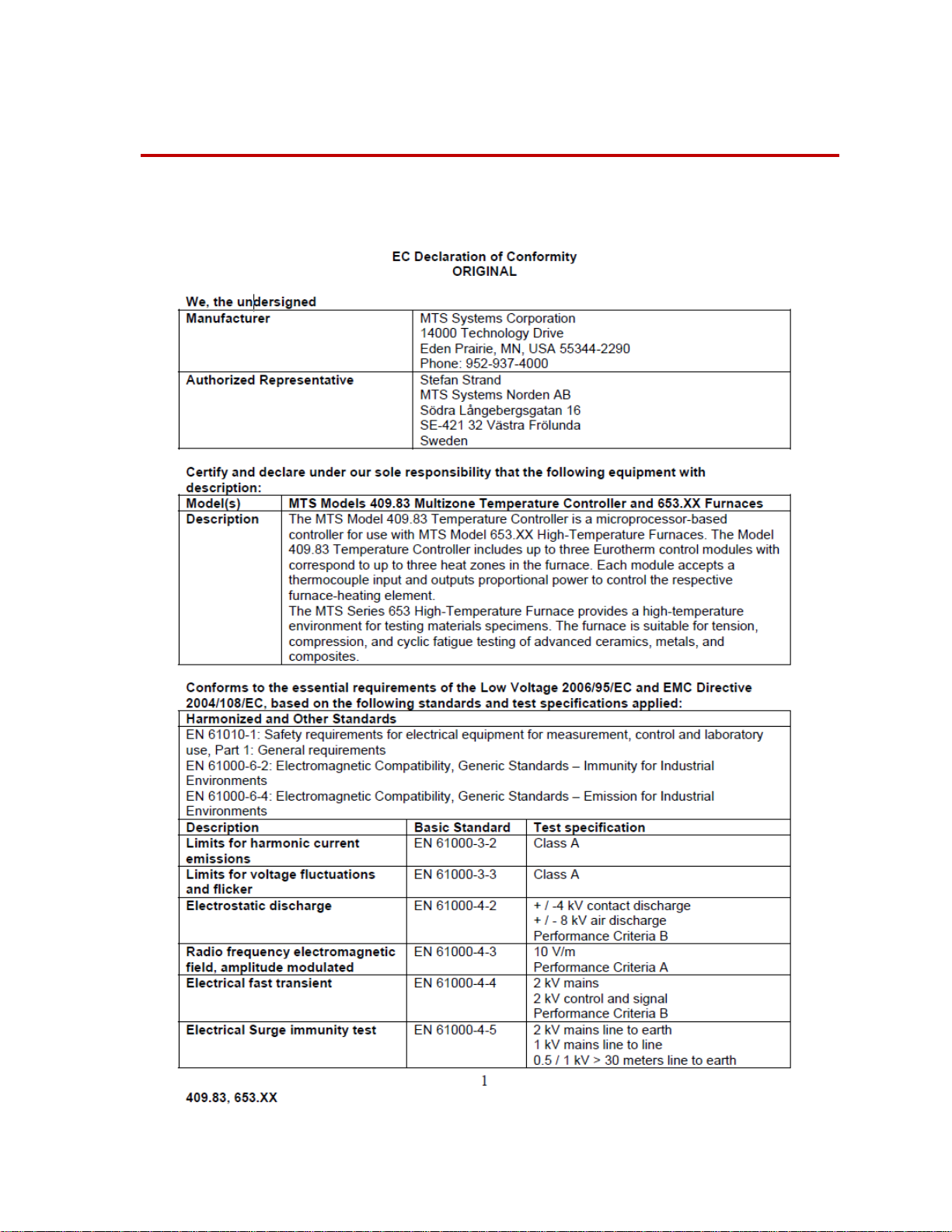
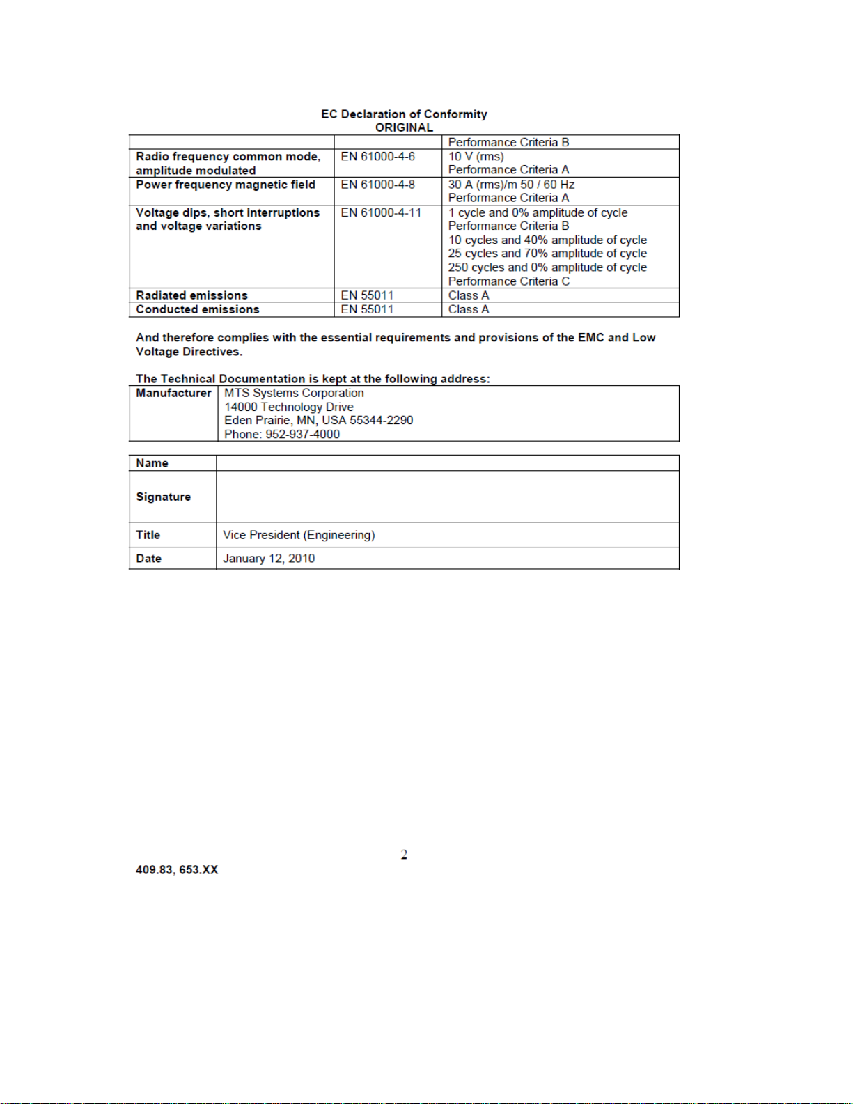
EC Declaration of Conformity
Series 653 High-Te mperature Furnace EC Declaration of Conformity
5
Page 6
EC Declaration of Conformity
6
Series 653 High-Temperature F urnace
Page 7

Technical Support
How to Get Technical Support
How to Get Technical Support
Start with your
manuals
Technical support
methods
MTS web site
www.mts.com
E-mail techsupport@mts.com
Telephone MTS Call Center 800-328-2255
Fax 952-937-4515
The manuals supplied by MTS provide most of the information you need to use
and maintain your equipment. If your equipment includes MTS software, look
for online help and README files that contain additional product inform ation.
If you cannot find answers to your technical questions from these sources, you
can use the internet, e-mail, telephone, or fax to contact MTS for assistance.
MTS provides a full range of support services after your system is installed. If
you have any questions about a system or product, contact MTS in one of the
following ways.
The MTS web site gives you access to our technical support staff by means of a
Technical Support link:
www.mts.com > Contact Us > Service & Technical Support
Weekdays 7:00 A.M. to 5:00 P.M., Central Time
Please include “Technical Support” in the subject line.
Before You Contact MTS
MTS can help you more efficiently if you have the following information
available when you contact us for support.
Know your site
number and system
number
Series 653 High-Temperature Furnace Technical Support
The site number contains your company number and identifies your equipment
type (material testing, simulation, and so forth). The number is usually written on
a label on your MTS equipment before the system leaves MTS. If you do not
have or do not know your MTS site number, contact your MTS sales engineer.
Example site number: 571167
When you have more than one MTS system, the system job number identifies
which system you are calling about. You can find your job number in the papers
sent to you when you ordered your system.
Example system number: US1.42460
7
Page 8

If You Contact MTS by Phone
Know information from
prior technical
If you have contacted MTS about this problem before, we can recall your file.
You will need to tell us the:
assistance
• MTS notification number
• Name of the person who helped you
Identify the problem Describe the problem you are experiencing and know the answers to the
following questions:
• How long and how often has the problem been occurring?
• Can you reproduce the problem?
• Were any hardware or software changes made to the system before the
problem started?
• What are the model numbers of the suspect equipment?
• What model controller are you using (if applicable)?
• What test configuration are you using?
Know relevant
computer information
If you are experiencing a computer problem, have the following information
available:
• Manufacturer’s name and model number
• Operating software type and service patch information
• Amount of system memory
• Amount of free space on the hard drive in which the application resides
• Current status of hard-drive fragmentation
• Connection status to a corporate network
Know relevant
For software application problems, have the following information available:
software information
• The software application’s name, version number, build number, and if
available, software patch number. This information is displayed briefly
when you launch the application, and can typically be found in the “About”
selection in the “Help” menu.
• It is also helpful if the names of other non-MTS applications that are
running on your computer, such as anti-virus software, screen savers,
keyboard enhancers, print spoolers, and so forth are known and available.
If You Contact MTS by Phone
Your call will be registered by a Call Center agent if you are calling within the
United States or Canada. Before connecting you with a technical support
specialist, the agent will ask you for your site number, name, company , company
address, and the phone number where you can normally be reached.
Technical Support
8
Series 653 High-Temperature Furnace
Page 9

Problem Submittal Form in MTS Manuals
If you are calling about an issue that has already been assigned a notification
number, please provide that number. You will be assigned a unique notification
number about any new issue.
Identify system type To assist the Call Center agent with connecting you to the most qualified
technical support specialist available, identify your system as one of the
following types:
• Electromechanical materials test system
• Hydromechanical materials test system
• Vehicle test system
• Vehicle component test system
• Aero test system
Be prepared to
Prepare yourself for troubleshooting while on the phone:
troubleshoot
• Call from a telephone when you are close to the system so that you can try
implementing suggestions made over the phone.
• Have the original operating and application software media available.
• If you are not familiar with all aspects of the equipment operation, have an
experienced user nearby to assist you.
Write down relevant
Prepare yourself in case we need to call you back:
information
• Remember to ask for the notification number.
• Record the name of the person who helped you.
• Write down any specific instructions to be followed, such as data recording
or performance monitoring.
After you call MTS logs and tracks all calls to ensure that you receive assistance and that action
is taken regarding your problem or request. If you have questions about the status
of your problem or have additional information to report, please contact MTS
again and provide your original notification number.
Problem Submittal Form in MTS Manuals
Use the Problem Submittal Form to communicate problems you are experiencing
with your MTS software, hardware, manuals, or service which have not been
resolved to your satisfaction through the technical support process. This form
includes check boxes that allow you to indicate the urgency of your problem and
your expectation of an acceptable response time. We guarantee a timely
response—your feedback is important to us.
The Problem Submittal Form can be accessed:
• In the back of many MTS manuals (postage paid form to be mailed to MTS)
• www.mts.com > Contact Us > Problem Submittal Form (electronic form to
be e-mailed to MTS)
Series 653 High-Temperature Furnace Technical Support
9
Page 10

Problem Submittal Form in MTS Manuals
Technical Support
10
Series 653 High-Temperature Furnace
Page 11

Before You Begin
Preface
Before You Begin
Safety first! Before you attempt to use your MTS product or system, read and understand the
Safety manual and any other safety information provided with your system.
Improper installation, operation, or maintenance of MTS equipment in your test
facility can result in hazardous conditions that can cause severe personal injury or
death and damage to your equipment and specimen. Again, read and understand
the safety information provided with your system before you continue. It is very
important that you remain aware of hazards that apply to your system.
Other MTS manuals In addition to this manual, you may receive additional MTS manuals in paper or
electronic form.
If you have purchased a test system, it may include an MTS System
Documentation CD. This CD contains an electronic copy of the MTS manuals
that pertain to your test system, including hydraulic and mechanical component
manuals, assembly drawings and parts lists, and op eration and preventive
maintenance manuals. Controller and application software manuals are typically
included on the software CD distribution disc(s).
Series 653 High-Temperature Furnace Preface
11
Page 12

Conventions
DANGER
WARNING
CAUTION
Conventions
Documentation Conventions
The following paragraphs describe some of the conventions that are used in your
MTS manuals.
Hazard conventions As necessary, hazard notices may be embedded in this manual. These notices
contain safety information that is specific to the task to be performed. Hazard
notices immediately precede the step or procedure that may lead to an associated
hazard. Read all hazard notices carefully and follow the directions that are given.
Three different levels of hazard notices may appear in your manuals. Following
are examples of all three levels.
Note For general safety information, see the safety information provided with
your system.
Danger notices indicate the presence of a hazard with a high level of risk which,
if ignored, will result in death, severe personal injury, or substantial property
damage.
Warning notices indicate the presence of a hazard with a medium level of risk
which, if ignored, can result in death, severe personal injury, or substantial
property damage.
Caution notices indicate the presence of a hazard with a low level of risk which,
if ignored, could cause moderate or minor personal injury, equipment damage, or
endanger test integrity.
Notes Notes provide additional information about operating your system or highlight
easily overlooked items. For example:
Note Resources that are put back on the hardware lists show up at the end of
the list.
Special terms The first occurrence of special terms is shown in italics.
Illustrations Illustrations appear in this manual to clarify text. It is important for you to be
Electronic manual
conventions
Preface
12
aware that these illustrations are examples only and do not necessarily represent
your actual system configuration, test application, or software.
This manual is available as an electronic document in the Portable Document
File (PDF) format. It can be viewed on any computer that has Adobe Acrobat
Reader installed.
Series 653 High-Temperature Furnace
Page 13

Documentation Conventions
Hypertext links The electronic document has many hypertext links displayed in a blue font. All
blue words in the body text, along with all contents entries and index page
numbers, are hypertext links. When you click a hypertext link, the application
jumps to the corresponding topic.
Series 653 High-Temperature Furnace Preface
13
Page 14

Documentation Conventions
14
Preface
Series 653 High-Temperature Furnace
Page 15

653 High-Temper ature Furnace Physical Description
Introduction
The MTS Series 653 High-Temperature Furnace provides a high-temperature
environment for testing material specimens. The furnace is suitable for tension,
compression, and cyclic fatigue testing of advanced ceramics, metals, and
composites. It is usually installed in an MTS load unit and is used with MTS
temperature controllers. The Series 653 Furnace accommodates MTS Model
632.59, 632.53, 632.50, 632.51, and 632.54 Extensometers and various MTS
specimen grips.
653 High-Temperature Furnace Physical Description
The Series 653 Furnace has a hot zone produced by two, four, or six horizontallyoriented silicon carbide heating elements. An insulation plate separates the
elements to provide reliable zone separation. On standard models, the heating
elements are controlled as a single, double, or triple hot zone. Each furnace
comes with a K (Type “R” optional) thermocouple, MTS digital PID temperature
control system, and mounting bracket.
All furnace insulation is made of polycrystalline alumina fiber material. For the
653.01 & 653.02, you must file a hole in the insulation inserts to accommodate a
specific specimen cross section. The 653.03 comes with insulation inserts that are
precut for MTS hot grip extensions, and uncut inserts. The 653.04 furnace comes
with precut insulation for MTS hot grip extensions. You can order and modify
additional inserts to suit a variety of test needs.
MTS furnace mounting accessories combine with the center-split furnace design
to provide convenient installation and removal of test specimens and insulation
inserts. Adjustable pivot mounts built into the mounting bracket allow for smooth
Series 653 High-Temperature Furnace Introduction
15
Page 16

653 High-Temperature Furnace Physical Description
furnace opening and easy operation. Latches built into the front of the furnace
ensure tight furnace sealing.
16
Introduction
Series 653 High-Temperature Furnace
Page 17

653 High-Temperature Furnace Functional Description
High
Temperature
Furnace
Upper Control
Signal
Lower Control
Signal
Lower Thermocouple Signal
Upper Thermocouple Signal
element
element
Temperature
Controller
653 High-Temperature Furnace Functional Description
Temperature control
system
The Series 653 High-Temperature Furnace is monitored and controlled by the
Model 409.83 Temperature Controller. The temperature controller contains a
control module for each hot zone in the furnace. Each control module accepts a
thermocouple input and outputs proportional power to the respective furnace
heating element. With certain controller cables, power to the elements is shut off
when there is a controller interlock.
Series 653 High-Temperature Furnace Introduction
Temperature Controller/Furnace Block Diagram
(Two-Zone Model Shown)
17
Page 18

Series 653 High-Temperature Furnace Construction
Series 653 High-Temperature Furnace Construction
The furnace uses a center-split design which provides easy specimen and fixture
access. Ports allow thermocouples and an extensometer to extend into the hot
zone.
Heating elements The silicon carbide heating elements provide rapid heating, low heat loss, and
long life.
Insulation The insulation material is made of polycrystalline alumina fiber and is capable of
long-term operation at the maximum operating range of the furnace.
Furnace Heating Elements and Insulation Inserts
(Model 653.02 shown)
18
Introduction
Series 653 High-Temperature Furnace
Page 19

Series 653 High-Temperature Furnace Specifications
Series 653 High-Temperature Furnace Specifications
a
B
653.04
†
Temperature
Max/Min
d
High-Temperature Furnace Specificat ions
653.01 653.02
1400°C/100 °C 1400°C/100 °C 1400°C/100 °C 1400°C/100°C
653.03
Overall Height 55 mm 86 mm 126 mm 220 mm
Hot Zone
19 mm 50 mm 90 mm 185 mm
Height
Hot Zone
50 mm 50 mm 62.5 mm 62.5 mm
Width and
Depth
Number of
12 23
Zones
Heater Element
Power
Control Point
Stability
d
Heating Ramp
100/120 V or
220/240 V
50/60 Hz
±1°C from 100 °C
to 1400 °C
d
100°C/min 100°C/min 100°C/min 100°C/min
100/120 V or
220/240 V
50/60 Hz
±1°C from 100 °C to
1400 °C
100/120 V or
220/240 V
50/60 Hz
±1°C from 100 °C
to 1400 °C
220/240 V
50/60 Hz
±1°C from 100
°C to 1400 °C
C
Minimum Time
15 min 15 min 15 min 15 min
to Reach
Maximum
Temperature
d
a Specifications are subject to change without notice. Contact MTS for verification of
specifications critical to your needs.
b This furnace is particularly well-suited for use when a lower thermal gradient is desired on a
tensile or fatigue specimen.
c Designed to accommodate high-temperature bend testing of ceramic materials per ASTM
C1211 or JIS R1604.
d Unloaded, sealed furnace. Furnace performance is dependent on a number of factors including
test type, specimen type, grip configuration, and furnace size. Adding a specimen or grips to the
furnace will reduce4 the maximum achievable temperature and increase the time to reach
temperature. Typical performance of a 653.04 Furnace with MTS 680 grips is 1050 °C maximum
temperature in approximately 1 hour and 15 minutes. A low heat load specimen such as a thin
wire (with grips outside the furnace) will be able to reach a higher temperature in a shorter period
of time.
Series 653 High-Temperature Furnace Introduction
19
Page 20

Series 653 High-Temperature Furnace Specifications
20
Introduction
Series 653 High-Temperature Furnace
Page 21

Safety Information Hazard Placard
High Temperature Furnace
MTS Systems Corporation Eden Prairie, MN U.S.A. 55344-2247
Assy. No.
PN 525462-01
Model No.
Rev.
Serial No.
Placement
Hazard placards contain specific safety information and are affixed directly to the
system so they are plainly visible.
Each placard describes a system-related hazard. When possible, international
symbols (icons) are used to graphically indicate the type of hazard and the
placard label indicates its severity. In some instances, the placard may contain
text that describes the hazard, the potential result if the hazard is ignored, and
general instructions about how to avoid the hazard.
The following labels are typically located on the furnace.
ABEL DESCRIPTION
L
High Temperature Furnace ID label.
Lists the following:
• Model number
• Serial number
• Assembly number
• Revision
Series 653 High-Te mperature Furnace Safety Information Hazard Placard Placement
21
Page 22

ABEL DESCRIPTION
L
WARNING
Hot surface.
Can burn skin.
WARNING
Hazardous voltage.
Can cause severe injury or death.
Turn off power before servicing.
Safety Information Hazard Placard Placement
22
Series 653 High-Temperature Furnace
Page 23

About Series 653 High-Temperature Furn ace
Installation
The Series 653 High-Temperature Furnace is usually supplied as part of a
complete testing system, and the installation procedures are performed by MTS
personnel. However, furnaces purchased as replacement or add-on items require
installation as described in this section.
Items required The following items are required to install a Series 653 High-Temperature
Furnace in an MTS load unit:
• The basic furnace and bracket assembly
• A socket wrench (socket size depends on bracket installed)
• A round or flat file for shaping the insulation inserts to fit the test specimen
if using 653.01, .02, or .03 (one spare s et of insu latio n ins erts is su ppli ed wit h
the furnace.)
Pre-installation tasks The following tasks should be completed prior to installing or replacing the
furnace:
1. Install the load train components (load cell, grips, and so forth) that will be
used during the testing.
2. Install a specimen in the grips using appropriate procedures.
3. Adjust the vertical position of the load unit crosshead, if necessary, so that,
with the specimen in the grips, the actuator is at the desired position for
testing.
Installation overview The following is an overview of furnace installation tasks:
1. Mount the furnace on the load unit columns.
2. Connect all electrical cables and jumpers.
3. File, drill, or cut holes in the insulation inserts to suit the test specimen.
4. Install the extensometer.
Use Available installation videos for detailed instructions.
The extensometer, if used, is mounted independently and its extension rods
extend into the furnace through an opening in the front of the furnace.
About Series 653 High-Temperature Furnace Installation
This procedure requires that a specimen be installed in the load unit to act as a
reference point for furnace installation. If the upper and lower insulation inserts
have not yet been notched to accommodate the specimen, perform the
appropriate procedure before proceeding here. The specimen and inserts used
during installation should resemble those used during actual testing.
The furnace is attached by means of a mounting bracket to two columns of the
load unit.
Series 653 High-Temperature Furnace Installation
23
Page 24

About Series 653 High-Temperature Furnace
WARNING
Mounting
considerations
Consider the following when mounting the furnace in the load unit:
• Proper vertical position of the furnace depends on the dimensions of load
unit components (such as the load cell, grips, cooling adapters, extension
rods, and so forth) and the specimen to be tested.
• The furnace should be positioned so that the axis of the specimen is centered
in the hot zone of the furnace.
• When properly positioned in the vertical plane, the middle of the specimen
length will be in the vertical center of the hot zone and the actuator will be at
the desired position for testing.
• When properly positioned in the horizontal plane, the specimen will be
centered on the holes you have cut in the insulation inserts when the furnace
is closed for operation.
• The furnace must be mounted such that the lamps on the controller are
visible from the furnace.
Materials heated in the furnace are hot and can ignite flammable materials.
Materials on fire can cause serious injury to per sonnel, damage to
equipment, or both.
Do not operate the furnace near flammable materials. Allow sufficient time for the
test materials to cool before handling them.
24
Installation
Series 653 High-Temperature Furnace
Page 25

Mounting the 653 Furnace to the Load Unit
CAUTION
Furnace
Halves
Clamp
Support Bar
Temperature Controller
1. Assemble the bracket assembly to the rear of the furnace.
The furnace insulation inserts are fragile.
Improper installation can damage furnace installation inserts.
Exercise caution to avoid damaging the insulation inserts during installation.
2. Open the furnace and support it in the approximate proper position while
fastening the support bar and clamp to the load unit column.
3. Make sure that all of the socket head cap screws are sufficiently tightened to
support the furnace.
Mounting the 653 Furnace to the Load Unit
Load Unit Installation Using Bracket Assemb ly
Series 653 High-Temperature Furnace Installation
25
Page 26

Mounting the 653 Furnace to the Load Unit
Furnace Assembly Front View
26
Installation
Series 653 High-Temperature Furnace
Page 27

Series 653 High-Temperature Furnace Cable
WARNING
Input Power Socket
Furnace
(Rear View)
Furnace
Output
Thermocouple
Assemblies
Feedthrough
Series 653 High-Temperature Furnace Cable Connections
The thermocouple cables must be connected between the Series 653 HighTemperature Furnace and the temperature controller.
Procedure 1. Connect the furnace thermocouple output cables (MTS cable 525655-xx).
Temperature measurements are provided through a Type K (Type “R”
optional) thermocouple lead for each zone. The thermocouple assembly
should be connected to the rear furnace panel. The other end should be
plugged into the outlet labeled “J1” or “J2” on the temperature controller
bottom panel.
The furnace/controller must be connected to a supply source which
incorporates a residual current operated circuit-breaker which interrupts the
supply at a differential current of 30 mA or less.
Due to the fact that the heaters are hazardous live and are accessible, the
equipment must be connected to a supply source that incorporates such a circuit
breaker.
2. Connect the furnace power input cables (MTS cable 518818-xx).
Socket style connectors “J4” and “J5” transfer the heater control signal (line
voltage) from the temperature controller to the furnace heater elements.
Furnace Connections (Model 653.02 shown)
Series 653 High-Temperature Furnace Installation
27
Page 28

Filing Insulation Inserts
WARNING
Filing Insulation Inserts
The Series 653 High-Temperature Furnace includes one set of insulation inserts
installed in the unit, and one spare set. Before testing, you must file (or cut) holes
for the specimen in the inserts. If specimens of various sizes are to be tested, you
will need inserts accommodating each different size.
Abrasion of insulation inserts produces airborne dust. This product
contains a substance which has been identified by the International Agency
for Research on Cancer (IARC) as possible carcinogenic to humans.
Airborne dust from the insulation may cause temporary irritation to the
eyes, skin, and respiratory tract, and possibly cause a cancer hazard by
inhalation.
Take precautionary measures by minimizing airborne fibers with engineering
controls. Wear a NIOSH/MSHA approved respirator. Wear long sleeved loose
fitting clothing, eye protection and gloves. Wash work clothing separately and
rinse washing machine after use.
The insulating component material is listed below. It is important to minimize
exposure to the dust from this material.
ANUFACTURER INSULATION TRADE NAME APPLICABLE MSDS
M
Rath Inc. KVS 164/302 Rath-NRK-MSDS
Procedure To remove the inserts:
1. Pivot the furnace halves fully open to expose the inserts.
2. Grasp and pull the inserts from the furnace.
To shape the inserts for the test specimen:
1. Use a round or flat file to make a hole in the insulation inserts that closely
match the specimen geometry.
To reinstall or replace the inserts:
1. Push the inserts back into their sockets.
022
Available from MTS
28
Installation
Series 653 High-Temperature Furnace
Page 29

About the Extensometer
About the Extensometer
The extensometer, if used, is mounted independently. Its extension rods extend
into the furnace through an opening filed in the front of the furnace. Refer to the
product manual (or installation drawing, if provided) that accompanied the
extensometer for installation information.
Series 653 High-Temperature Furnace Installation
29
Page 30

About the Extensometer
30
Installation
Series 653 High-Temperature Furnace
Page 31

Operation
CAUTION
WARNING
Prior to performing a materials test at high temperatures, familiarize yourself
with the operation of the other components that make up the complete testing
system.
Adapting furnace
insulation
Before using the 653.01 or 653.02 furnace, you must file holes in the upper and
lower layers of insulation to accommodate the ends of the specimen. These ends
extend outward from the furnace toward the grips. Filing the insulation produces
dust. Be sure to use proper filing methods when working with or handling
furnace insulation.
Proper furnace use • To reduce the possibility of damage to or destruction of the furnace, make
sure that the hydraulic control electronics are set for appropriate
displacement limits.
• When maximum operating temperatures are to be used, note the maximum
recommended heating ramp is 100°C (212°F) per minute.
• The heater elements are designed to operate at temperatures between 100°C
(212°F) and 1400°C (2552°F). Using the furnace above 1400°C can
significantly shorten the life of the heating elements and insulation.
Improper use can shorten the life of heater elements and insulation
components.
Do not open the high-temperature furnace while it is hot or operating. Allow
sufficient time for the furnace to cool before opening the furnace. Rapid
cooling reduces heating element life.
Avoid contacting the heating elements when installing a test specimen or test
fixtures. The heating elements are easily broken.
Avoid contaminating the heating elements with foreign substances which can
reduce service life. Wear gloves if it is necessary to handle heating elements.
Explosions in the furnace can cause death or serious in jury.
Do not use this furnace to heat materials that pose hazards of explosion,
implosion, or the release of toxic or flammable gases
Series 653 High-Temperature Furnace Operation
31
Page 32

Preparing to Run a Test
WARNING
WARNING
Preparing to Run a Test
Materials heated in the furnace are hot and can ignite flammable materials
or cause serious burns.
Do not operate the furnace near or above flammable materials. Allow sufficient
time for the test materials to cool before handling them.
The protection provided by this equipme nt can be impaired if this furnace is
not used in its intended manner.
Do not operate the furnace in a manner contrary to its intended use.
Detailed instructions for operating and adjusting all of the devices involved can
be found in the applicable manuals.
Before proceeding, make sure that the furnace is installed properly.
Procedure 1. Open the furnace.
2. Install the insulation inserts.
If the insulation inserts are not suitable for the cross section of the
specimens to be tested, install new insulation inserts.
3. Install the test specimen.
Refer to the grip or grip power supply manual for the proper installation
procedure.
4. Install the extensometer.
No direct mechanical connection between the furnace and the extensometer
is required. The extensometer is supported by independent means and its
extension rods enter the furnace through holes in the furnace in order to
contact the specimen. Refer to the extensometer manual or installation
drawing, if provided, for the proper installation procedures.
5. Close the furnace.
Fasten the latches on the front of the furnace.
6. Adjust the extensometer cooling water supply for the required flow rate, if
equipped.
32
Operation
7. Run a test.
Refer to the temperature controller manual for information on running a test.
Series 653 High-Temperature Furnace
Page 33

Achieving a Low-Temperature Gradient
Several factors affect the specimen thermal gradient. To establish and ensure
temperature uniformity, some experimentation should be done prior to
performing a test.
The following factors should be considered:
• Position of the heater element.
• T o minimize chimney effect, make sure that the insulation inserts closely fit
the specimen geometry.
• Reduce excessive water flow through the extensometer heat shield and through
the extensometer and grips. However, do not reduce the water flow below the
requirements of each water cooled device. Each water cooled device that may
be used with the furnace has minimum requirements for flow, pressure, and/or
constant cooling water temperature. Refer to the specifications for each water
cooled device. The grip water cooling manifold has flow switches that will
shut off the furnace if cooling water drops below a safe level.
• The furnace should be situated in a controlled environment which is free of
drafts and temperature changes.
Achieving a Low-Temperature Gradient
• The position of the feedback thermocouple affects how close the furnace
tracks the programmed temperature setting. Positioning the thermocouple
on the specimen provides the most accurate specimen temperature reading.
• The temperature reading near the heating element may not be the same as
the temperature reading near the specimen. This is due to the thermal losses
caused by the process of radiating heat between the heating elements and the
specimen.
• Deteriorated thermocouples can produce inaccurate readings.
Series 653 High-Temperature Furnace Operation
33
Page 34

Achieving a Low-Temperature Gradient
34
Operation
Series 653 High-Temperature Furnace
Page 35

Cleaning the Series 653 High-Temperature Furnace
WARNING
WARNING
Maintenance
This section provides information regarding service of the high-temperature
furnace.
The surface of the furnace can become extremely hot.
Touching the furnace before it has cooled can severely burn skin.
Allow sufficient time for the furnace to cool off before servicing the furnace.
Cleaning the Series 653 High-Temperature Furnace
The surface of the furnace can become extremely hot.
Touching the furnace before it has cooled can severly burn skin.
Allow sufficient time for the furnace to cool off before servicing the furnace.
Keep the exterior of the Model 653 High-Temperature Furnace free from dust
and other debris. Should the furnace require cleaning, keep the following points
in mind:
• Power should be disconnected from the furnace before cleaning.
• Use a soft cloth to remove dust and other debris from the exterior of the
furnace. If a cleaning agent is required, use only a mild detergent and water.
• Allow for sufficient dry time before reconnecting power to the furnace.
Series 653 High-Temperature Furnace Maintenance
35
Page 36

Cleaning the Series 653 High-Temperature Furnace
36
Maintenance
Series 653 High-Temperature Furnace
Page 37

Page 38

m
MTS Systems Corporation
14000 Technology Drive
Eden Prairie, Minnesota 55344-2290 USA
Toll Free Phone: 800-328-2255
(within the U.S. or Canada)
Phone: 952-937-4000
(outside the U.S. or Canada)
Fax: 952-937-4515
E-mail: info@mts.com
Internet: www.mts.com
ISO 9001 Certified QMS
 Loading...