


P35 Platinum Series
MS-7345 (V1.X) Mainboard
G52-73451X6
i

Copyright Notice
The material in this document is the intellectual property of MICRO-STAR INTERNATIONAL . We take every care in the preparation of this document, but no guarantee is given as to the correctness of its contents. Our products are under continual improvement and we reserve the right to make changes without notice.
Trademarks
All trademarks are the properties of their respective owners.
NVIDIA, the NVIDIA logo, DualNet, and nForce are registered trademarks or trademarks of NVIDIA Corporation in the United States and/or other countries.
AMD, Athlon ™, Athlon ™ XP, Thoroughbred™ , and Duron™ are registered trademarks of AMD Corporation.
Intel® and Pentium ® are registered trademarks of Intel Corporation.
PS/2 and OS ®/2 are registered trademarks of International Business Machines Corporation.
Windows ® 95/98/2000/NT/XP are registered trademarks of Microsoft Corporation. Netware ® is a registered trademark of Novell, Inc.
Award ® is a registered trademark of Phoenix Technologies Ltd. AMI® is a registered trademark of American Megatrends Inc.
Revision History
Revision |
Revision History |
Date |
V1.1 |
First release for |
April 2007 |
|
P35 Platinum |
|
Technical Support
If a problem arises with your system and no solution can be obtained from the user |
’s |
manual, please contact your place of purchase or local distributor. Alternatively, |
|
please try the following help resources for further guidance. |
|
 Visit the MSI website for FAQ, technical guide, BIOS updates, driver updates, and other information: ht tp://global.msi.com.tw/index.php? func=faqIndex
 Contact our technical staff at: http://support.msi.com.tw/
ii
Safety Instructions
1.Always read the safety instructions carefully.
2.Keep this User ’s Manual for future reference.
3.Keep this equipment away from humidity.
4.Lay this equipment on a reliable flat surface before setting it up.
5.The openings on the enclosure are for air convection hence protects the equipment from overheating. DO NOT COVER THE OPENINGS.
6.Make sure the voltage of the power source and adjust properly 110/220V before connecting the equipment to the power inlet.
7.Place the power cord such a way that people can not step on it. Do not place anything over the power cord.
8.Always Unplug the Power Cord before inserting any add-on card or module.
9.All cautions and warnings on the equipment should be noted.
10.Never pour any liquid into the opening that could damage or cause electrical shock.
11.If any of the following situations arises, get the equipment checked by a service personnel:
†The power cord or plug is damaged.
†Liquid has penetrated into the equipment.
†The equipment has been exposed to moisture.
†The equipment has not work well or you can not get it work according to User’s Manual.
†The equipment has dropped and damaged.
†The equipment has obvious sign of breakage.
12.DONOTLEAVETHIS EQUIPMENTINANENVIRONMENT UNCONDITIONED, STOR-
AGE TEMPERATUREABOVE 60 0 C (1400F), IT MAYDAMAGE THE EQUIPMENT.
CAUTION: Danger of explosion if battery is incorrectly replaced. Replace only with the same or equivalent type recommended by the manufacturer.
iii
FCC-B Radio Frequency Interference Statement
This equipment has been tested and found to comply with the limits for a Class B digital device, pursuant to Part
15 of the FCC Rules. These limits are designed to provide reasonable protection against harmful interference in a residential installation. This equipment generates, uses and can radiate radio frequency energy and, if not installed and used in accordance with the instructions, may cause harmful interference to radio communications. However, there is no guarantee that interference will not occur in a particular installation. If this equipment does cause harmful interference to radio or television reception, which can be determined by turning the equipment off and on, the user is encouraged to try to correct the interference by one or more of the measures listed below.
†Reorient or relocate the receiving antenna.
†Increase the separation between the equipment and receiver.
†Connect the equipment into an outlet on a circuit different from that to which the receiver is connected.
†Consult the dealer or an experienced radio/television technician for help.
Notice 1
The changes or modifications not expressly approved by the party responsible for compliance could void the user ’s authority to operate the equipment.
Notice 2
Shielded interface cables and A.C. power cord, if any, must be used in order to comply with the emission limits.
VOIR LANOTICED ’INSTALLATIONAVANTDE RACCORDERAU RESEAU.
Micro-Star International
MS-7345
This device complies with Part 15 of the FCC Rules. Operation is subject to the following two conditions:
(1)this device may not cause harmful interference, and
(2)this device must accept any interference received, including interference that may cause undesired operation.
iv

WEEE (Waste Electrical and Electronic Equipment) Statement
v

vi

vii

|
CONTENTS |
|
Copyright |
Notice .................................................................................................. |
......ii |
Trademarks ................................................................................................................. |
ii |
|
Revision |
History .................................................................................................. |
......ii |
Technical |
Support ............................................................................................... |
......ii |
Safety Instructions ............................................................................................ |
......iii |
|
FCC-B Radio Frequency Interference Statement ............................................ |
iv |
|
WEEE (Waste Electrical and Electronic Equipment) Statement ...................... |
v |
|
English .............................................................................................................. |
. |
......En-1 |
Specifications ............................................................................................. |
......En-2 |
|
Central Processing Unit: CPU ...................................................................... |
....En-5 |
|
Memory.............................................................................................................. |
En-7 |
|
Connectors, Jumpers, Slots ............................................................................ |
En-9 |
|
Back Panel ....................................................................................................... |
En-18 |
|
LED Status Indicators ..................................................................................... |
En-21 |
|
BIOS Setup ...................................................................................................... |
En-23 |
|
Software Information ..................................................................................... |
En-27 |
|
Deutsch ............................................................................................................ |
. |
......De-1 |
Spezifikationen ................................................................................................. |
De-2 |
|
Hauptprozessor: CPU ................................................................................. |
.....De-5 |
|
Speicher ...................................................................................................... |
......De-7 |
|
Anschlüsse, Steckbr ücken und Slots ............................................................ |
De-9 |
|
Hinteres Anschlusspaneel ............................................................................ |
De-18 |
|
LED Statusdikatoren ....................................................................................... |
De-21 |
|
BIOS Setup ...................................................................................................... |
De-23 |
|
Software-Information ..................................................................................... |
De-27 |
|
Français ............................................................................................................. |
|
.......Fr-1 |
Spécificit és .................................................................................................. |
......Fr-2 |
|
Central Processing Unit: CPU ........................................................................... |
Fr-5 |
|
Mémoire .............................................................................................................. |
Fr-7 |
|
Connecteurs, Cavaliers, Slots ..................................................................... |
....Fr-9 |
|
Panneau Arri ère .............................................................................................. |
Fr-18 |
|
Indicateur d ’état LED .................................................................................. |
.....Fr-21 |
|
Configuration du BIOS................................................................................. |
....Fr-23 |
|
Information de Logiciel ................................................................................ |
....Fr-27 |
|
Русский ............................................................................................................ |
|
.......Ru-1 |
Характеристики .............................................................................................. |
Ru-2 |
|
Центральный процессор (CPU) ................................................................ |
....Ru-5 |
|
Папять .............................................................................................................. |
Ru-7 |
|
Соединители , перемычки , разъемы ........................................................... |
Ru-9 |
|
Задняя панель .............................................................................................. |
Ru-18 |
|
Состояние идикаторов LED ................................................................... |
....Ru-21 |
|
Настройка BIOS ............................................................................................. |
Ru-23 |
|
Сведения о программном обеспечении ............................................... |
...Ru-27 |
|
viii

English
P35 Platinum
User ’s Guide
English
En-1
 MS-7345 Mainboard
Specifications
 Processor Support
- Intel ® Core 2 Quad/Core 2 Duo/Pentium/Celeron processors in the LGA775 package
-Support Intel ® Yorkfield, Wolfdale
(For the latest information about CPU, please visit http://global.msi. com.tw/index.php?func=cpuform)
 Supported FSB
- 1333/ 1066/ 800 MHz
 Chipset
- North Bridge: Intel |
® P35 chipset |
- South Bridge: Intel |
® ICH9R chipset |
 Memory Support
-DDR2 800/667 SDRAM (8GB Max)
-4 DDR2 DIMMs (240pin / 1.8V)
(For more information on compatible components, please visit http:/ /global.msi.com.tw/index.php?func=testreport)
 LAN
LAN
- Supports PCIE LAN 10/100/1000 Fast Ethernet by Realtek 8111B
 Audio
Audio
- Chip integrated by Realtek ® ALC888/ALC888T
-Flexible 8-channel audio with jack sensing
-Compliant with Azalia 1.0 Spec
-Meet Microsoft Vista Premium spec
-Supports VoIP Card (only for ALC888T)
 IDE
IDE
-1 IDE port by Marvell 88SE6111
-Supports Ultra DMA 66/100/133 mode
-Supports PIO, Bus Master operation mode
 SATA
SATA
-4 SATAII ports with 2 eSATA by ICH9R
-1 SATA II port by Marvell 88SE6111
-Supports storage and data transfers at up to 300 MB/s
 RAID
RAID
-Supports Intel Martix Storage Technology (AHCI + RAID 0/1/5/10) by ICH9R
 1394
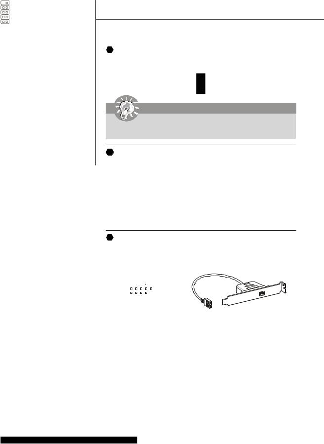
1394
- Supports 1394 by VIA VT6308
En-2
 FDD
FDD
-1 floppy port
-Supports 1 FDD with 360KB, 720KB, 1.2MB, 1.44MB and 2.88MB
 Connectors
 Back panel
-1 PS/2 mouse port
-1 PS/2 keyboard port
-2 eSATA ports (support Command Based Port Multipliers)
-6 USB 2.0 Ports
-1 LAN jack (10/100/1000)
-6 flexible audio jacks
-1 1394 port (optional)
-1 Optical S/PDIF-Out (optional)
 On-Board Pinheaders / Connectors
-3 USB 2.0 pinheaders
-1 1394 pinheader (optional)
-1 chasis intrusion connector
-1 SPDIF-out pinheader
-1 CD-in connector
-2 H/W OC pinheaders (optional)
-1 front audio pinheader
-1 serial pinheader
 Slots
Slots
-1 PCI Express x16 slot
-2 PCI Express x1 slots
-1 PCI Express x4 slot
-2 PCI slots
-Support 3.3V/ 5V PCI bus Interface
 Form Factor
- ATX (30.5cm X 24.5cm)
Mounting
- 9 mounting holes
English
En-3
 MS-7345 Mainboard
|
|
|
H |
En-20 |
G |
|
J |
|
|
|
|
|
|
|
|
|
|
En-19 |
|
En-20 |
|
|
|
|
|
|
|
|
|
I |
|
|
|
|
|
|
|
|
|
|
|
|
|
|
M |
En-20 |
|
|
|
|
|
|
|
|
En-20 |
|
|
||
A |
En-18 |
|
|
|
|
|
|
|
|
|
|
|
|
|
|
|
|
|
|
L |
En-20 |
||
|
|
|
|
|
|
|
|
|
|
||
A |
En-18 |
|
|
|
|
|
|
|
|
N |
En-20 |
|
F |
|
P |
|
|
H |
Q |
K |
En-20 |
|
|
|
En-19 En-20 |
|
|
En-20 |
En-20 |
|
|
|
|
||
|
25 |
26 |
En-16 |
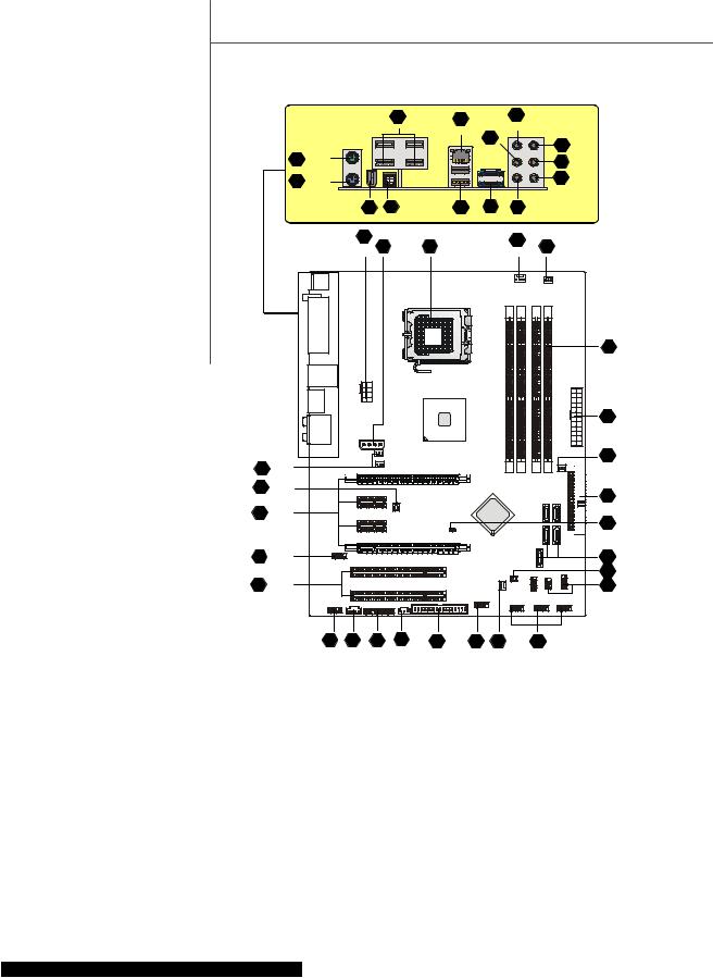
1 |
En-5 |
|
4 |
4 |
En-9 |
||
|
|
|
|||||||||
|
En-16 |
|
En-9 |
||||||||
 3
3  En-7
En-7
22 |
En-15 |
4 |
En-9 |
4 |
En-9 |
|
|
13 |
En-12 |
6 |
En-9 |
|
|
||
28 |
En-17 |
15 |
En-12 |
|
|
||
17 |
En-13 |
7 |
En-10 |
|
|
21 |
En-15 |
29 |
En-17 |
8 |
En-10 |
12 14 |
19 |
11 |
5 |
9 |
4 |
10 En-11 |
En-11 En-12 |
En-13 |
En-11 |
En-9 |
En-10 En-9 |
|
|
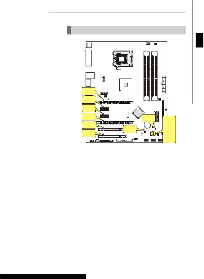
Quick Components Guide of P35 Platinum Series
(MS-7345 v1.X) Mainboard
En-4

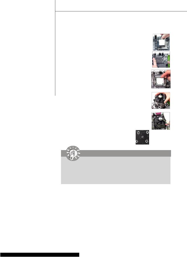
Central Processing Unit: CPU
 1
1 The mainboard supports Intel ® processor. The mainboard uses a CPU socket called Socket 775 for easy CPU installation. If you do not have the CPU cooler, consult your dealer before turning on the computer.
For the latest information about CPU, please visit http://global.msi.com.tw/index.php? func=cpuform
Important
Overheating
Overheating will seriously damage the CPU and system. Always make sure the cooling fan can work properly to protect the CPU from overheating. Make sure that you apply an even layer of thermal paste (or thermal tape) between the CPU and the heatsink to enhance heat dissipation.
Replaceing the CPU
While replacing the CPU, always turn off the ATX power supply or unplug the power supply ’s power cord from the grounded outlet first to ensure the safety of CPU.
Overclocking
This mainboard is designed to support overclocking. However, please make sure your components are able to tolerate such abnormal setting, while doing overclocking. Any attempt to operate beyond product specifications is not recommended. We do not guarantee the damages or risks caused by inadequate operation or beyond product specifications.
En-5
English
 MS-7345 Mainboard
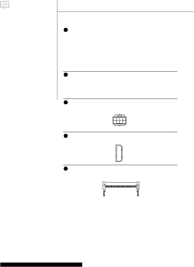
CPU & Cooler Installation Procedures for Socket 775
1.The CPU socket has a plastic cap on it to protect the contact from damage. Before you have installed the CPU, always cover it to protect the socket pin.
2.Remove the cap from lever hinge side.
3.The pins of socket reveal.
4.Open the load lever.
5.Lift the load lever up and open the load plate.
6.After confirming the CPU direction for correct mating, put down the CPU in the socket housing frame. Be sure to grasp on the edge of the CPU base. Note that the alignment keys are matched.
7.Visually inspect if the CPU is seated well into the socket. If not, take out the CPU with pure vertical motion and reinstall.
8.Cover the load plate onto the package.
9.Press down the load lever lightly onto the load plate, and then secure the lever with the hook under retention tab.
10.Align the holes on the mainboard with the cooler. Push down the cooler until its four clips get wedged into the holes of the mainboard.
11.Press the four hooks down to fasten the cooler. Then rotate the locking switch (refer to the correct direction marked on it) to lock the hooks.
12.Turn over the mainboard to confirm that the clip-ends are correctly inserted.
alignment key
Important
1.Read the CPU status in BIOS.
2.Whenever CPU is not installed, always protect your CPU socket pin with the plastic cap covered to avoid damaging.
3.Mainboard photos shown in this section are for demonstration of the CPU/ cooler installation only. The appearance of your mainboard may vary depend-
ing on the model you purchase.
En-6
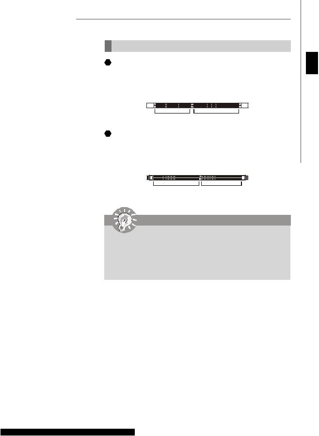
Memory
 2
2 DDR
DDR
Specification : 184-pin, 2.5v.
Single channel definition : All DIMM slots are GREEN color.
Dual channels definition : DIMM slot(s) on Channel A are marked in GREEN color. DIMM slot(s) on Channel B are marked in Purple color.
40x2=80 pin |
52x2=104 pin |
 3
3 DDR2
DDR2
Specification : 240-pin, 1.8v.
Single channel definition : All DIMM slots are GREEN color.
Dual channels definition : DIMM slot(s) on Channel A are marked in GREEN color. DIMM slot(s) on Channel B are marked in Orange color.
64x2=128 pin |
56x2=112 pin |
Important
-DDR2 memory modules are not interchangeable with DDR and the DDR2 stan dard is not backwards compatible. You should always install DDR2 memory modules in the DDR2 DIMM slots.
- In Dual-Channel mode, make sure that you install memory modules of |
the same |
type and density in different channel DIMM slots. |
|
-To enable successful system boot-up, always insert the memory modules into the
DIMM1 first.
En-7
English
 MS-7345 Mainboard
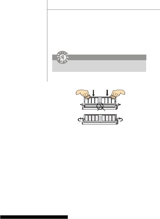
Installing Memory Modules
You can find the notch on the memory modules and the volt on the DIMM slots whether DDR or DDR2. Follow the procedures below to install the memory module properly.
1.The memory modules has only one notch on the center and will only fit in the right orientation.
2.Insert the memory module vertically into the DIMM slot. Then push it in until the
golden finger on the memory module is deeply inserted in the DIMM slot.
Important
You can barely see the golden finger if the memory module is properly inserted in the DIMM slot.
3. The plastic clip at each side of the DIMM slot will automatically close.
Volt Notch
En-8
Connectors, Jumpers, Slots
 4
4 Fan Power Connectors
The fan power connectors support system cooling fan with +12V. The CPU FAN supports Smart FAN function. When connect the wire to the connectors, always take note that the red wire is the positive and should be connected to the +12V, the black wire is Ground and should be connected to GND. If the mainboard has a System Hardware Monitor chipset on-board, you must use a specially designed fan with speed sensor to take advantage of the fan control.
|
Control |
SENSOR or NC |
|
|
SENSOR |
|
+12V |
|
+12V |
|
GND |
|
GND |
|
SYS FAN/ NB FAN/ |
|
|
|
|
|
CPU FAN |
|
POWER FAN |
|
Important |
|
|
1. |
Please refer to the recommended CPU fans at processor ’s official website or |
||
|
consult the vendors for proper CPU cooling fan. |
||
2. |
CPUFAN supports fan control. You can install |
Dual Core Center utility that |
|
will automatically control the CPU fan speed according to the actual CPU temperature.
3. Fan cooler set with 3 or 4 pins power connector are both available for CPUFAN.
 5
5 Floppy Disk Drive Connector
This connector supports 360KB, 720KB, 1.2MB, 1.44MB or 2.88MB floppy disk drive.
 6
6 IDE connector
This connector supports IDE hard disk drives, optical disk drives and other IDE devices.
Important
If you install two IDE devices on the same cable, you must configure the drives separately to Master/ Slave mode by setting jumpers. Refer to IDE device ’s documentation supplied by the vendors for jumper setting instructions.
En-9
English
 MS-7345 Mainboard
 7
7 Serial ATA Connector
This connector is a high-speed Serial ATA interface port. Each connector can connect to one Serial ATA device.
Important
Please do not fold the Serial ATA cable into 90-degree angle. Otherwise, data loss may occur during transmission.
8 Front Panel Connectors
These connectors are for electrical connection to the front panel switches and LEDs. The JFP1 is compliant with Intel ® Front Panel I/O Connectivity Design Guide.
10 9 |
|
|
|
|
|
|
|
|
|
|
|||||||||
Power |
|
|
|
|
|
|
|
|
|
Reset |
|
|
8 7 |
|
|
||||
|
|
|
|
|
|
|
|
|
|
|
|
|
|||||||
Switch |
|
|
|
|
|
|
|
Switch |
Speaker |
|
|
|
|
|
|
||||
Power |
|
|
|
|
|
|
|
|
|
HDD |
|
|
|
|
|
|
Power LED |
||
|
|
|
|
|
|
||||||||||||||
LED |
|
|
|
|
|
|
|
|
|
LED |
|
|
|
|
|
|
|
||
2 1 |
|
|
|
|
|
2 1 |
|
|
|||||||||||
|
|
|
|
|
JFP1 |
|
|
|
|
|
JFP2 |
||||||||
 9
9 IEEE1394 Connector (Green)
This connector allows you to connect the IEEE1394 device via an optional IEEE1394 bracket.
|
TPA- |
Ground |
TPB- |
Cablepower Ground |
|||
2 |
|
|
|
|
|
|
|
|
|
|
|
|
10 |
||
1 |
|
|
|
|
|
9 |
|
|
|
|
|
|
|
|
|
|
|
|
|
|
|
|
|
|
TPA+ |
Ground |
TPB+ |
Cablepower Key(no pin) |
|||
IEEE1394Bracket
(Optional)
En-10
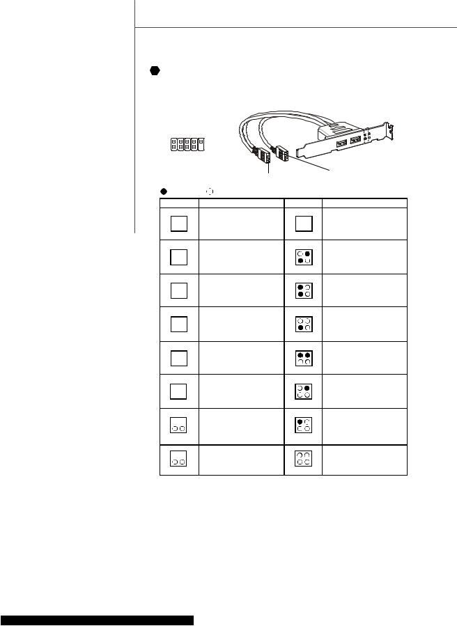
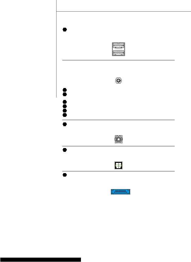
10 Front USB Connector (Yellow)
This connector, compliant with Intel ® I/O Connectivity Design Guide, is ideal for con-
necting high-speed USB interface peripherals such as |
USB HDD, digital cameras, MP3 |
||
players , printers , modems and the like . |
|
||
VCC USB1- |
USB1+ |
GND USBOC |
(Optional) |
|
|
|
USB 2.0 Bracket |
2 |
|
10 |
|
1 |
|
9 |
|
VCC USB0- |
USB0+ |
GND (no pin) |
|
|
|
Key |
|
Important
Note that the pins of VCC and GND must be connected correctly to avoid possible damage.
 11 S/PDIF-Out Connector or S/PDIF-In Connector
This connector is used to connect S/PDIF (Sony & Philips Digital Interconnect Format) interface for digital audio transmission.
GND |
GND |
SPDIF_out |
SPDIF_in |
VCC |
VCC |
SPDIF_Out |
SPDIF_In |
|
|
|
|
|
|
|
|
SPDIF Bracket (Optional) |
|
12 Front Panel Audio Connector (Azalia Spec) |
|
|
|||
This connector allows you to connect the front panel audio and is compliant with Intel |
® |
||||
|
|
|
|
|
|
Front Panel I/O Connectivity Design Guide. |
|
|
|
||
|
Ground |
Presence# MIC_JD |
NC(No pin) |
LINE out_JD |
|
|
2 |
|
|
10 |
|
|
1 |
MIC R LINE out R |
Front JD |
9 |
|
|
MIC _L |
LINE out_L |
|
||
En-11
English
 MS-7345 Mainboard
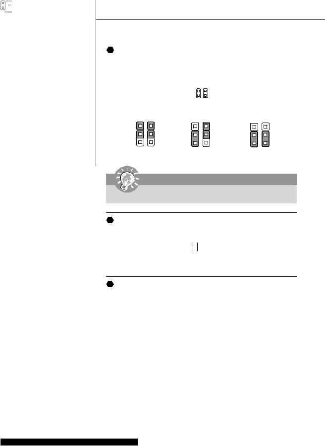
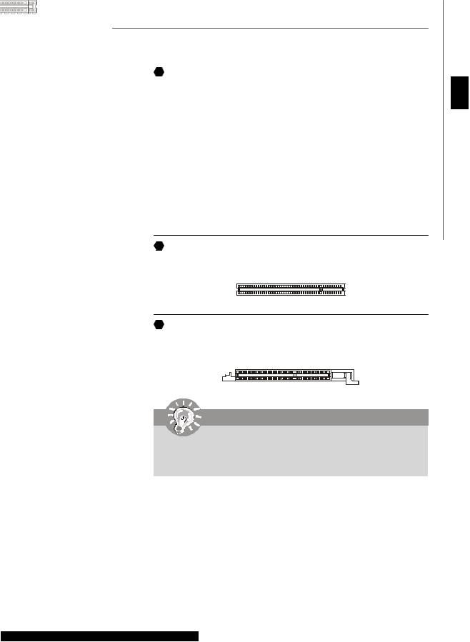
13 Hardware Overclock FSB Jumpers: JB1, JB2 (optional)
You can overclock the FSB to increase the processor frequency by changing the jumpers JB1 and JB2. Follow the instructions below to set the FSB.
1 

JB1 JB2
1 |
1 |
1 |
3 |
3 |
3 |
200 MHz |
266 MHz |
333 MHz |
Important
Make sure that you power off the system before changing the jumpers
14 CD-In Connector
This connector is provided for external audio input.
L GND R
15 Chassis Intrusion Connector
This connector connects to the chassis intrusion switch cable. If the chassis is opened, the chassis intrusion mechanism will be activated. The system will record this status and show a warning message on the screen. To clear the warning, you must enter the BIOS utility and clear the record.
1CINTRU
2GND
En-12
16 Infrared Module Connector
This connector allows you to connect to infrared module and is compliant with Intel |
® |
|
|
||
Front Panel I/O Connectivity Design Guide. You must configure the setting through the |
|
|
BIOS setup to use the infrared function. |
|
|
1 2 |
NC |
|
NC |
|
|
VCC5 |
Ground |
|
IRTX |
IRRX |
|
5 6 |
|
|
|
|
|
17 Serial Port Connector |
|
|
This connector is a 16550A high speed communication port that sends/receives 16 |
|
|
bytes FIFOs. You can attach a serial device. |
|
|
DSR RTS CTS RI (9) |
|
|
6 |
5 |
|
1 |
|
|
DCD SIN SOUT |
DTR Ground |
|
18 TV-Out Connector
This connector is for you to attach an optional TV-Out bracket that offers some types of TV-Out connectors. Select the appropriate one to connect to an television.
|
1 4 |
Ground |
COMP or CVBS |
Yout |
Ground (5) |
Cout |
3 |
|
19 VoIP Card Connector
This connector connects to the VoIP card. Please refer to the instruction of the VoIP card.
English
En-13
 MS-7345 Mainboard
20 D-Bracket ™ 2 Connector
This connector is for you to connect to the D-Bracket ™2 which integrates four LEDs and USB ports. It allows users to identify system problems through 16 various combinations
of LED signals.
|
|
D-Bracket ™ 2 |
|
|
(Optional) |
DBR1 DBR2 DBR3 DBR4 NC |
|
|
2 |
10 |
|
1 |
9 |
|
DBG1 DBG2 DBG3 DBG4 |
Key |
|
|
Connected to USB connector |
Connected to D- |
|
Bracket 2 connector |
|
Red
LED Signal
1 
 2
2
3 
 4
4
1 
 2
2
3 
 4
4
1 
 2
2
3 
 4
4
1 
 2
2
3 
 4
4
1 
 2
2
3 
 4
4
1 
 2
2
3 
 4
4
1 
 2
2
3 
 4
4
1 
 2
2
3 
 4
4
Green
Description
SystemPowerON
The D-LED will hang here if the processor is damaged or not installedproperly.
EarlyChipset Initialization
MemoryDetectionTest
Testingonboard memory size. The D-LEDwill hangif the memorymodule is damaged or not installed properly.
DecompressingBIOSimagetoRAM for fast booting.
Initializing Keyboard Controller.
Testing VGA BIOS
This will start writing VGA sign-on messageto the screen.
Processor Initialization
This will show informationregarding the processor (like brandname, systembus,etc...)
Testing RTC (Real Time Clock)
LED Signal |
Description |
InitializingVideoInterface
1 
 2 This will start detecting CPU clock,
3 
 4 checkingtypeofvideoonboard.Then, detectandinitializethevideoadapter.
1 |
2 |
BIOS Sign On |
|
This will start showing information |
|||
3 |
4 |
about logo, processor brandname, |
|
etc... |
|||
|
|
||
1 |
2 |
Testing Base andExtendedMemory |
|
Testing base memory from 240K to |
|||
3 |
4 |
640K and extendedmemory above |
|
1MB using various patterns. |
|||
|
|
||
1 |
2 |
Assign Resources to all ISA. |
|
3 |
4 |
||
|
|||
1 |
2 |
Initializing Hard Drive Controller |
|
This will initialize IDE drive and |
|||
3 |
4 |
||
controller. |
|||
1 |
2 |
Initializing Floppy Drive Controller |
|
This will initialize Floppy Drive and |
|||
3 |
4 |
||
controller. |
|||
1 |
2 |
BootAttempt |
|
3 |
4 |
This will set low stack andboot via |
|
INT19h. |
|||
|
|
||
1 |
2 |
OperatingSystemBooting |
|
3 |
4 |
||
|
En-14
 21 Clear CMOS Button
The CMOS RAM onboard has a power supply from external battery to keep the data of system configuration. With the CMOS RAM, the system can automatically boot OS every time it is turned on. If you want to clear the system configuration, use the button to clear data. Press the button to clear the data.
Important
Make sure that you power off the system before clearing CMOS data.
Power Supply Attachment
Before inserting the power supply connector, always make sure that all components are installed properly to ensure that no damage will be caused. All power connectors on the mainbnoard have to connect to the ATX power supply and have to work together to ensure stable operation of the mainboard.
22 ATX 24-Pin Power Connector
This connector allows you to connect an ATX 24-pin power supply. To connect the ATX 24-pin power supply, make sure the plug of the power supply is inserted in the proper orientation and the pins are aligned. Then push down the power supply firmly into the connector.
You may use the 20-pin ATX power supply as you like. If you ’d like to use the 20-pin ATX power supply, please plug your power supply along with pin 1 & pin 13.
|
12 24 |
+3.3V |
GND |
+12V |
+5V |
+12V |
+5V |
5VSB |
+5V |
PWROK |
NC |
GND |
GND |
+5V |
GND |
GND |
GND |
+5V |
PS-ON# |
GND |
GND |
+3.3V |
-12V |
+3.3V |
+3.3V |
|
1 13 |
En-15
English
 MS-7345 Mainboard
 23 ATX 20-Pin Power Connector
This connector allows you to connect an ATX 20-pin power supply. To connect the ATX 20-pin power supply, make sure the plug of the power supply is inserted in the proper orientation and the pins are aligned. Then push down the power supply firmly into the connector.
5V 5V -5V GND GND GND PS-ON |
GND -12V 3.3V |
10 20 |
1 11 |
12V 5VSB PWR OK GND 5V GND 5V |
GND 3.3V 3.3V |
 24 ATX 12V Power Connector (2x2-Pin)
This 12V power connector is used to provide power to the CPU.
2 1
GND GND
12V 12V
4 3
 25 ATX 12V Power Connector (2x4-Pin)
This 12V power connector is used to provide power to the CPU.
|
+12V |
8 |
5 |
4 |
1 |
GND
 26 ATX 12V Power Connector (1x4-Pin)
This 12V power connector is used to provide power to the graphics card.
1  5V
5V
2  GND
GND
3  GND
GND
4  12V
12V
 27 NV SLI Connector
This connector is used to configure the SLI switch card to SLI or non-SLI mode.
En-16
 28 PCI Express Slot (x16/ x4/ x1)
The PCI Express slot supports the PCI Express interface expansion card. The PCI Express x 16 supports up to 4.0 GB/s transfer rate.
The PCI Express x 8 supports up to 2.0 GB/s transfer rate. The PCI Express x 4 supports up to 1.0 GB/s transfer rate. The PCI Express x 1 supports up to 250 MB/s transfer rate.
PCIExpress x 16Slot
PCI Expressx 4Slot
PCI Expressx 1Slot
 29 PCI (Peripheral Component Interconnect) Slot
The PCI slot supports LAN card, SCSI card, USB card, and other add-on cards that comply with PCI specifications.
30 AGP (Accelerated Graphics Port) Slot
The AGP slot allows you to insert the AGP graphics card. AGP is an interface specification designed for the throughput demands of 3D graphics. It introduces a 66MHz, 32-bit channel for the graphics controller to directly access main memory.
English
Important
When adding or removing expansion cards, make sure that you unplug the power supply first. Meanwhile, read the documentation for the expansion card to configure any necessary hardware or software settings for the expansion card, such as jumpers, switches or BIOS configuration.
En-17

 MS-7345 Mainboard
Back Panel
 A
A Mouse/Keyboard
The standard PS/2 ® mouse/keyboard DIN connector is for a PS/2 ® mouse/keyboard.
PS/2 Mouse connector (Green/ 6-pin female)
PS/2 Keyboard connector (Purple/ 6-pin female)
 B
B Parallel Port
A parallel port is a standard printer port that supports Enhanced Parallel Port (EPP) and Extended Capabilities Parallel Port (ECP) mode.
13 |
1 |
|
(25-pin female connector) |
25 |
14 |
 C
C Serial Port
The serial port is a 16550A high speed communications port that sends/ receives 16 bytes FIFOs. You can attach a serial mouse or other serial devices directly to the connector.
1 5
(9-Pin Male Connector)
6 9
 D
D VGA Port
The DB15-pin female connector is provided for monitor.
5 1
(15-Pin Female DIN Connector)
15 11
En-18
 E
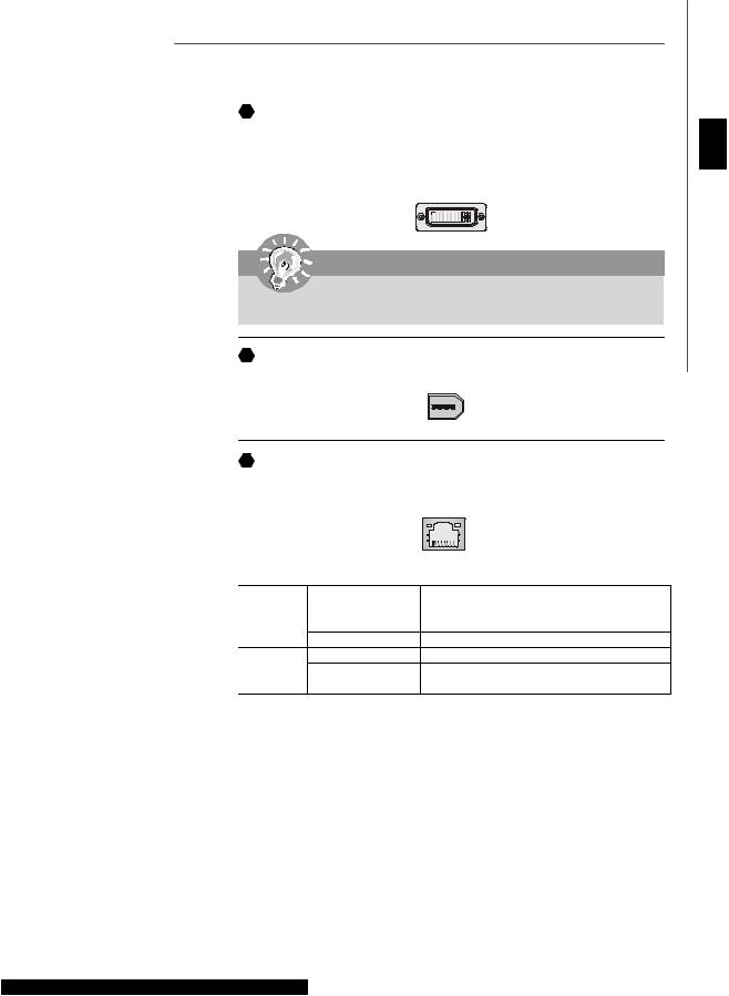
E DVI Port
The DVI (Digital Visual Interface) connector allows you to connect an LCD monitor. It provides a high-speed digital interconnection between the computer and its display device. To connect an LCD monitor, simply plug your monitor cable into the DVI connector, and make sure that the other end of the cable is properly connected to your monitor (refer to your monitor manual for more information.)
1 8
17 24
Important
Please note that the DVI connector does not support connecting the D-Sub to DVI converter.
 F
F 1394 Port
The IEEE1394 port on the back panel provides connection to IEEE1394 devices.
 G
G LAN
LAN
The standard RJ-45 LAN jack is for connection to the Local Area Network (LAN). You can connect a network cable to it.
English
LED |
Color |
LED State |
Condition |
|
|
Off |
LANlink is not established. |
Left |
Orange |
On(steady state) |
LANlinkis established. |
|
|
On (brighter & pulsing) |
ThecomputeriscommunicatingwithanothercomputerontheLAN. |
|
Green |
Off |
10 Mbit/sec data rate is selected. |
Right |
|
On |
100 Mbit/sec data rate is selected. |
|
Orange |
On |
1000 Mbit/sec datarate is selected. |
En-19
 MS-7345 Mainboard
 H
H USB Port
The USB (Universal Serial Bus) port is for attaching USB devices such as keyboard, mouse, or other USB-compatible devices.
Audio Port Connectors
These audio connectors are used for audio devices. You can differentiate the color of the audio jacks for different audio sound effects.
I |
Line-Out (Green) - Line Out, is a connector for speakers or headphones. |
|
J |
Line-In (Blue) |
- Line In / Side-Surround Out in 7.1 channel mode, is used for ex- |
|
ternal CD player, tapeplayer or other audio devices. |
|
K |
MIC (Pink) - Mic In, is a connector for microphones. |
|
L |
CS-Out (Orange) - Center/ Subwoofer Out in 5.1/ 7.1 channel mode. |
|
M |
RS-Out (Black) |
- Rear-Surround Out in 4/ 5.1/ 7.1 channel mode. |
N |
SS-Out (Gray) |
- Side-Surround Out 7.1 channel mode. |
 O
O Coaxial S/PDIF-out
This S/PDIF (Sony & Philips Digital Interconnect Format) connector is provided for digital audio transmission to external speakers through a coaxial cable.
 P
P Optical S/PDIF-out
This S/PDIF (Sony & Philips Digital Interconnect Format) connector is provided for digital audio transmission to external speakers through an optical fiber cable.
 Q
Q External SATA Port
This eSATA (External Serial ATA) port is used to connect the external SATA device. You can also use the optional external SATA cable to connect SATA device and eSATA port.
En-20
LED Status Indicators
English
LED11 |
|
|
LED15 |
|
|
LED16 |
|
|
LED12 |
LED1 |
LED20 |
|
||
|
|
LED10 |
LED13 |
|
LED19 |
|
LED3 |
LED9 |
|
LED18 |
|
LED14 |
|
|
|
LED8 |
|
|
|
LED17 |
|
|
LED7 |
Name |
Status |
|
|
LED1 |
Lights when system is power-on. |
|
|
LED3 |
Lights when system is on standby mode. |
|
|
LED11 |
Lights when PCI_E3 slot is functional. |
|
|
LED12 |
Lights when PCI_E4 slot is functional. |
|
|
LED13 |
Lights when PCI1 slot is functional. |
|
|
LED14 |
Lights when PCI2 slot is functional. |
|
|
LED15 |
Lights when PCI_E1 slot is functional. |
|
|
LED16 |
Lights when PCI_E2 slot is functional. |
|
|
En-21
 MS-7345 Mainboard
LED 7, 8, 9 ,10, 17, 18, 19, 20
These four LEDs allow users to identify system problems through 16 various combinations of LED signals.
LED20
LED10
LED19
LED9
LED18
LED8
LED17
LED7
 Group4
 Group3
 Group2
 Group1
|
|
|
|
Red |
|
Green |
|
LED Signal |
|
Description |
|||
|
|
|
Group4 |
SystemPowerON |
||
|
|
|||||
|
|
|
Group3 |
The D-LED will hang here if the |
||
|
|
|
Group2 |
processor is damaged or not in- |
||
|
|
|
Group1 |
stalledproperly. |
||
|
|
|||||
|
|
|
Group4 |
|
|
|
|
|
|
|
|
||
|
|
|
Group3 |
EarlyChipset Initialization |
||
|
|
|
Group2 |
|
|
|
|
|
|
Group1 |
MemoryDetectionTest |
||
|
|
|
Group4 |
|||
|
|
|
Group3 |
Testingonboard memory size. The |
||
|
|
|
Group2 |
D-LEDwill hangif the memorymod- |
||
|
|
|
Group1 |
ule is damaged or not installed |
||
|
|
|
|
|
properly. |
|
|
|
|
Group4 |
|
|
|
|
||
|
|
|
Group3 |
DecompressingBIOSimagetoRAM |
|
|
|
Group2 |
for fast booting. |
|
|
|||
|
|
|
Group1 |
|
|
|
|
Group4 |
|
|
|
|
||
|
|
|
Group3 |
Initializing Keyboard Controller. |
|
|
|||
|
|
|
Group2 |
|
|
|
|
Group1 |
|
|
|
|
Group4 |
Testing VGA BIOS |
|
|
|||
|
|
|||
|
|
|
Group3 |
This will start writing VGA sign-on |
|
|
|
Group2 |
|
|
|
|
Group1 |
messageto the screen. |
|
|
|
Group4 |
Processor Initialization |
|
|
|||
|
|
|
Group3 |
This will show informationregarding |
|
|
|
Group2 |
the processor (like brandname, sys- |
|
|
|
Group1 |
tembus,etc...) |
|
|
|||
|
|
|
Group4 |
|
|
|
|
|
|
|
|
|
Group3 |
Testing RTC (Real Time Clock) |
|
|
|
||
|
|
|
Group2 |
|
|
|
|
Group1 |
|
LED Signal |
Description |
||||
|
|
|
|
Group4 |
InitializingVideoInterface |
|
|
|
|
Group3 |
This will start detecting CPU clock, |
|
|
|
|
Group2 |
checkingtypeofvideoonboard.Then, |
|
|
|
|
Group1 detectandinitializethevideoadapter. |
|
|
|
|
|
Group4 |
BIOS Sign On |
|
|
|
|
Group3 |
This will start showing information |
|
|
|
|
Group2 |
about logo, processor brandname, |
|
|
|
|
Group1 |
etc... |
|
|
|
|
Group4 |
Testing Base andExtendedMemory |
|
|
||||
|
|
|
|
Group3 |
Testing base memory from 240K to |
|
|
||||
|
|
|
|
Group2 |
640K and extendedmemory above |
|
|
|
|
Group1 |
1MB using various patterns. |
|
|
||||
|
|
|
|
Group4 |
|
|
|
|
|
||
|
|
|
|
Group3 |
Assign Resources to all ISA. |
|
|
|
|||
|
|
|
|
Group2 |
|
|
|
|
|
Group1 |
Initializing Hard Drive Controller |
|
|
|
|
Group4 |
|
|
|
|
|||
|
|
|
|
Group3 |
This will initialize IDE drive and |
|
|
|
|
Group2 |
controller. |
|
|
|
|||
|
|
|
|
Group1 |
|
|
|
|
|
Group4 |
Initializing Floppy Drive Controller |
|
|
|
|||
|
|
|
|
Group3 |
This will initialize Floppy Drive and |
|
|
|
|
Group2 |
controller. |
|
|
|
|||
|
|
|
|
Group1 |
|
|
|
|
|
Group4 |
BootAttempt |
|
|
|
|||
|
|
|
|
Group3 |
This will set low stack andboot via |
|
|
|
|||
|
|
|
|
Group2 |
INT19h. |
|
|
|
|
Group1 |
|
|
|
|
|
Group4 |
|
|
|
|
|
|
|
|
|
|
|
Group3 |
OperatingSystemBooting |
|
|
|
|
||
|
|
|
|
Group2 |
|
Group1
En-22
 Loading...