


SPLIT-TYPE, HEAT PUMP AIR CONDITIONERS
February 2009
No. OCH450
TECHNICAL & SERVICE MANUAL
Indoor unit [Model names]
PCFY-P15NKMU-E
PCFY-P24NKMU-E
PCFY-P30NKMU-E
PCFY-P36NKMU-E


 R410A
R410A 

 R22
R22
[Service Ref.]
PCFY-P15NKMU-E PCFY-P24NKMU-E PCFY-P30NKMU-E PCFY-P36NKMU-E
Note:
•This manual describes only service data of the indoor units.
•RoHS compliant products have <G> mark on the spec name plate.
CONTENTS
1. |
PART NAMES AND FUNCTIONS ..........2 |
||
2. |
SPECIFICATION .....................................4 |
||
3. |
OUTLINES AND DIMENSIONS..............8 |
||
4. |
WIRING DIAGRAM............................... |
11 |
|
5. REFRIGERANT SYSTEM DIAGRAM |
........ |
12 |
|
|
............... |
13 |
|
6. MICROPROCESSOR CONTROL |
|
||
7. |
TROUBLESHOOTING .......................... |
20 |
|
8. |
DISASSEMBLY PROCEDURE............. |
29 |
|
PARTS CATALOG (OCB450)
INDOOR UNIT
Model name indication
1 
 PART NAMES AND FUNCTIONS
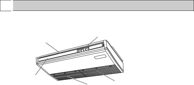
 Indoor unit
Louver
Air outlet
Vane
|
Filter |
Air intake |
(Inside of Air intake) |
2
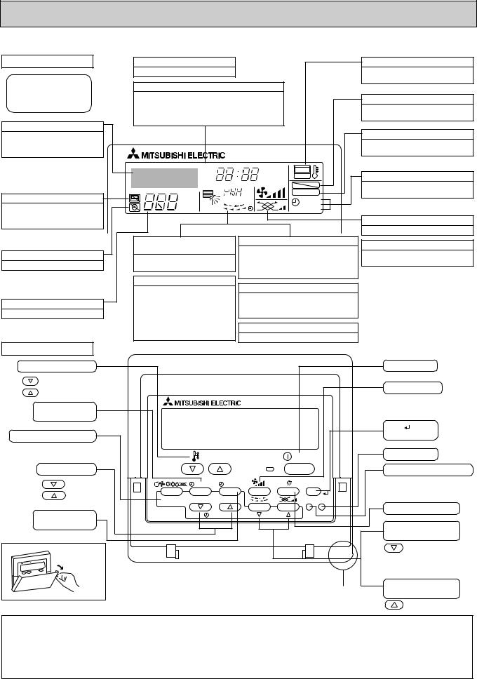
 Wired remote controller
Display Section
For purposes of this explanation, all parts of the display are shown as lit. During actual operation, only the relevant items will be lit.
Identifies the current operation
Shows the operating mode, etc. *Multilanguage display is available.
“Centrally Controlled” indicator
Indicates that operation from the remote controller has been prohibited by a master controller.
“Timer is Off” indicator
Indicates that the timer is off.
Temperature Setting
Shows the target temperature.
Day-of-Week
Shows the current day of the week.
Time/Timer Display
Shows the current time, unless the simple or Auto Off timer is set.
If the simple or Auto Off timer is set, the time to be switched off is shown.
TIME SUN MON TUE WED THU FRI SAT |
||
TIMER |
Hr |
ON |
AFTER |
AFTER |
OFF |
ERROR CODE |
|
FUNCTION |
°F°C |
|
FILTER |
°F°C |
|
|
|
WEEKLY |
|
ONLY1Hr. |
|
SIMPLE |
|
AUTO OFF |
|
Up/Down Air Direction indicator
The indicator  shows the direction of the outcoming airflow.
“One Hour Only” indicator
Displayed if the airflow is set to Low or downward during COOL or DRY mode. (Operation varies according to model.)
The indicator goes off in one hour, at which time the airflow direction also changes.
Room Temperature display
Shows the room temperature. The room temperature display range is 46–102°F. The display blinks if the temperature
is less than 46°F or 102°F or more.
Louver display
Indicates the action of the swing louver. Does not appear if the louver is not running.
 (Power On indicator)
Indicates that the power is on.
“Sensor” indication
Displayed when the remote controller sensor is used.
“Locked” indicator
Indicates that remote controller buttons have been locked.
“Clean The Filter” indicator
To be displayed on when it is time to clean the filter.
Timer indicators
The indicator comes on if the corresponding timer is set.
Fan Speed indicator
Shows the selected fan speed.
Ventilation indicator
Appears when the unit is running in Ventilation mode.
Operation Section |
|
|
|
Temperature setting buttons |
|
|
|
Down |
|
|
|
Up |
|
|
|
Timer Menu button |
|
|
|
(Monitor/Set button) |
|
|
|
Mode button (Return button) |
|
|
|
|
|
TEMP. |
|
Set Time buttons |
|
|
|
Back |
|
MENU |
ON/OFF |
Ahead |
BACK |
MONITOR/SET |
DAY |
|
|||
Timer On/Off button |
PAR-21MAA |
CLOCK |
|
(Set Day button) |
|
|
|
Opening the |
|
|
|
lid |
|
|
|
|
ON/OFF |
|
|
FILTER |
|
|
CHECK |
TEST |
OPERATION |
CLEAR |
|
Built-in temperature sensor
ON/OFF button
Fan Speed button
Filter button (<Enter> button)
Test Run button
Check button (Clear button)
Airflow Up/Down button
Louver button
( Operation button)
To return operation number
Ventilation button
( Operation button)
To go to next operation number
Note:
●“PLEASE WAIT” message
This message is displayed for approximately 3 minutes when power is supplied to the indoor unit or when the unit is recovering from a power failure.
●“NOT AVAILABLE” message
This message is displayed if an invalid button is pressed (to operate a function that the indoor unit does not have).
If a single remote controller is used to operate multiple indoor units simultaneously that are different types, this message will not be displayed as far as any of the indoor units is equipped with the function.
3
2 |
|
|
SPECIFICATION |
|
|
|
|
|
|
|
|
|
|||||
2-1. SPECIFICATIONS |
|
|
|
|
|
|
|
|
|
|
|
||||||
|
|
|
|
|
|
|
|
|
|
|
|
|
|||||
Model |
|
|
|
|
|
PCFY-P15NKMU-E |
PCFY-P24NKMU-E |
|
PCFY-P30NKMU-E |
|
|
PCFY-P36NKMU-E |
|||||
Power source |
|
|
|
|
|
|
|
1-phase 208/230V 60Hz |
|
|
|
|
|||||
Cooling capacity |
|
|
*1 |
kW |
4.4 |
|
7.0 |
|
|
8.8 |
|
|
|
10.6 |
|||
(Nominal) |
|
|
|
*1 |
Btu/h |
15,000 |
24,000 |
|
30,000 |
|
36,000 |
||||||
|
|
|
|
Power input |
|
kW |
0.03 |
|
0.04 |
|
|
0.09 |
|
|
|
0.11 |
|
|
|
|
|
Current input |
A |
0.35 |
|
0.41 |
|
|
0.83 |
|
|
|
0.97 |
||
Heating capacity |
|
|
*2 |
kW |
5.0 |
|
7.9 |
|
|
10.0 |
|
|
|
11.7 |
|||
(Nominal ) |
|
|
|
*2 |
Btu/h |
17,000 |
27,000 |
|
34,000 |
|
40,000 |
||||||
|
|
|
|
Power input |
|
kW |
0.03 |
|
0.04 |
|
|
0.09 |
|
|
|
0.11 |
|
|
|
|
|
Current input |
A |
0.35 |
|
0.41 |
|
|
0.83 |
|
|
|
0.97 |
||
External finish |
|
|
|
|
|
|
|
MUNSELL (6.4Y 8.9/0.4) |
|
|
|
|
|||||
External dimensions H x W x D |
|
mm |
230×960×680 |
230×1280×680 |
|
|
230×1600×680 |
|
|||||||||
|
|
|
|
|
|
|
in. |
9-1/16×37-13/16×26-3/4 |
9-1/16×50-3/8×26-3/4 |
|
|
9-1/16×63×26-3/4 |
|
||||
Net weight |
|
|
|
|
kg (lb) |
24 (53) |
32 (71) |
|
36 (79) |
|
38 (84) |
||||||
Heat exchanger |
|
|
|
|
|
Cross fin (Aluminum |
fin and copper tube) |
|
|
|
|
||||||
FAN |
|
Type x quantity |
|
Sirocco fan × 2 |
Sirocco fan × 3 |
|
|
Sirocco fan × 4 |
|
||||||||
|
|
|
|
External |
|
Pa |
|
|
|
0 |
|
|
|
|
|
||
|
|
|
|
static press. |
|
mmH2O |
|
|
|
0 |
|
|
|
|
|
||
|
|
|
|
Motor type |
|
|
|
|
DC motor |
|
|
|
|
|
|||
|
|
|
|
Motor output |
kW |
0.090 |
0.095 |
|
|
|
0.160 |
|
|||||
|
|
|
|
Driving mechanism |
|
|
|
Direct-driven by motor |
|
|
|
|
|
||||
|
|
|
|
Airflow rate |
|
m3/min |
10-11-12-13 |
14-15-16-18 |
|
20-22-25-28 |
|
21-24-27-31 |
|||||
|
|
|
|
(Low-Mid2-Mid1-High) |
L/s |
167-183-200-217 |
233-250-267-300 |
|
333-367-417-467 |
|
350-400-450-517 |
||||||
|
|
|
|
|
|
|
cfm |
353-388-424-459 |
494-530-565-636 |
|
703-777-883-989 |
|
742-847-953-1095 |
||||
Noise level (Low-Mid2-Mid1-High) |
dB <A> |
29-32-34-36 |
31-33-35-37 |
|
34-37-40-43 |
|
36-39-42-44 |
||||||||||
(measured in anechoic room) |
|
|
|
|
|
|
|
|
|
|
|
|
|||||
Insulation material |
|
|
|
|
|
|
Polyeter sheet |
|
|
|
|
|
|||||
Air filter |
|
|
|
|
|
|
|
PP honeycomb |
|
|
|
|
|
||||
Protection device |
|
|
|
|
|
|
|
Fuse |
|
|
|
|
|
||||
Refrigerant control device |
|
|
|
|
|
LEV |
|
|
|
|
|
||||||
Connectable outdoor unit |
|
|
|
|
R410A, R22 CITY MULTI |
|
|
|
|
||||||||
Diameter of |
|
Liquid |
(R410A) |
mm(in.) |
ø6.35 (ø1/4) Flare |
ø9.52 |
(ø3/8) Flare |
|
ø9.52 |
(ø3/8) Flare |
|
ø9.52 |
(ø3/8) Flare |
||||
refrigerant pipe |
|
|
|
(R22) |
|
ø6.35 (ø1/4) Flare |
ø9.52 |
(ø3/8) Flare |
|
ø9.52 |
(ø3/8) Flare |
|
ø9.52 |
(ø3/8) Flare |
|||
|
|
|
|
Gas |
|
(R410A) |
mm(in.) |
ø12.7 (ø1/2) Flare |
ø15.88 |
(ø5/8) Flare |
|
ø15.88 |
(ø5/8) Flare |
|
ø15.88 |
(ø5/8) Flare |
|
|
|
|
|
|
|
(R22) |
|
ø12.7 (ø1/2) Flare |
ø15.88 |
(ø5/8) Flare |
|
ø15.88 |
(ø5/8) Flare |
|
|
ø19.05(ø3/4) Flare*3 |
|
Field drain pipe size |
|
|
mm(in.) |
|
|
O.D. |
26mm (1) |
|
|
|
|
|
|||||
Standard |
|
Document |
|
|
|
Installation Manual, Instruction Book |
|
|
|
|
|||||||
attachment |
|
|
|
|
|
|
|
|
|
|
|
|
|
|
|
||
|
Accessory |
|
|
|
|
Drain joint socket |
|
|
|
|
|
||||||
|
|
|
|
|
|
|
|
|
|
|
|
|
|||||
|
|
|
|
|
|
|
|
|
|
|
|
|
|||||
Optional parts |
|
Drain pump kit |
|
PAC-SH83DM-E |
|
|
|
PAC-SH84DM-E |
|
|
|
|
|||||
|
|
|
|
High efficiency filter |
|
PAC-SH88KF-E |
PAC-SH89KF-E |
|
|
PAC-SH90KF-E |
|
||||||
|
|
|
|
External heater adapter |
|
|
PAC-YU25HT |
|
|
|
|
|
|||||
|
|
|
|
i-see Sensor |
|
|
|
PAC-SH91MK-E |
|
|
|
|
|
||||
|
|
|
|
Wireless remote controller with i-see Sensor |
|
|
PAR-SA92MW-E |
|
|
|
|
|
|||||
|
|
|
|
Wireless remote controller kit |
|
|
PAR-SL93B-E |
|
|
|
|
|
|||||
Remarks |
|
Installation |
|
|
Details on foundation work, insulation work, electrical wiring, power source switch, and other items shall be referred to the |
||||||||||||
|
|
|
|
|
|
|
|
Installation Manual. |
|
|
|
|
|
|
|
|
|
|
|
|
|
|
|
|
|
|
|
|
|
||||||
Note : |
|
*1 Nominal cooling conditions |
*2 Nominal heating conditions |
*3 Connect the joint |
|
|
|
Unit converter |
|||||||||
|
|
Indoor : |
80°FDB/67°FWB (26.7°CDB/19.4°CWB) 70°FDB(21°CDB) |
|
(purchased locally) for R22 |
|
|
kcal/h |
= kW × 860 |
||||||||
|
|
Outdoor : |
95°FDB (35°CDB) |
47°FDB/43°FWB (8.3°CDB/6.1°CWB) |
|
|
|
|
|
Btu/h |
= kW × 3,412 |
||||||
|
|
|
|
|
|
|
cfm |
= m3/min × 35.31 |
|||||||||
|
Pipe length : |
25 ft. (7.6 m) |
|
25 ft. (7.6 m) |
|
|
|
|
|
|
|
||||||
|
|
|
|
|
|
|
|
|
lb |
= kg/0.4536 |
|||||||
Level difference : |
0 ft (0 m) |
|
|
0 ft (0 m) |
|
|
|
|
|
|
|
||||||
|
|
|
|
|
|
|
|
|
*Above specification data is |
||||||||
* Due to continuing improvement, above specification may be subject to change without notice. |
|
|
|
|
|
|
|||||||||||
|
|
|
|
|
|
subject to rounding variation. |
|||||||||||
|
|
|
|
|
|
|
|
|
|
|
|
|
|
|
|
|
|
4
2-2. ELECTRICAL PARTS SPECIFICATIONS
Service Ref. |
Symbol |
PCFY-P15NKMU-E |
|
PCFY-P24NKMU-E |
PCFY-P30NKMU-E |
|
|
|
|||||
Parts name |
|
PCFY-P36NKMU-E |
||||
|
|
|
|
|||
|
|
|
|
|
||
Room temperature |
TH21 |
Resistance 30°F/15.8kΩ, 50°F/9.6kΩ, 70°F/6.0kΩ, 80°F/4.8kΩ, 90°F/3.9kΩ, 100°F/3.2kΩ |
||||
thermistor |
||||||
|
|
|
|
|
||
|
|
|
||||
Liquid pipe thermistor |
TH22 |
Resistance 30°F/15.8kΩ, 50°F/9.6kΩ, 70°F/6.0kΩ, 80°F/4.8kΩ, 90°F/3.9kΩ, 100°F/3.2kΩ |
||||
|
|
|
||||
Gas pipe thermistor |
TH23 |
Resistance 30°F/15.8kΩ, 50°F/9.6kΩ, 70°F/6.0kΩ, 80°F/4.8kΩ, 90°F/3.9kΩ, 100°F/3.2kΩ |
||||
|
|
|
|
|
|
|
Fuse |
FUSE |
|
|
250V 6.3A |
|
|
(Indoor controller board) |
|
|
|
|||
|
|
|
|
|
||
|
|
|
|
|
|
|
Fan motor |
MF |
8-pole OUTPUT 90W |
|
8-pole OUTPUT 95W |
8-pole OUTPUT 160W |
|
|
|
|
|
|
|
|
Vane motor |
MV |
|
|
MSBPC20 |
|
|
|
|
DC12V 300Ω/phase |
|
|||
|
|
|
|
|
||
|
|
|
|
|
|
|
Drain-pump |
DP |
|
|
INPUT 10.8W 24 /Hr |
|
|
(Option) |
|
|
|
|||
|
|
|
|
|
|
|
Drain float switch |
FS |
|
|
Open / Short detection DC 5V |
|
|
|
|
|
|
|||
Linear expansion valve |
LEV |
DC12V Stepping motor drive |
DC12V Stepping motor drive |
|||
Port dimension ø3.2 (0~2000pulse) |
Port dimension ø5.2 (0~2000pulse) |
|||||
|
|
EFM-40YGME |
|
|
EFM-80YGME |
|
Power supply terminal |
TB2 |
|
(L1, L2, GR) Rated to 330V 30A |
|
||
block |
|
|
||||
|
|
|
|
|
||
|
|
|
|
|
|
|
Transmission terminal |
TB5 |
|
(M1, M2, S) Rated to 250V 20A |
|
||
block |
|
|
||||
|
|
|
|
|
||
|
|
|
|
|
|
|
MA remote controller |
TB15 |
|
|
(1, 2) Rated to 250V 10A |
|
|
terminal block |
|
|
|
|||
|
|
|
|
|
||
|
|
|
|
Note : Refer to WIRING DIAGRAM for the supplied voltage. |
||
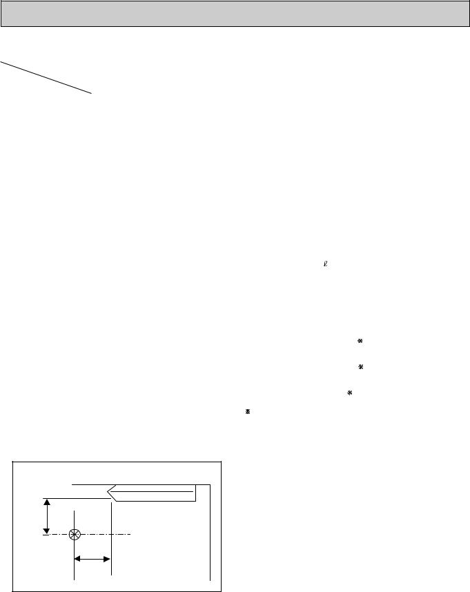
2-3. SOUND LEVEL |
|
PCFY-P•NKMU-E |
|
3.3ft |
|
(1m) |
|
Measurement |
3.3ft |
location |
(1m) |
* Measured in anechoic room.
|
Sound level at anechoic room : Low-Mid2-Mid1-High |
|
Service Ref. |
|
Sound level dB (A) |
PCFY-P15NKMU-E |
|
29-32-34-36 |
|
|
|
PCFY-P24NKMU-E |
|
31-33-35-37 |
|
|
|
PCFY-P30NKMU-E |
|
34-37-40-43 |
|
|
|
PCFY-P36NKMU-E |
|
36-39-42-44 |
|
|
|
5

2-4. NC CURVES |
|
|
|
|
|
|
|
|
|
|
|
|
|
|
|||
PCFY-P15NKMU-E |
|
|
|
|
|
PCFY-P24NKMU-E |
|
|
|
|
|||||||
External static pressure : 0Pa |
|
|
|
External static pressure : 0Pa |
|
|
|
||||||||||
Power source : 208V, 230V, 60Hz |
|
|
Power source : 208V, 230V, 60Hz |
|
|
||||||||||||
|
|
|
|
|
High |
|
Middle2 |
|
|
|
|
|
|
High |
|
Middle2 |
|
μPa |
70.0 |
|
|
|
Middle1 |
|
Low |
|
μPa |
70.0 |
|
|
|
Middle1 |
|
Low |
|
|
|
|
|
|
|
|
|
|
|
|
|
|
|
||||
65.0 |
|
|
|
|
|
|
|
65.0 |
|
|
|
|
|
|
|
||
0dB=20 |
|
|
|
|
|
|
NC-60 |
0dB=20 |
|
|
|
|
|
|
NC-60 |
||
60.0 |
|
|
|
|
|
|
60.0 |
|
|
|
|
|
|
||||
|
|
|
|
|
|
|
|
|
|
|
|
|
|
|
|
||
(dB) |
55.0 |
|
|
|
|
|
|
|
(dB) |
55.0 |
|
|
|
|
|
|
|
50.0 |
|
|
|
|
|
|
|
50.0 |
|
|
|
|
|
|
|
||
level |
45.0 |
|
|
|
|
|
|
NC-50 |
level |
45.0 |
|
|
|
|
|
|
NC-50 |
|
|
|
|
|
|
|
|
|
|
|
|
|
|
||||
|
|
|
|
|
|
|
|
|
|
|
|
|
|
|
|
||
pressure |
40.0 |
|
|
|
|
|
|
NC-40 |
pressure |
40.0 |
|
|
|
|
|
|
NC-40 |
35.0 |
|
|
|
|
|
|
35.0 |
|
|
|
|
|
|
||||
|
|
|
|
|
|
|
|
|
|
|
|
|
|
||||
|
|
|
|
|
|
|
|
|
|
|
|
|
|
|
|
||
band |
30.0 |
|
|
|
|
|
|
NC-30 |
band |
30.0 |
|
|
|
|
|
|
NC-30 |
25.0 |
|
|
|
|
|
|
25.0 |
|
|
|
|
|
|
||||
Octave |
15.0 |
|
|
|
|
|
|
NC-20 |
Octave |
15.0 |
|
|
|
|
|
|
NC-20 |
|
20.0 |
Approximate minimum |
|
|
|
|
|
|
20.0 |
Approximate minimum |
|
|
|
|
|
||
|
|
audible limit on |
|
|
|
|
|
|
|
|
audible limit on |
|
|
|
|
|
|
|
|
continuous noise |
|
|
|
|
|
|
|
|
continuous noise |
|
|
|
|
|
|
|
10.0 |
125 |
250 |
500 |
1k |
2k |
4k |
8k |
|
10.0 |
125 |
250 |
500 |
1k |
2k |
4k |
8k |
|
63 |
|
63 |
||||||||||||||
Octave band center frequencies (Hz) Octave band center frequencies (Hz)
PCFY-P30NKMU-E PCFY-P36NKMU-E
External static pressure : 0Pa |
|
|
|
External static pressure : 0Pa |
|
|
|
||||||||||
Power source : 208V, 230V, 60Hz |
|
|
Power source : 208V, 230V, 60Hz |
|
|
||||||||||||
|
|
|
|
|
High |
|
Middle2 |
|
0dB=20(dB)levelpressurebandOctaveμPa |
|
|
|
|
High |
|
Middle2 |
|
0dB=20(dB)levelpressurebandOctaveμPa |
70.0 |
|
|
|
Middle1 |
|
Low |
|
70.0 |
|
|
|
Middle1 |
|
Low |
|
|
|
|
|
|
|
|
|
|
|
|
|
|
|
|
||||
65.0 |
|
|
|
|
|
|
|
65.0 |
|
|
|
|
|
|
|
||
|
|
|
|
|
|
|
|
|
|
|
|
|
|
|
|
||
|
60.0 |
|
|
|
|
|
|
NC-60 |
|
60.0 |
|
|
|
|
|
|
NC-60 |
|
55.0 |
|
|
|
|
|
|
|
55.0 |
|
|
|
|
|
|
||
|
|
|
|
|
|
|
|
|
|
|
|
|
|
|
|
||
|
50.0 |
|
|
|
|
|
|
NC-50 |
|
50.0 |
|
|
|
|
|
|
NC-50 |
|
45.0 |
|
|
|
|
|
|
|
45.0 |
|
|
|
|
|
|
||
|
|
|
|
|
|
|
|
|
|
|
|
|
|
|
|
||
|
40.0 |
|
|
|
|
|
|
NC-40 |
|
40.0 |
|
|
|
|
|
|
NC-40 |
|
35.0 |
|
|
|
|
|
|
|
35.0 |
|
|
|
|
|
|
||
|
|
|
|
|
|
|
|
|
|
|
|
|
|
|
|
||
|
30.0 |
|
|
|
|
|
|
NC-30 |
|
30.0 |
|
|
|
|
|
|
NC-30 |
|
25.0 |
|
|
|
|
|
|
|
25.0 |
|
|
|
|
|
|
||
|
|
|
|
|
|
|
|
|
|
|
|
|
|
|
|
||
|
20.0 |
Approximate minimum |
|
|
|
|
|
|
20.0 |
Approximate minimum |
|
|
|
|
|
||
|
|
audible limit on |
|
|
|
|
|
NC-20 |
|
|
audible limit on |
|
|
|
|
|
|
|
15.0 |
continuous noise |
|
|
|
|
|
|
15.0 |
continuous noise |
|
|
|
|
|
NC-20 |
|
|
|
|
|
|
|
|
|
|
|
|
|
|
|
||||
|
10.0 |
125 |
250 |
500 |
1k |
2k |
4k |
8k |
|
10.0 |
125 |
250 |
500 |
1k |
2k |
4k |
8k |
|
63 |
|
63 |
||||||||||||||
Octave band center frequencies (Hz) |
Octave band center frequencies (Hz) |
6
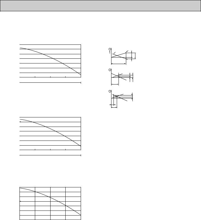
2-5. FRESH AIR INTAKE AMOUNT & STATIC PRESSURE CHARACTERISTICS
■ PCFY-P15NKMU-E
pressure[Pa(in.W.G.×10ˉ²] |
50(20) |
|
|
|
|
|
|
|
|
|
|
|
|
|
|
|
|
|
|
|
|
|
0 |
|
|
|
|
|
|
|
|
|
|
-50(-20) |
|
|
|
|
|
|
|
|
|
|
-100(-40) |
|
|
|
|
|
|
|
|
|
|
-150(-60) |
|
|
|
|
|
|
|
|
|
|
-200(-80) |
|
|
|
|
|
|
|
|
|
Static |
-250(-100) |
|
|
|
|
|
|
|
|
|
-300(-120) |
|
|
|
|
|
|
|
|
|
|
1 |
|
2 |
3 |
|||||||
|
|
|||||||||
|
0 |
|
||||||||
|
|
|
|
|
|
|
|
|
|
|
|
|
|
50 |
|
|
100 |
|
|||
|
|
|
|
|
|
Airflow rate |
|
|
|
|
■ PCFY-P24NKMU-E
pressure[Pa(in.W.G.×10ˉ²] |
50(20) |
|
|
|
|
|
|
|
|
|
|
|
|
|
|
|
|
|
|
|
|
|
0 |
|
|
|
|
|
|
|
|
|
|
-50(-20) |
|
|
|
|
|
|
|
|
|
|
-100(-40) |
|
|
|
|
|
|
|
|
|
|
-150(-60) |
|
|
|
|
|
|
|
|
|
|
-200(-80) |
|
|
|
|
|
|
|
|
|
Static |
-250(-100) |
|
|
|
|
|
|
|
|
|
-300(-120) |
|
|
|
|
|
|
|
|
|
|
1 |
|
2 |
3 |
|||||||
|
|
|||||||||
|
0 |
|
||||||||
|
|
|
|
|
|
|
|
|
|
|
|
|
|
50 |
|
|
100 |
|
|||
|
|
|
|
|
|
Airflow rate |
|
|
|
|
How to read curves
|
Curve in the |
Duct characteristics |
|
||
1 |
at site |
|
|
||
graphs |
Q…Designed amount of fresh air intake |
||||
|
|
||||
0 |
|
A C |
|||
|
|
<CMM(CFM)> |
|||
|
|
A…Static pressure |
|||
|
|
B |
loss of fresh air |
||
|
Q |
intake duct system with airflow |
|||
|
|
||||
|
|
|
amount Q |
<Pa(in.W.G.x10-2)> |
|
2 |
|
|
B…Forced static pressure at air con- |
||
|
|
ditioner inlet with airflow amount Q |
|||
|
|
C A |
|||
|
|
|
<Pa(in.W.G.x10-2)> |
||
|
|
|
|
||
4 [CMM] |
|
E |
C…Static pressure of booster fan with |
||
|
|
airflow amount Q <Pa(in.W.G.x10-2)> |
|||
[CFM] |
Q |
|
|||
|
|
|
D…Static pressure loss increase amount |
||
3 |
|
|
of fresh air intake duct system for |
||
|
D |
airflow amount Q <Pa(in.W.G.x10-2)> |
|||
|
|
E…Static pressure of indoor unit with |
|||
|
|
|
|||
|
|
A |
airflow amount Q <Pa(in.W.G.x10-2)> |
||
|
|
Qa…Estimated amount of fresh air |
|||
|
Q |
|
|||
|
|
intake without D |
<CMM(CFM)> |
||
|
Qa |
|
|||
|
|
|
|
||
4[CMM]
[CFM]
■ PCFY-P30, 36NKMU-E
Static pressure[Pa(in.W.G.×10ˉ²]
50(20)
0 -50(-20) -100(-40) -150(-60) -200(-80) -250(-100) -300(-120)
0 |
1 |
2 |
3 |
4 [CMM] |
|||||||||
|
|
|
|
|
|
|
|
|
|
|
|
|
[CFM] |
|
|
|
|
50 |
100 |
|
|
||||||
|
|
|
|
|
|
|
|
||||||
Airflow rate
7
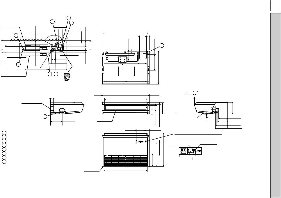
[FRONT VIEW]
|
|
|
|
|
|
5 |
1 |
|
|
|
Electrical box |
|
|
|
4 |
|
|
|
|||
|
|
|
|
|
|
|
||||
|
|
|
|
10-1/4(260) |
|
|
|
|||
1/2(190)-7 |
|
|
|
3(76) |
|
|
3-3/8(85) |
1/16(1) |
15/16(126)-4 |
|
|
3 |
Ceiling |
120° |
|
3-3/8(86) |
|
||||
|
|
|
|
|
|
|
|
|||
|
|
|
|
|
1/16(2) |
|
|
|
||
13/16(46)-1 |
3/4(121)-4 |
|
|
7/8(124)- |
15/16(Φ |
|
1-1/2(38) |
|
7/16(37)-1 |
-71/2(190) |
|
|
2-15/16(75) |
|
|
|
|
5-7/16(138) |
|
|
|
|
|
|
|
|
125) |
|
11/16(18) |
|
|
|
|
|
|
|
|
|
|
|
|
|
|
|
|
|
2 |
4 |
4 |
|
|
|
|
|
|
|
|
|
- |
|
|
|
|
|
|
|
|
|
|
|
Φ |
|
15-1/4(387) |
|
|
|
|
|
|
|
18-1/8(461) |
|
|
|
|
||
When electrical box |
|
|
8 |
|
7 |
|
|
|
||
is pulled down |
|
|
|
|
|
|
||||
In case of the rear pipe arrangement, make sure to 

 remove the shaded portions from the independent piece. Then put the independent piece back in initial
position.(The heat exchanger might be clogged because of dust)
36-1/16(917) (Suspension bolt pitch)
5-1/2(140)
5-7/8(150) |
11/16(18) |
2-7/16(62)
3-1/8(80) |
|
12-5/8(320) |
3/4(680) |
|
26- |
6
|
1/16(2) |
37-13/16(960) |
1/16(2) |
5/16(8) |
1-7/8(48) |
33-9/16(853) |
|
Electrical box |
|
|
|
|
|
8 |
|
|
|
|
1/16(230) |
|
|
|
|
|
9- |
2 |
When drain socket |
Air outlet |
5/16(84)-3 |
7/16(88)-3 |
11/16(195)- |
9-11/16(246) |
|||||
9-3/16(233) |
is installed |
|
|
|
|
|
Drainage |
|
|
|
7 |
|
|
7-3/16(182) |
3-3/8(85) |
|
|
1 Drainage pipe connection(1(26mm)I.D.)
2 Drainage pipe connection(for the left arrangement) 3 Knock out hole for left drain-piping arrangement
4 Refrigerant-pipe connection(gas pipe side/flared connection)
5 Refrigerant-pipe connection(liquid pipe side/flared connection)
6 Knock out hole for upper drain pipe arrangement 7 Knock out hole for fresh air intake Φ3-15/16(Φ100)
8Knock out hole for wiring arrangement Φ7/8(Φ22) Accessory...Drain socket (1(26mm) I.D.)
Air intake
|
3/4(476) |
2-1/4(57) |
26-3/4(680) |
10(254) |
18- |
|
|
34-9/16(878) |
|
|
|
E-P15NKMU-PCFY
2(51)
3/8(10)
3/16(5)
9/16 |
14 |
|
In case of wireless remote controller and i-see sensor (Optional Parts)
In case of wireless remote controller and i-see sensor(Optional Parts)
Emergency operation |
Emergency operation |
switch <Cooling> |
switch <Heating> |
9-5/16(236)
7-1/4(184) |
liquid Φ1/4(Φ6.35) |
8(203) |
gas Φ1/2(Φ12.7) |
9-3/16(233) |
When drain socket |
|
is installed |
9-11/16(246) |
Drainage |
|
|
|
NOTES. |
i-see sensor |
Receiver |
DEFROST/STAND BY lamp |
1.Use M10 or W3/8 screw for anchor bolt. |
|
|||
|
Operation lamp |
2.Please be sure when installing the |
|
|
|
|
drain lift up mechanism(option parts), |
|
|
|
refrigerant pipe will be only upward. |
|
|
|
inch(mm) : Unit |
DIMENSIONS AND OUTLINES 3
|
|
|
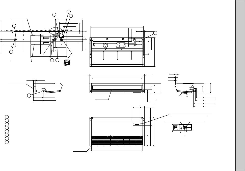
[FRONT VIEW] |
|
|
5 |
1 |
|
|
|
|
|
|
|
|
|
4 |
|
|
|
|||
|
Electrical box |
|
|
|
|
|
|
|
|||
|
|
|
|
|
10-1/4(260) |
|
|
|
|||
1/2(190)-7 |
|
|
3(76) |
Ceiling |
|
120° |
|
3-3/8(85) |
1/16(1) |
15/16(126)-4 |
|
|
3 |
|
|
1/16(2) |
|
||||||
|
|
|
|
|
|
|
3-3/8(86) |
|
|
|
|
13/16(46)-1 |
2 |
|
-47/8(124) |
3/4(121)-4 |
Φ4 |
|
|
5-7/16(138) |
|
7/16(37)-1 |
7-1/12(190) |
|
2-15/16(75) |
|
|
|
125) |
|
|
11/16(18) |
|
|
|
|
|
|
|
|
15/16(Φ |
|
|
1-1/2(38) |
|
|
|
|
|
|
|
|
|
|
|
|
|
|
|
|
|
|
|
|
- |
|
|
|
|
|
|
|
|
|
|
18-1/8(461) |
|
|
15-1/4(387) |
|
|
|
|
|
When electrical box |
|
|
8 |
|
7 |
|
|
|
||
|
is pulled down |
|
|
|
|
|
|
||||
In case of the rear pipe arrangement, make sure to 
 remove the shaded portions from the independent piece. Then put the independent piece back in initial
position.(The heat exchanger might be clogged because of dust)
1/16(2)
9 |
5/16(8) |
1-7/8(48) |
Electrical box |
|
|
|
|
2 |
|
When drain socket |
9-3/16(233) |
is installed |
|
|
9-11/16(246) |
Drainage |
1 Drainage pipe connection(1(26mm)I.D.)
2 Drainage pipe connection(for the left arrangement) 3 Knock out hole for left drain-piping arrangement
4 Refrigerant-pipe connection(gas pipe side/flared connection)
5 Refrigerant-pipe connection(liquid pipe side/flared connection)
6 Knock out hole for upper drain pipe arrangement 7 Knock out hole for fresh air intake Φ3-15/16(Φ100)
8Knock out hole for wiring arrangement Φ7/8(Φ22)
Accessory...Drain socket (1(26mm) I.D.)
Air intake
|
|
|
|
|
|
-PCFY |
7/8(150)-5 |
11/16(18) |
|
|
|
|
E-P24NKMU |
48-11/16(1237) (Suspension bolt pitch) |
|
|
|
|
|
|
|
|
5-1/2(140) |
2-7/16(62) |
6 |
|
|
|
|
|
|
|
|
|
|
|
|
12-5/8(320) |
3-1/8(80) |
3/4(680) |
|
|
|
|
|
|
26- |
|
Air outlet
50-3/8(1280) |
1/16(2) |
2(51) |
|
46-3/16(1173) |
3/8(10) |
|
|
|
3/16(5) |
|
|
|
9-1/16(230) |
|
|
|
9-5/16(236) |
|
5/16(84)-3 |
7/16(88)-3 |
11/16(195)-7 |
and i-see sensor |
9/16 |
14 |
9-3/16(233) |
|
|
|
|
In case of wireless |
|
|
7-1/16(180) |
|
|
|
|
|
|
7-7/8(200) |
|
|
|
|
|
remote controller |
|
|
|
|
|
|
|
|
|
|
|
7-3/16(182) |
3-3/8(85) |
|
(Optional Parts) |
|
|
9-11/16(246) |
|
|
|
|
|
||||
|
|
|
|
|
|
||
|
|
1/4(57)-2 |
|
and i-see sensor(Optional Parts) |
|
||
|
|
|
|
In case of wireless remote controller |
|||
liquid Φ3/8(Φ9.52)
gas Φ5/8(Φ15.88)
When drain socket is installed
Drainage
|
3/4(476) |
26-3/4(680) |
10(254) |
18- |
|
47-3/16(1198)
Emergency operation |
Emergency operation |
|
switch <Cooling> |
|
switch <Heating> |
i-see sensor |
Receiver |
DEFROST/STAND BY lamp |
|
Operation lamp |
|
NOTES.
1.Use M10 or W3/8 screw for anchor bolt. 2.Please be sure when installing the drain lift up
mechanism(option parts),refrigerant pipe will be only upward. Unit:
inch(mm)

|
|
[FRONT VIEW] |
|
|
|
|
5 |
1 |
|
|
|
|
|
|
|
|
4 |
|
|
||
|
|
|
|
|
|
|
|
|
|
|
|
|
|
|
|
|
|
|
10-1/4(260) |
|
|
1/2(190)-7 |
|
3(76) |
|
|
|
|
|
3-3/8(85) |
1/16(1) |
15/16(126)-4 |
3 |
|
|
|
|
|
3-3/8(86) |
||||
|
Electrical box |
|
|
|
|
|
|
|
||
|
|
|
2 |
0 |
° |
|
1/16(2) |
|
|
|
|
|
Ceiling |
1 |
|
|
|
|
|
||
|
|
|
|
|
|
|
|
|
1-13/16(46)
2-15/16(75)
2When electrical box is pulled down
4-7/8(124)
|
) |
|
5 |
3/4(121)-4 |
2 |
- |
|
|
1 |
|
(Φ |
|
6 |
|
/1 |
|
5 |
|
1 |
|
4 |
|
Φ |
18-1/8(461)
11/16(18)
1-1/2(38)
15-1/4(387)
8 7
5-7/16(138)
1-7/16(37) |
7-1/2(190) |
In case of the rear pipe arrangement, make sure to 
 remove the shaded portions from the independent piece. Then put the independent piece back in initial
position.(The heat exchanger might be clogged because of dust)
5/16(8) 1-7/8(48) 1/16(2)
Electrical box
10 |
2 |
|
When drain socket
9-3/16(233) is installed
9-11/16(246) Drainage
1 |
Drainage pipe connection(1(26mm)I.D.) |
2 |
Drainage pipe connection(for the left arrangement) |
3 |
Knock out hole for left drain-piping arrangement |
4 |
Refrigerant-pipe connection |
|
(gas pipe side/flared connection) |
5Refrigerant-pipe connection (liquid pipe side/flared connection)
6 Knock out hole for upper drain pipe arrangement 7 Knock out hole for fresh air intake Φ3-15/16(Φ100)
8Knock out hole for wiring arrangement Φ7/8(Φ22) Accessory...Drain socket (1(26mm)I.D.)
NOTES.
1.Use M10 or W3/8 screw for anchor bolt. 2.Please be sure when installing the drain lift up
mechanism (option parts),refrigerant pipe will be only upward.
61-5/16(1557) (Suspension bolt pitch)
7/8(150)-5 |
11/16(18) |
5-1/2 |
|
140 |
|||
|
|
63(1600)
58-3/4(1493)
Air outlet
7-3/16
182
59-3/4(1518)
6
62 |
|
2-7/16 |
|
1/8 |
80 |
3- |
|
12-5/8(320) |
26-3/4(680) |
|
2(51) |
1/16(2) |
3/8(10) |
|
3/16(5) |
|
|
|
9-1/16(230) |
|
5/16(84)-3 |
7/16(88)-3 |
11/16(195)- |
9/16 |
14 |
remote controller |
|
|||
|
|
|
In case of wireless |
|
|
|
7 |
and i-see sensor |
|
|
|
|
|
|
3-3/8 |
|
(Optional Parts) |
|
|
85 |
|
|
|
|
E-36NKMU P30,-PCFY
9-5/16(236) |
|
7-1/16(180) |
liquid Φ3/8(Φ9.52) |
7-7/8(200) gas Φ5/8(Φ15.88)
9-3/16(233) When drain socket is installed
9-11/16(246) Drainage
|
2-1/4 |
57 |
In case of wireless remote controller |
|
|
|
|
||
10(254) |
3/4(476)-18 |
3/4(680)-26 |
and i-see sensor(Optional Parts) |
|
Emergency operation |
Emergency operation |
|||
|
|
|
switch <Cooling> |
switch <Heating> |
Receiver |
DEFROST/STAND BY lamp |
|
|
Operation lamp |
|
Air intake |
|
inch(mm) : Unit
4 
 WIRING DIAGRAM
PCFY-P15, 24, 30, 36NKMU-E
[LEGEND] |
|
|
|
|
|
|
|
|
LED on indoor board for service |
|||||
|
SYMBOL |
|
NAME |
SYMBOL |
|
|
NAME |
|
Mark |
Meaning |
Function |
|||
|
I. B |
INDOOR CONTROLLER BOARD |
TH22 |
THERMISTOR |
|
PIPE TEMP. DETECTION / LIQUID |
|
LED1 |
Main power supply |
Main Power supply (Indoor unit:208-230V) |
||||
|
|
CN24 |
CONNECTOR |
EXTERNAL HEATER |
|
|
|
|
|
(32°F/15ΚΩ, 77°F/5.4ΚΩ Detect) |
|
power on → lamp is lit |
||
|
|
CN27 |
|
DAMPER |
TH23 |
|
|
PIPE TEMP. DETECTION / GAS |
|
LED2 |
Power supply for |
Power supply for MA-Remote controller |
||
|
|
CN32 |
|
REMOTE SWITCH |
|
|
|
|
|
(32°F/15ΚΩ, 77°F/5.4ΚΩ Detect) |
|
MA-Remote controller |
on → lamp is lit |
|
|
|
|
|
|
|
|
|
|
|
|
|
|
|
|
|
|
CN51 |
|
CENTRALLY CONTROL |
A. B |
ADDRESS BOARD |
|
|
|
|
||||
|
|
CN52 |
|
REMOTE INDICATION |
|
SWA |
SWITCH |
|
CEILING HEIGHT SELECTOR |
|
|
|
|
|
|
|
DSA |
SURGE ABSORBER |
|
SWC |
|
|
OPTION SELECTOR |
|
|
|
|
||
|
|
FUSE |
FUSE (T6.3AL250V) |
|
SW1 |
|
|
MODE SELECTION |
|
|
|
|
||
|
|
SW2 |
SWITCH |
CAPACITY CODE |
|
SW11 |
|
|
ADDRESS SETTING 1s DIGIT |
|
|
|
|
|
|
|
SW3 |
|
MODE SELECTION |
|
SW12 |
|
|
ADDRESS SETTING 10ths DIGIT |
|
|
|
|
|
|
|
SW4 |
|
MODEL SELECTION |
|
SW14 |
|
|
BRANCH No. |
|
|
|
|
|
|
|
SWE |
|
DRAIN LIFT UP MECHANISM (TEST MODE) |
OPTIONAL PARTS |
|
|
|
|
|
|
|
||
|
|
X1 |
AUX. RELAY |
DRAIN LIFT UP MECHANISM (OPTIONAL PARTS) |
|
W.B |
PCB FOR WIRELESS REMOTE CONTROLLER |
|
|
|
|
|||
|
|
ZNR01,02 |
VARISTOR |
|
|
|
BZ |
BUZZER |
|
|
|
|
|
|
|
LEV |
LINEAR EXPANSION VALVE |
|
|
LED1 |
LED (OPERATION INDICATION : GREEN) |
|
|
|
|
||||
|
MF |
FAN MOTOR |
|
|
|
LED2 |
LED (PREPARATION FOR HEATING : ORANGE) |
|
|
|
|
|||
|
MV |
VANE MOTOR |
|
|
|
RU |
RECEVING UNIT |
|
|
|
|
|
||
|
MT |
I-SEE SENSOR MOTOR(OPTIONAL PARTS) |
|
|
SW1 |
EMERGENCY OPERATION (HEAT / DOWN) |
|
|
|
|
||||
|
TB2 |
TERMINAL |
POWER SUPPLY |
|
|
SW2 |
EMERGENCY OPERATION (COOL / UP) |
|
|
|
|
|||
|
TB5 |
BLOCK |
TRANSMISSION |
|
DP |
DRAIN LIFT UP MECHANISM |
|
|
|
|
||||
|
TB15 |
|
MA-REMOTE CONTROLLER |
|
|
FS |
DRAIN FLOAT SWITCH |
|
|
|
|
|||
|
TH21 |
THERMISTOR |
ROOM TEMP. DETECTION |
|
|
|
|
|
|
|
|
|
|
|
|
|
|
|
(32°F/15ΚΩ, 77°F/5.4ΚΩ Detect) |
|
|
|
|
|
|
|
|
|
|
|
A.B |
|
|
|
|
|
|
|
(RED) 4 |
|
<Fig. w1> |
|
|
|
|
|
|
|
|
|
|
|
|
|
|
|
|
|
|
|
|
POWER SUPPLY |
||
|
|
|
|
|
|
|
|
|
MODELS |
|
SW2 |
|
|
|
|
|
SW3 |
|
|
|
|
|
|
|
|
|
||||||||
|
|
|
|
|
|
|
|
ADDRESS |
|
|
ON |
|
|
|
|
|
ON |
|
|
|
|
|
|
|
|
|
BLU |
TB5 |
TO OUTDOOR UNIT |
|
~208-230V 60Hz |
|||
|
|
|
|
|
|
|
|
|
CN43 |
|
P15 |
|
|
|
|
|
|
|
|
|
|
|
|
|
|
|
M1 |
|
|
|||||
|
|
|
|
|
|
|
|
SWA |
|
OFF |
2 |
3 |
4 |
5 |
6 |
OFF |
2 |
3 |
4 |
5 |
6 |
7 |
8 |
9 |
10 |
BLU |
BC CONTROLLER |
|
BREAKER |
|||||
|
SW1 |
|
|
|
|
|
|
1 |
8 |
|
1 |
1 |
M2 |
|
||||||||||||||||||||
|
|
|
|
3 |
|
|
|
|
|
|
|
|
|
|
|
|
|
|
|
|
|
|
|
|
|
|
S |
REMOTE CONTROLLER |
|
(16A) |
||||
|
ON |
|
|
|
|
|
|
|
|
|
|
|
ON |
|
|
|
|
|
|
|
|
|
|
|
|
|
|
|
|
DC24-30V |
|
|||
MV |
|
|
|
|
|
2 |
|
|
|
|
|
P24 |
|
|
|
|
|
|
|
|
|
|
|
|
|
|
|
|
|
|
||||
OFF |
|
|
|
|
|
|
|
|
|
|
(RED) |
OFF |
2 |
3 |
4 |
5 |
6 |
|
|
|
|
|
|
|
|
|
|
|
(SHIELD) |
|
|
|
||
M |
12345678910 1 |
|
|
|
|
|
1 |
|
|
|
|
|
|
|
|
|
|
|
<w2> |
FUSE(16A) |
||||||||||||||
SW12 |
SW11 |
|
SW14 ADDRESS |
|
ON |
|
|
|
|
|
|
|
|
|
|
|
|
|
|
|
|
|
||||||||||||
|
9 |
0 |
1 |
9 |
0 |
1 |
|
SWC |
EF |
0123 |
CN82 |
P30 |
|
|
|
|
|
ON |
|
|
|
|
|
|
|
|
|
|
|
RED |
TB2 |
|
||
|
8 |
|
2 |
8 |
|
|
2 |
2 |
CD |
|
4 |
|
OFF |
|
|
|
|
|
OFF |
|
|
|
|
|
|
|
|
|
|
|
|
PULL BOX |
||
|
7 |
|
3 |
7 |
|
|
3 |
B |
876 |
5 |
|
|
1 |
2 |
3 |
4 |
5 |
6 |
1 |
2 |
3 |
4 |
5 |
6 |
7 |
8 |
9 |
10 |
|
|
BLU L1 |
|||
|
6 |
5 |
4 |
6 |
5 |
4 |
1 |
A9 |
|
|
|
|
|
|
||||||||||||||||||||
5 |
10ths |
1s |
|
BRANCH |
1 |
P36 |
ON |
|
|
|
|
|
|
|
|
|
|
|
|
|
|
|
|
|
GRN/YLW |
L2 |
TO NEXT |
|||||||
DIGIT |
DIGIT |
No. |
OFF |
2 |
3 |
4 |
5 |
6 |
|
|
|
|
|
|
|
|
|
|
|
|
|
GR |
||||||||||||
|
|
|
|
|
|
|
|
|
|
|
|
|
|
1 |
|
|
|
|
|
|
|
|
|
|
|
|
|
|
INDOOR UNIT |
|||||
45
I-SEE M
SENSOR
MT
I-SEE SENSOR (OPTIONAL PARTS)
20 18 16 14 12 10 |
8 |
6 |
4 |
2 |
||
19 17 15 13 11 |
9 |
|
7 |
5 |
3 |
1 |
I-SEE SENSOR MOTOR |
|
VANE CNV |
||||
|
|
(WHT) |
|
|||
CN6Y |
|
|
|
|
|
|
1 (RED) 6 |
|
|
MA REMOCON |
|||
|
|
|
||||
|
|
|
|
|
CN3A |
|
|
|
|
|
|
(BLU) |
|
I-SEE SENSOR |
|
|
|
|
1 |
3 |
CN4Y |
|
|
|
|
|
|
1 (WHT) 4 |
|
|
LEV |
|
|
|
1 |
|
CN60 |
6 |
|
||
|
(WHT) |
|
||||
CN52 |
5 |
|
|
1 |
CN51 |
|
1 (GRN) |
|
|
(WHT) 5 |
|||
|
|
|
|
6 |
|
|
WHT YLW |
ORN |
BLU |
RED |
BRN |
|
|
M
LEV
|
|
8 |
|
|
|
4 |
|
See fig.w1 |
|
|
|
|
|
|
|
I.B |
|
CN32 |
J42 J41 |
|
|
|
|
SW3 |
SW4 |
SW2 |
|
|
|
|
|
|
1 3 |
5 |
|
(WHT) |
|
|
|
|
ON |
|
|
ON |
|
|
2 |
1 |
|
|
|
CND |
|
|
|
|
|
|
|
|
|
|
|
|
|
|
(BLK) |
||||
1 |
3 |
|
|
|
|
OFF |
|
|
OFF |
|
|
M-NET |
|
|
|
|
|
1 |
|
8 |
1 |
4 |
12345678910 |
12345 |
123456 |
|
|
|
DSA |
|
|||||
ADDRESS |
|
|
CN2M |
|
|
||||||||||||
|
|
Pair No. |
|
ADDRESS |
|
|
|
|
|
|
|
|
|
||||
|
|
|
CN81 |
|
|
CN42 |
SWE |
|
|
|
|
(BLU) |
|
|
|
|
|
|
|
|
|
|
|
|
|
|
|
|
|
ZNR02 |
|
|
|||
|
|
|
(RED) |
|
|
(RED) |
|
|
|
|
|
DC294~325V |
|
U |
|
||
LED2 |
|
|
|
|
|
|
OFF ON |
|
|
|
|
RECTIFICATION |
FUSE |
|
|||
|
|
|
|
|
|
|
|
|
|
|
|
|
|
|
|
|
|
|
|
|
WIRELESS |
|
|
|
|
|
|
|
|
|
|
ZNR01 U |
|
|
|
|
|
|
CN90 |
|
|
|
|
|
|
|
|
|
|
|
|
|
|
|
|
1 |
(WHT) |
|
9 |
|
|
|
CN24 |
CN25 |
|
|
|
|
|
||
|
|
|
|
|
|
|
|
|
(YLW) |
(WHT) |
|
|
|
|
|
||
|
|
|
|
|
|
|
|
|
1 |
2 |
1 |
2 |
|
|
|
|
|
|
|
|
|
|
|
|
|
|
|
|
|
|
LED1 |
|
|
|
|
|
|
|
|
|
|
LIQUID/PIPE |
FLOAT SW |
|
|
|
INTAKE |
CN27 |
|
FAN |
|
X1 |
|
CN41 |
|
|
|
|
|
|
|
CN20 |
|
CNMF |
|
|
|||||
|
|
|
|
CN44 |
CN4F |
|
|
|
(RED) |
(RED) |
|
(WHT) |
|
D.U.MCNP 3 1 |
|||
1 (WHT) 4 |
|
9 |
|
|
1 (WHT) 4 |
1 (WHT) 4 |
|
|
|
1 |
2 |
1 2 |
7 |
4 |
1 |
||
|
|
|
|
|
|
|
|
|
|
|
|
|
|
|
|
(BLU) |
|
BLU |
TB15 |
TO MA-REMOTE |
CNB |
BZ |
|
|
|
When attaching |
|
|
M |
|
1 |
|
|
|
|
MS |
|||||||
BLU |
2 |
CONTROLLER |
|
|
|
|
When attaching |
drain lift up |
|
|
1~ |
|
|
|
DC8.7-13V |
SW1 |
LED2 |
|
|
drain lift up |
mechanism |
|
|
3~ |
DP |
|
|
|
t° |
t° |
mechanism |
(optional parts) |
t° |
MF |
(OPTIONAL PARTS) |
|||
|
|
|
|
|
||||||||
|
|
|
|
LED1 |
|
|
(optional parts), |
1 |
|
4 |
wBe sure to turn off the source power |
|
|
|
|
SW2 |
|
|
remove the jumper |
FLOAT SW |
|
|
|||
|
|
|
RU |
|
|
|
connector CN4F |
CN4F |
|
|
and then disconnect fan motor connector. |
|
|
|
W.B |
|
TH22 |
TH23 |
(WHT) |
FS |
TH21 |
(Failure to do so will cause trouble in Fan motor) |
|||
|
|
|
|
and fit the drain |
||||||||
|
|
|
(OPTIONAL PARTS) |
|
|
float switch (FS). |
|
|
|
|
|
|
NOTES:
1.At servicing for outdoor unit, always follow the wiring diagram of outdoor unit.
2.In case of using MA-Remote controller, please connect to TB15. (Remote controller wire is non-polar.) 3.In case of using M-NET, please connect to TB5. (Transmission line is non-polar.)
4.Symbol [S] of TB5 is the shield wire connection.
5.Symbols used in wiring diagram above are, 


 : terminal block,
  : connecter. 6.The setting of the SW2 dip switches differs in the capacity. For the detail, refer to fig.w1.
<w2>Use copper supply wires.
11
 Loading...