


Grandis 2003 2011
Table of contents
 Loading...
80-1
GROUP 80
CONFIGURATION
DIAGRAMS
CONTENTS
OVERALL CONFIGURATION DIAGRAM
. . . . . . . . . . . . . . . . . . . . . . . . . . . . . . . . . 80-2
OVERALL WIRING DIAGRAM <LHD> . . . . 80-2
OVERALL WIRING DIAGRAM <RHD> . . . 80-3
ENGINE COMPARTMENT. . . . . . . . . 80-4
ENGINE COMPARTMENT <LHD>. . . . . . . 80-4
ENGINE COMPARTMENT <RHD> . . . . . . 80-5
ENGINE AND TRANSMISSION. . . . . 80-6
ENGINE AND TRANSMISSION <LHD> . . . 80-6
ENGINE AND TRANSMISSION <RHD> . . 80-7
DASH PANEL . . . . . . . . . . . . . . . . . . 80-9
DASH PANEL <LHD> . . . . . . . . . . . . . . . . . 80-9
DASH PANEL <RHD> . . . . . . . . . . . . . . . . . 80-13
FLOOR . . . . . . . . . . . . . . . . . . . . . . . . 80-17
FLOOR <LHD> . . . . . . . . . . . . . . . . . . . . . . 80-17
FLOOR <RHD> . . . . . . . . . . . . . . . . . . . . . . 80-18
ROOF . . . . . . . . . . . . . . . . . . . . . . . . . 80-19
ROOF <LHD> . . . . . . . . . . . . . . . . . . . . . . . 80-19
ROOF < RHD > . . . . . . . . . . . . . . . . . . . . . . 80-19
DOOR . . . . . . . . . . . . . . . . . . . . . . . . . 80-20
DOOR <LHD> . . . . . . . . . . . . . . . . . . . . . . . 80-20
DOOR <RHD> . . . . . . . . . . . . . . . . . . . . . . . 80-21
TAILGATE . . . . . . . . . . . . . . . . . . . . . 80-22
OVERALL CONFIGURATION DIAGRAM
CONFIGURATION DIAGRAMS
80-2
OVERALL CONFIGURATION DIAGRAM
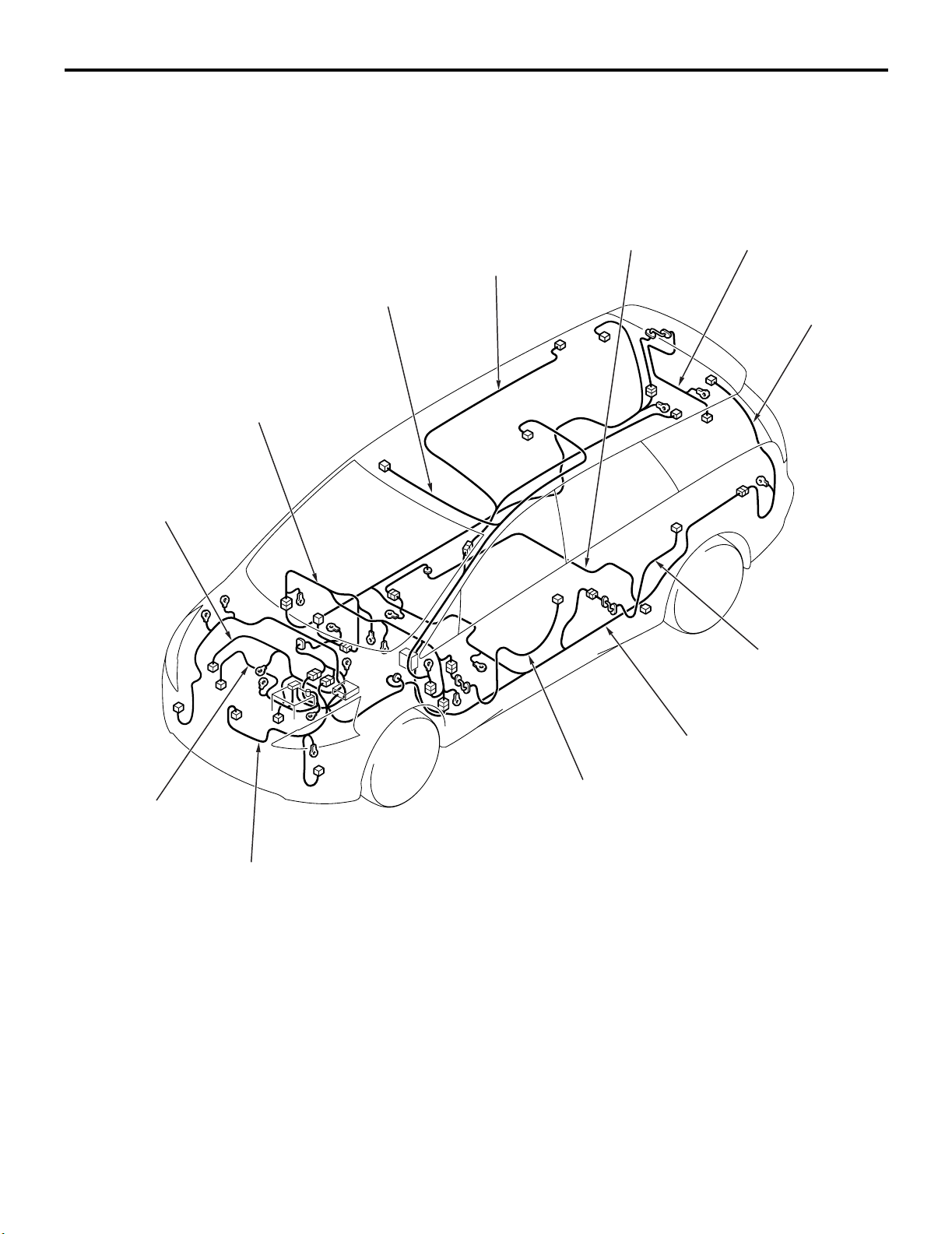
OVERALL WIRING DIAGRAM <LHD>
M1801000100699
NOTE: .
1. This illustration shows only major wiring harnesses.
2. *: also equipped at the right side.
AC310351
AB
*
Control wiring
harness
Instrument panel
wiring harness
Roof wiring
harness
Floor wiring
harness
Battery wiring
harness
Front wiring
harness
Front door
wiring harness
Rear floor
wiring harness
Fuel wiring
harness
Rear door
wiring harness
*
Tailgate wiring
harness
Room lamp
wiring harness
OVERALL CONFIGURATION DIAGRAM
CONFIGURATION DIAGRAMS
80-3
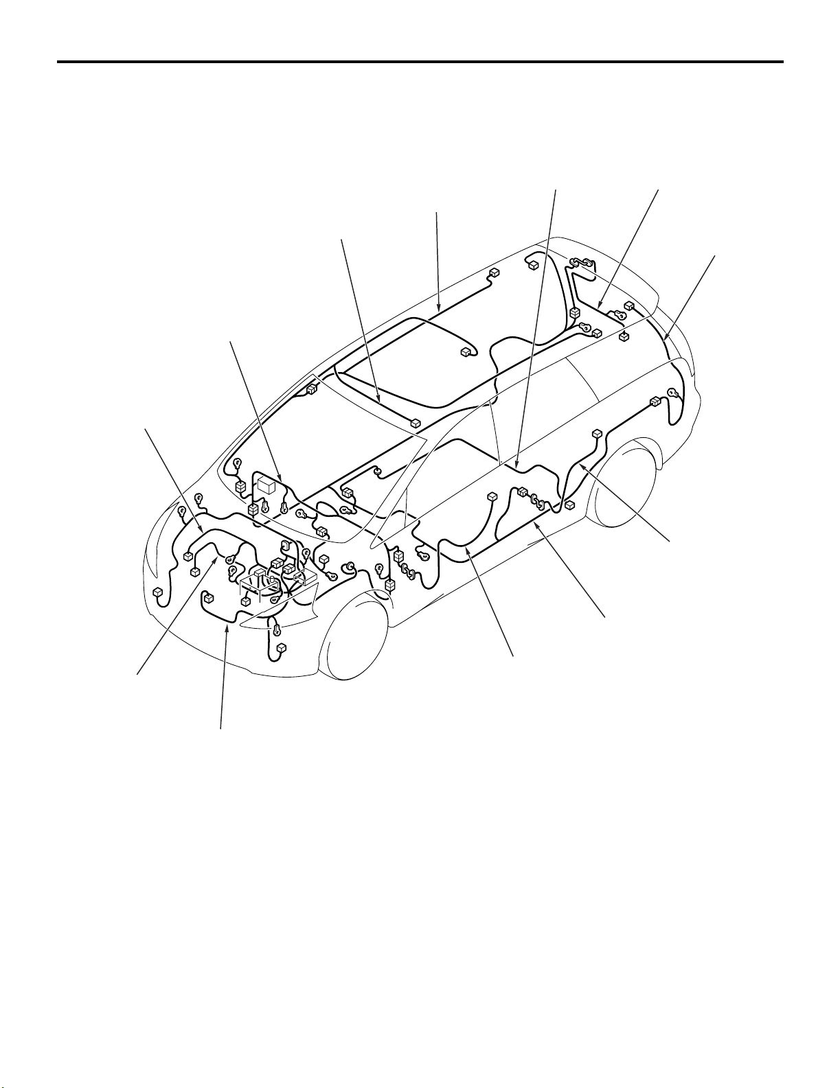
OVERALL WIRING DIAGRAM <RHD>
M1801000100707
NOTE: .
1. This illustration shows only major wiring harnesses.
2. *: also equipped at the right side.
AC310352
AB
*
Control wiring
harness
Instrument panel
wiring harness
Roof wiring
harness
Floor wiring
harness
Battery wiring
harness
Front wiring
harness
Front door
wiring harness
Rear floor
wiring harness
Fuel wiring
harness
Rear door
wiring harness
*
Tailgate wiring
harness
Room lamp
wiring harness
ENGINE COMPARTMENT
CONFIGURATION DIAGRAMS
80-4
ENGINE COMPARTMENT
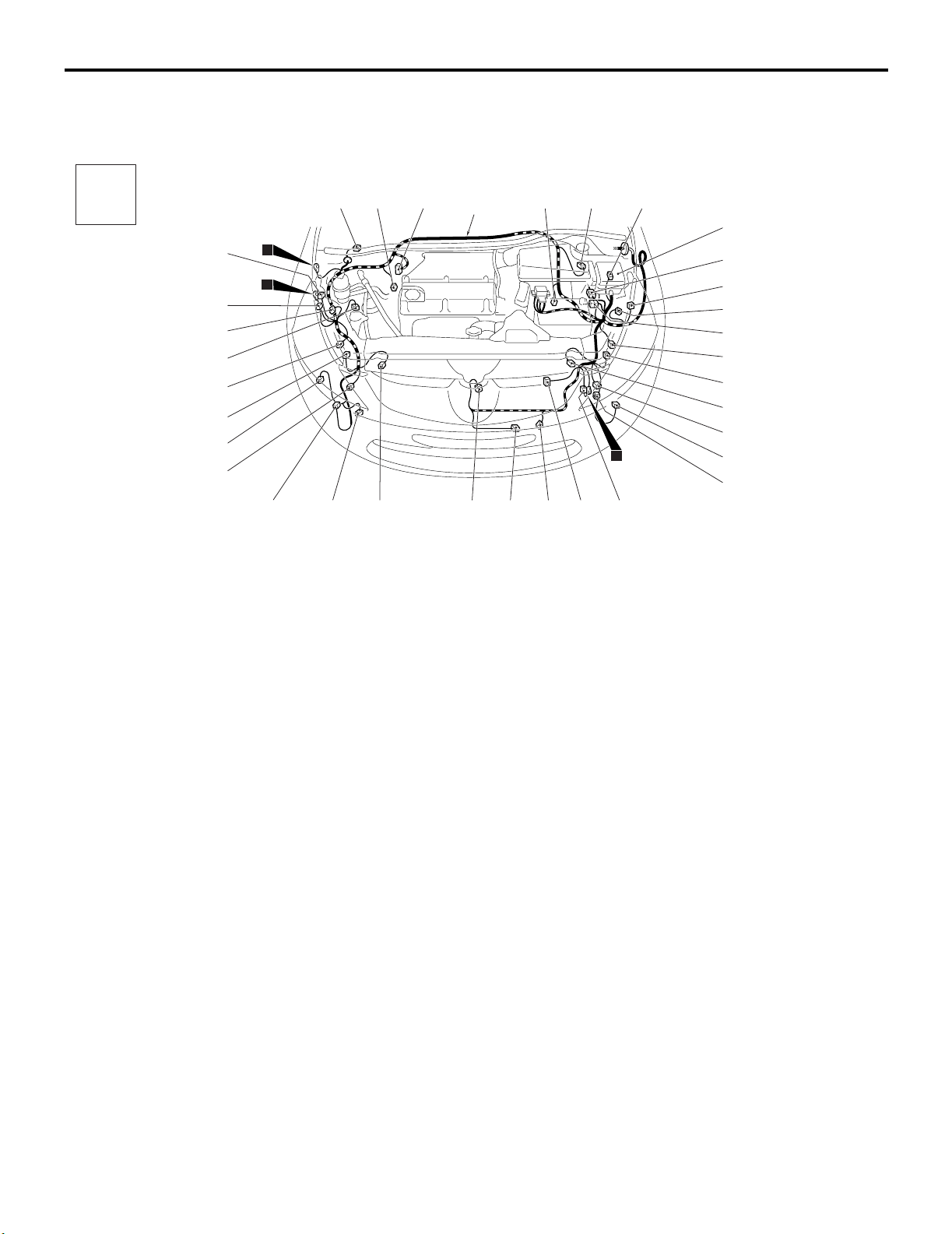
ENGINE COMPARTMENT <LHD>
M1801000301113
AC310245
Connector
symbol
A
AB
A-40
2
1
A-38
A-39
A-01
A-02
A-03
A-04
A-37
A-35
A-36
A-34
A-32
A-33
A-31
A-30
Connector colour code
B : Black
BR : Brown
G : Green
GR : Gray
L : Blue
None : Milk white
O : Orange
R : Red
V : Violet
Y : Yellow
A-07
A-18
A-17
A-05
A-06
A-08X A-09X
A-13X A-14X
A-15X
A-16
A-19
A-21
A-20
A-22
A-23
A-24
A-26
A-25
A-28
A-27
A-29
11
Front wiring
harness
A-41
A-01 (5-GR) Windshield wiper motor
A-02 (2-GR) Wheel speed sensor (Front: RH)
A-03 (26) ABS-ECU <Vehicles without ASC>
A-04 (47) ASC-ECU <Vehicles with ASC>
A-05 (2-GR) Wheel speed sensor (Front: LH)
A-06 (2-GR) Brake fluid level indicator switch
A-07 (6) J/C (CAN 1)
A-08X (4) Front fog lamp relay
A-09X (4) Horn relay
A-13X (4) Fan control relay
A-14X (11) Front-ECU
A-15X (11) Front-ECU
A-16 (12-B) Front wiring harness and control
wiring harness combination
A-17 (2-GR) Position lamp (LH)
A-18 (2-B) Headlamp (LO: LH)
A-19 (4-B) Front wiring harness and battery
wiring harness combination
A-20 (3-GR) Headlamp leveling unit (LH)
A-21 (2-GR) Headlamp (HI: LH)
A-22 (2-Y) Front impact sensor (LH)
A-23 (2-B) Front turn-signal lamp (LH)
A-24 (2-B) Front fog lamp (LH)
A-25 (6-GR) Earth
A-26 (3-GR) Fan controller
A-27 (1-B) Horn (LO)
A-28 (2-B) Ambient temperature sensor
A-29 (1-B) Horn (HI)
A-30 (2-Y) Front impact sensor (RH)
A-31 (2-GR) Headlamp washer motor
A-32 (2-B) Front fog lamp (RH)
A-33 (2-B) Front turn-signal lamp (RH)
A-34 (2-GR) Washer motor
A-35 (2-GR) Headlamp (HI: RH)
A-36 (3-GR) Headlamp leveling unit (RH)
A-37 (3-B) A/C pressure sensor
A-38 (2-B) Headlamp (LO: RH)
A-39 (2-GR) Position lamp (RH)
A-40 (6-GR) Earth
A-41 (4-B) Spare connector (For trailer)
ENGINE COMPARTMENT
CONFIGURATION DIAGRAMS
80-5
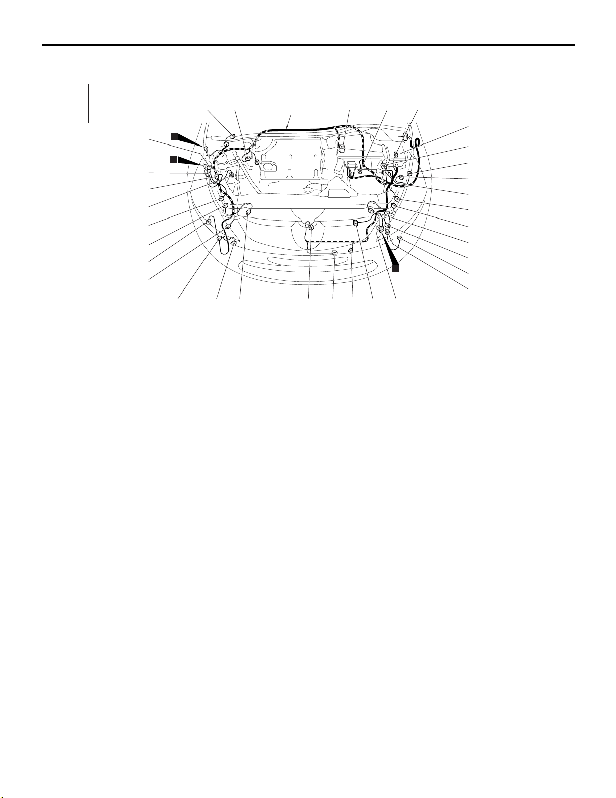
ENGINE COMPARTMENT <RHD>
M1801000301124
AC310248
Connector
symbol
A
AB
A-40
2
1
A-38
A-39
A-01
A-02
A-06
A-37
A-35
A-36
A-34
A-32
A-33
A-31
A-30
Connector colour code
B : Black
BR : Brown
G : Green
GR : Gray
L : Blue
None : Milk white
O : Orange
R : Red
V : Violet
Y : Yellow
A-07
A-18
A-17
A-03
A-04
A-05
A-08X A-09X
A-13X A-14X
A-15X
A-16
A-19
A-21
A-20
A-22
A-23
A-24
A-26
A-25
A-28
A-27
A-29
11
Front wiring
harness
A-41
A-01 (5-GR) Windshield wiper motor
A-02 (2-GR) Wheel speed sensor (Front: RH)
A-03 (26) ABS-ECU <Vehicles without ASC>
A-04 (47) ASC-ECU <Vehicles with ASC>
A-05 (2-GR) Wheel speed sensor (Front: LH)
A-06 (2-GR) Brake fluid level indicator switch
A-07 (6) J/C (CAN 1)
A-08X (4) Front fog lamp relay
A-09X (4) Horn relay
A-13X (4) Fan control relay
A-14X (11) Front-ECU
A-15X (11) Front-ECU
A-16 (12-B) Front wiring harness and control
wiring harness combination
A-17 (2-GR) Position lamp (LH)
A-18 (2-B) Headlamp (LO: LH)
A-19 (4-B) Front wiring harness and battery
wiring harness combination
A-20 (3-GR) Headlamp leveling unit (LH)
A-21 (2-GR) Headlamp (HI: LH)
A-22 (2-Y) Front impact sensor (LH)
A-23 (2-B) Front turn-signal lamp (LH)
A-24 (2-B) Front fog lamp (LH)
A-25 (6-GR) Earth
A-26 (3-GR) Fan controller
A-27 (1-B) Horn (LO)
A-28 (2-B) Ambient temperature sensor
A-29 (1-B) Horn (HI)
A-30 (2-Y) Front impact sensor (RH)
A-31 (2-GR) Headlamp washer motor
A-32 (2-B) Front fog lamp (RH)
A-33 (2-B) Front turn-signal lamp (RH)
A-34 (2-GR) Washer motor
A-35 (2-GR) Headlamp (HI: RH)
A-36 (3-GR) Headlamp leveling unit (RH)
A-37 (3-B) A/C pressure sensor
A-38 (2-B) Headlamp (LO: RH)
A-39 (2-GR) Position lamp (RH)
A-40 (6-GR) Earth
A-41 (4-B) Spare connector (For trailer)
ENGINE AND TRANSMISSION
CONFIGURATION DIAGRAMS
80-6
ENGINE AND TRANSMISSION
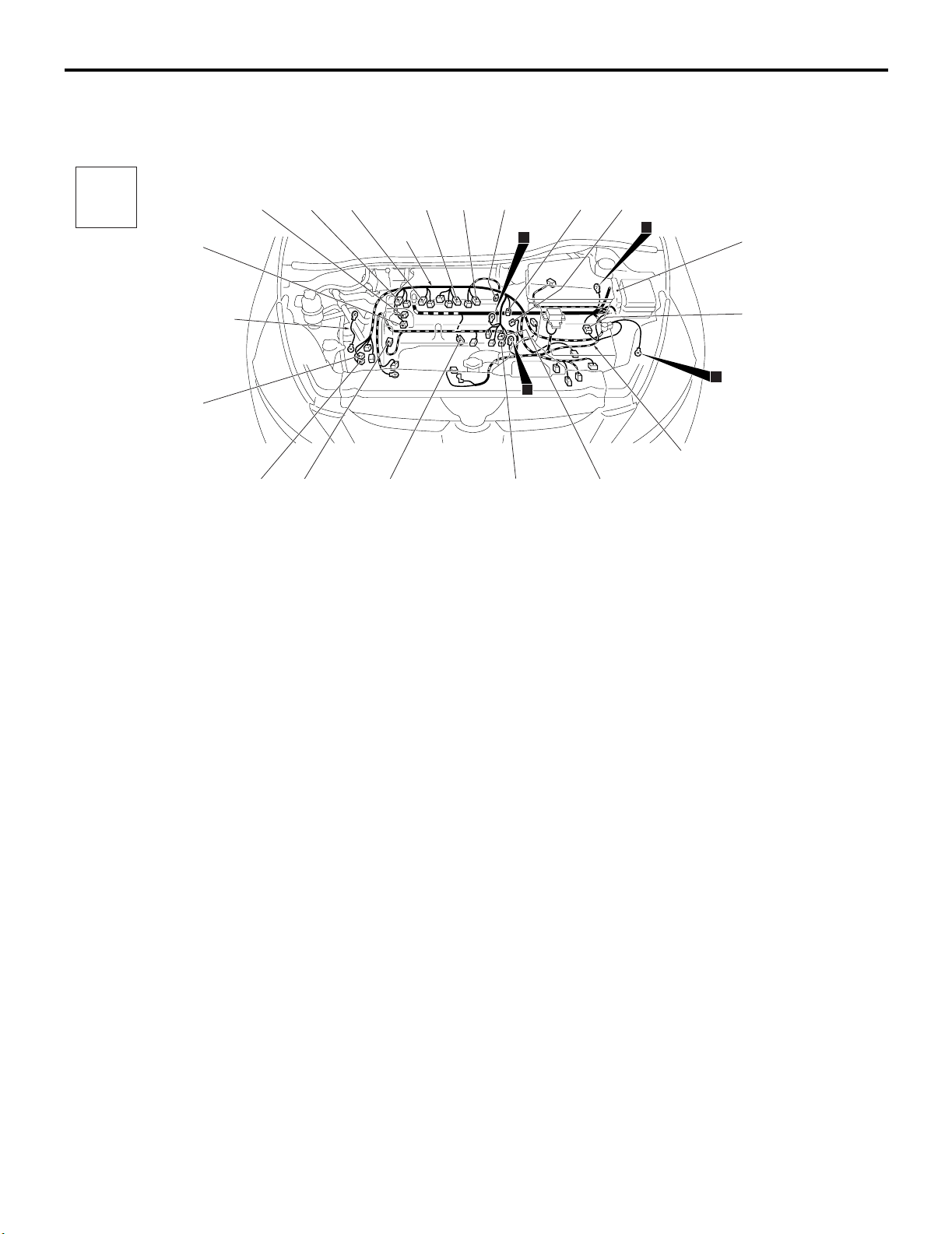
ENGINE AND TRANSMISSION <LHD>
M1801000400935
AC310306
Connector
symbol
-01
thru
-24
B
AB
B-01
B-24
B-02
B-23
B-20B-21
B-22
B-03
B-04
B-05
Control wiring
harness
Earth cable
B-06
3
9
10
12
B-07
B-08
B-12X B-14X
B-15X B-16X
B-17
B-18
B-19
Battery wiring
harness
Connector colour code
B : Black
BR : Brown
G : Green
GR : Gray
L : Blue
None : Milk white
O : Orange
R : Red
V : Violet
Y : Yellow
B-01 (2-B) Purge control solenoid valve
B-02 (3-GR) Ignition coil 1
B-03 (3-GR) Ignition coil 2
B-04 (3-GR) Ignition coil 3
B-05 (3-GR) Ignition coil 4
B-06 (6-B) Electronic-controlled throttle valve
B-07 (2-B) Engine oil control valve
B-08 (2-B) Engine coolant temperature sensor
B-12X (4) Throttle valve control servo relay
B-14X (4) A/T control relay
B-15X (4) Engine control relay
B-16X (4) A/C compressor relay
B-17 (8-B) Control wiring harness and battery
wiring harness combination
B-18 (4-B) Cylinder 2, 3 heated oxygen sensor
(Rear)
B-19 (4-GR) Cylinder 2, 3 heated oxygen sensor
(Front)
B-20 (3-B) Power steering fluid pressure sensor
B-21 (2-B) Engine oil pan oil level sensor
B-22 (4-GR) Cylinder 1, 4 heated oxygen sensor
(Front)
B-23 (4-B) Cylinder 1, 4 heated oxygen sensor
(Rear)
B-24 (2-GR) Detonation sensor
ENGINE AND TRANSMISSION
CONFIGURATION DIAGRAMS
80-7
ENGINE AND TRANSMISSION <LHD> (CONTINUED)
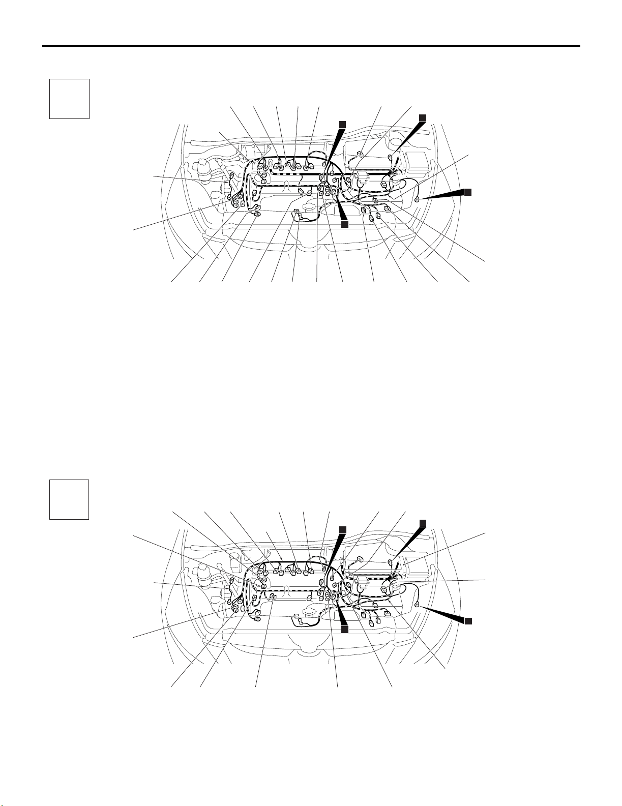
ENGINE AND TRANSMISSION <RHD>
M1801000400946
AC310306
Connector
symbol
-101
thru
-121
B
AC
B-119
B-101
B-121
B-115
B-118
B-120
B-102
B-104
B-105
Control wiring
harness
Earth cable
B-116
B-103
B-117
3
9
10
12
B-106
B-107
B-108
B-114
B-113
Battery wiring
harness
Connector colour code
B : Black
BR : Brown
G : Green
GR : Gray
L : Blue
None : Milk white
O : Orange
R : Red
V : Violet
Y : Yellow
B-110
B-109
B-111
B-112
B-101 (2-GR) Injector 1
B-102 (2-GR) Injector 2
B-103 (6-GR) Exhaust gas recirculation valve
B-104 (2-GR) Injector 3
B-105 (2-GR) Injector 4
B-106 (4-GR) Air flow sensor
B-107 (3-B) Vehicle speed sensor <M/T>
B-108 (3-GR) Output shaft speed sensor <A/T>
B-109 (10-GR) A/T control solenoid valve assembly
B-110 (2-B) Back-up lamp switch <M/T>
B-111 (10-B) Inhibitor switch <A/T>
B-112 (3-B) Input shaft speed sensor <A/T>
B-113 (1-B) Capacitor
B-114 (3-B) Camshaft position sensor
B-115 (1) Starter
B-116 (1-B) Starter
B-117 (1-B) Engine oil pressure switch
B-118 (1) Alternator
B-119 (4-GR) Alternator
B-120 (1-B) A/C compressor assembly
B-121 (3-GR) Crank angle sensor
AC310309
Connector
symbol
-01
thru
-24
B
AB
B-01
B-24
B-02
B-23
B-20B-21
B-22
B-03
B-04
B-05
Control wiring
harness
Earth cable
B-06
3
9
10
12
B-07
B-08
B-12X B-14X
B-15X B-16X
B-17
B-18
B-19
Battery wiring
harness
Connector colour code
B : Black
BR : Brown
G : Green
GR : Gray
L : Blue
None : Milk white
O : Orange
R : Red
V : Violet
Y : Yellow
B-01 (2-B) Purge control solenoid valve
B-02 (3-GR) Ignition coil 1
B-03 (3-GR) Ignition coil 2
B-04 (3-GR) Ignition coil 3
B-05 (3-GR) Ignition coil 4
B-06 (6-B) Electronic-controlled throttle valve
B-07 (2-B) Engine oil control valve
B-08 (2-B) Engine coolant temperature sensor
B-12X (4) Throttle valve control servo relay
Loading...