


CS1000
Fault Code Scanner
Mercedes-Benz
Instructions
Model Years 1988-98
Analog/Digital Fault Code Module 1988-98 |
OB15-11 |
|
|
Transmission Fault Code Module 1990-98 |
OB15-12 |
|
|
©Baum Tools Unlimited Inc. December 1, 1998
Mercedes Benz |
Code Scanner CS1000 OB15-11 |
Table of Contents
SCANNER FEATURES . . . . . . . . . . . . . . . . . . . . . . . . . . . . . . . . . . . . . . . . . . . . . . . . . . . . . . . . . . . . . . . . . 7 1. Keypad . . . . . . . . . . . . . . . . . . . . . . . . . . . . . . . . . . . . . . . . . . . . . . . . . . . . . . . . . . . . . . . . . . . . . . . 7 2. Screen Symbols . . . . . . . . . . . . . . . . . . . . . . . . . . . . . . . . . . . . . . . . . . . . . . . . . . . . . . . . . . . . . . . . 7 3. Indicator lights . . . . . . . . . . . . . . . . . . . . . . . . . . . . . . . . . . . . . . . . . . . . . . . . . . . . . . . . . . . . . . . . . 8
SECTION 1 Using the CS1000 Code Scanner . . . . . . . . . . . . . . . . . . . . . . . . . . . . . . . . . . . . . . . . . . . . 9
Diagnostic Cable . . . . . . . . . . . . . . . . . . . . . . . . . . . . . . . . . . . . . . . . . . . . . . . . . . . . . . . . . . . . . . . . . 9
General Usage Notes . . . . . . . . . . . . . . . . . . . . . . . . . . . . . . . . . . . . . . . . . . . . . . . . . . . . . . . . . . . . . . 9
Connection Table . . . . . . . . . . . . . . . . . . . . . . . . . . . . . . . . . . . . . . . . . . . . . . . . . . . . . . . . . . . . . . . . 10
Connector Layout of Vehicle Diagnostic Connector . . . . . . . . . . . . . . . . . . . . . . . . . . . . . . . . . . . . . . 10
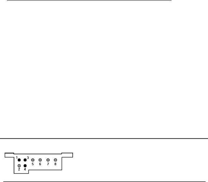
8-pole Diagnostic Connector . . . . . . . . . . . . . . . . . . . . . . . . . . . . . . . . . . . . . . . . . . . . . . . . . . . 10
16-pole Diagnostic Connector . . . . . . . . . . . . . . . . . . . . . . . . . . . . . . . . . . . . . . . . . . . . . . . . . . 11
38-Pin Diagnostic Connector . . . . . . . . . . . . . . . . . . . . . . . . . . . . . . . . . . . . . . . . . . . . . . . . . . . 12
9-Pole Diagnostic Connector (1980-94) . . . . . . . . . . . . . . . . . . . . . . . . . . . . . . . . . . . . . . . . . . . 13
Operating the CS1000 - Mercedes Benz . . . . . . . . . . . . . . . . . . . . . . . . . . . . . . . . . . . . . . . . . . . . . . . . . . . |
14 |
|
1. |
Setting Up . . . . . . . . . . . . . . . . . . . . . . . . . . . . . . . . . . . . . . . . . . . . . . . . . . . . . . . . . . . . . . . . . . . |
14 |
2. |
Ignition ON or Engine at idle . . . . . . . . . . . . . . . . . . . . . . . . . . . . . . . . . . . . . . . . . . . . . . . . . . . . . |
14 |
3. |
System Selection . . . . . . . . . . . . . . . . . . . . . . . . . . . . . . . . . . . . . . . . . . . . . . . . . . . . . . . . . . . . . . |
15 |
|
About Current, Stored and Registered Faults . . . . . . . . . . . . . . . . . . . . . . . . . . . . . . . . . . . . . . |
15 |
|
Check Engine Light Diagnosis . . . . . . . . . . . . . . . . . . . . . . . . . . . . . . . . . . . . . . . . . . . . . . . . . . |
16 |
4. |
Read Fault Codes . . . . . . . . . . . . . . . . . . . . . . . . . . . . . . . . . . . . . . . . . . . . . . . . . . . . . . . . . . . . . |
16 |
5. |
Identification/Rectification of Faults . . . . . . . . . . . . . . . . . . . . . . . . . . . . . . . . . . . . . . . . . . . . . . . . |
16 |
6. |
Clearing Fault Codes . . . . . . . . . . . . . . . . . . . . . . . . . . . . . . . . . . . . . . . . . . . . . . . . . . . . . . . . . . . |
17 |
7. |
Return to System Select Function . . . . . . . . . . . . . . . . . . . . . . . . . . . . . . . . . . . . . . . . . . . . . . . . . |
17 |
MERCEDES BENZ SYSTEM TYPE AND MODEL APPLICATIONS |
|
|
OB15-11 Software Cartridge . . . . . . . . . . . . . . . . . . . . . . . . . . . . . . . . . . . . . . . . . . . . . . . . . . . . . . |
18 |
|
ANALOG FAULT CODES
ELECTRONIC DIESEL IDLE SPEED CONTROL (ELR) |
|
|
||
201.126 |
|
|
1989 . . . . . . . . . . . . . . . . . . . . . |
. . . . . 19 |
ELECTRONIC DIESEL SYSTEM (EDS) |
|
|
||
124.128 |
|
|
1990-91 . . . . . . . . . . . . . . . . . . . |
. . . . . 20 |
126.134 |
126.135 |
|
1990-91 . . . . . . . . . . . . . . . . . . . |
. . . . . 20 |
124.128 |
|
|
1992-93 . . . . . . . . . . . . . . . . . . . |
. . . . . 21 |
140.134 |
|
|
1992-93 . . . . . . . . . . . . . . . . . . . |
. . . . . 21 |
CONTINUOUS FUEL INJECTION SYSTEM (CFI) |
|
|
||
124.026 |
124.030 |
124.050 124.090 |
1988-89 (California version only) |
. . . . . 22 |
126.024 |
126.025 |
|
1988-89 (California version only) |
. . . . . 22 |
201.028 (1988-93) |
201.029 |
1988-89 (California version only) |
. . . . . 22 |
|
107.048 |
|
|
1988-91 (California version only) |
. . . . . 22 |
126.035 |
126.039 |
126.045 |
1988-91 (California version only) |
. . . . . 22 |
124.026 |
124.030 |
124.090 124.230 124.290 |
1990-93 . . . . . . . . . . . . . . . . . . . |
. . . . . 23 |
126.024 |
126.025 |
|
1990-93 . . . . . . . . . . . . . . . . . . . |
. . . . . 23 |
201.029 |
|
|
1990-93 . . . . . . . . . . . . . . . . . . . |
. . . . . 23 |
124.051 |
129.061 |
|
1990-93 . . . . . . . . . . . . . . . . . . . |
. . . . . 25 |
129.066 |
|
|
1990-92 . . . . . . . . . . . . . . . . . . . |
. . . . . 25 |
CONTINUOUS FUEL INJECTION SYSTEM (MAS CONTROLLER) |
|
|
||
124.026 |
124.030 |
124.090 124.230 124.290 |
1990-92 . . . . . . . . . . . . . . . . . . . |
. . . . . 27 |
129.066 |
|
|
1990-92 . . . . . . . . . . . . . . . . . . . |
. . . . . 27 |
201.029 |
|
|
1990-92 . . . . . . . . . . . . . . . . . . . |
. . . . . 27 |
2
|
Mercedes Benz |
|
Code Scanner CS1000 OB15-11 |
|
|
|||
LH SEQUENTIAL MULTIPORT FUEL INJECTION SYSTEM (LH-SFI) |
|
|
|
|||||
140.032 |
140.057 |
140.076 |
|
|
1992-93 . . . . . . . . . . |
. . . . . . . . . . . . . . |
28 |
|
124.034 |
124.036 |
|
|
|
1992-93 . . . . . . . . . . |
. . . . . . . . . . . . . . |
28 |
|
129.067 |
|
|
|
|
1992-95 . . . . . . . . . . |
. . . . . . . . . . . . . . |
28 |
|
140.042 |
140.043 |
140.051 |
|
|
1992-95 . . . . . . . . . . |
. . . . . . . . . . . . . . |
28 |
|
HFM SEQUENTIAL MULTIPORT FUEL INJECTION SYSTEM |
|
|
|
|||||
104 111 |
|
|
|
|
1993-97 . . . . . . . . . . |
. . . . . . . . . . . . . . |
30 |
|
BASE MODULE (BM) |
|
|
|
|
|
|||
124.034 |
124.036 |
|
|
|
1992-93 . . . . . . . . . . |
. . . . . . . . . . . . . . |
33 |
|
129.067 |
|
|
|
|
1992-95 . . . . . . . . . . |
. . . . . . . . . . . . . . |
33 |
|
140.032 |
140.042 |
140.043 |
140.051 140.057 140.076 |
|
1992-95 . . . . . . . . . . |
. . . . . . . . . . . . . . |
33 |
|
DIAGNOSTIC MODULE (DM) |
|
|
|
|
||||
124.034 |
124.036 |
|
|
|
1992-93 . . . . . . . . . . |
. . . . . . . . . . . . . . |
34 |
|
129.067 |
|
|
|
|
1992-95 . . . . . . . . . . |
. . . . . . . . . . . . . . |
34 |
|
140.032 |
140.042 |
140.043 |
140.051 |
|
1992-95 . . . . . . . . . . |
. . . . . . . . . . . . . . |
34 |
|
140.057 |
140.076 |
|
|
|
1992-95 . . . . . . . . . . |
. . . . . . . . . . . . . . |
36 |
|
124.028 |
124.032 |
124.052 |
124.092 |
|
1994-95 . . . . . . . . . . |
. . . . . . . . . . . . . . |
39 |
|
DISTRIBUTOR IGNITION (DI) LH-SFI |
|
|
|
|
||||
140.032 |
|
|
|
|
1992-95 . . . . . . . . . . |
. . . . . . . . . . . . . . |
41 |
|
124.051 |
|
|
|
|
1990-93 . . . . . . . . . . |
. . . . . . . . . . . . . . |
43 |
|
129.061 |
129.066 |
|
|
|
1990-95 . . . . . . . . . . |
. . . . . . . . . . . . . . |
43 |
|
124.034 |
124.036 |
|
|
|
1992-93 . . . . . . . . . . |
. . . . . . . . . . . . . . |
44 |
|
129.067 |
129.076 |
|
|
|
1992-95 . . . . . . . . . . |
. . . . . . . . . . . . . . |
44 |
|
140.042 |
140.043 |
140.051 |
140.057 140.070 140.076 |
|
1992-95 . . . . . . . . . . |
. . . . . . . . . . . . . . |
44 |
|
CRUISE CONTROL/IDLE SPEED CONTROL (CC/ISC) w/o ASR |
|
|
|
|||||
124 129 |
140 202 |
|
|
1992-97 . . . . . . . . . . |
. . . . . . . . . . . . . . |
46 |
||
ELECTRONIC ACCELERATOR / CRUISE CONTROL / IDLE SPEED CONTROL (EA/CC/ISC) w/ASR |
|
|||||||
124 129 |
140 202 |
|
|
1992-97 . . . . . . . . . . |
. . . . . . . . . . . . . . |
47 |
||
ELECTRONIC AUTOMATIC TRANSMISSION CONTROL (ETC) |
|
|
|
|||||
129 w/CFI |
|
|
|
1990-93 . . . . . . . . . . |
. . . . . . . . . . . . . . |
49 |
||
129 140 w/HFM-SFI |
|
|
1993-97 . . . . . . . . . . |
. . . . . . . . . . . . . . |
50 |
|||
AUTOMATIC-ENGAGED FOUR-WHEEL DRIVE (4MATIC) |
|
|
|
|||||
124.230 |
124.290 |
|
|
|
1990-93 . . . . . . . . . . |
. . . . . . . . . . . . . . |
51 |
|
ADAPTIVE DAMPING SYSTEM (ADS) |
|
|
|
|
||||
129.061 |
129.066 |
|
|
|
1991-93 . . . . . . . . . . |
. . . . . . . . . . . . . . |
52 |
|
129.063 |
129.067 |
129.076 |
|
|
1991-95 . . . . . . . . . . |
. . . . . . . . . . . . . . |
53 |
|
140.032 |
140.042 |
140.051 |
140.057 140.070 140.076 |
140.134 |
1991-94 . . . . . . . . . . |
. . . . . . . . . . . . . . |
54 |
|
AUTOMATIC LOCKING DIFFERENTIAL (ASD) |
|
|
|
|
||||
124.128 |
|
|
|
|
1991-95 . . . . . . . . . . |
. . . . . . . . . . . . . . |
55 |
|
126.134 |
126.135 |
|
|
|
1991 . . . . . . . . . . . . |
. . . . . . . . . . . . . . |
55 |
|
129.061 |
|
|
|
|
1991-95 . . . . . . . . . . |
. . . . . . . . . . . . . . |
55 |
|
140.134 |
|
|
|
|
1991-95 . . . . . . . . . . |
. . . . . . . . . . . . . . |
55 |
|
201.028 |
|
|
|
|
1991-93 . . . . . . . . . . |
. . . . . . . . . . . . . . |
55 |
|
ANTI-LOCK BRAKE SYSTEM (ABS & ABS w/ASR)
140.032 |
140.042 |
140.043 |
140.134 |
|
1992-93 . . . . . . . . . . . . . . . . . . . . . . . . |
56 |
|
124.034 |
124.036 |
|
|
|
1992-93 . . . . . . . . . . . . . . . . . . . . . . . . |
57 |
|
140.032 |
140.042 |
140.051 |
140.057 |
140.070 140.076 |
1992-93 . . . . . . . . . . . . . . . . . . . . . . . . |
57 |
|
202 |
210 |
|
|
|
1994-95 . . . . . . . . . . . . . . . . . . . . . . . . |
59 |
|
124.034 |
|
|
|
|
1994-95 . . . . . . . . . . . . . . . . . . . . . . . . |
60 |
|
129 |
|
|
|
|
|
1994-95 . . . . . . . . . . . . . . . . . . . . . . . . |
60 |
140 |
|
|
|
|
|
1994-95 . . . . . . . . . . . . . . . . . . . . . . . . |
60 |
3
|
Mercedes Benz |
|
Code Scanner CS1000 OB15-11 |
|
|
||||
1. |
|
|
|
|
|
|
ELECTRONIC TRACTION SYSTEMS |
|
|
|
|
|
|
|
|
|
(ASR, ETS) |
|
|
129 |
140 |
202 |
|
|
|
1995 . . . . . . . . . . . . |
. . . . . . . . . . . . . |
. 61 |
|
210 |
|
|
|
|
|
1995-96 . . . . . . . . . . |
. . . . . . . . . . . . . . |
61 |
|
SPEED SENSITIVE POWER STEERING (SPS) |
|
|
|
|
|||||
140.032 |
140.042 |
140.051 |
140.057 140.070 140.076 |
140.134 |
1992-93 . . . . . . . . . . |
. . . . . . . . . . . . . . |
63 |
||
140 |
|
|
|
|
|
1994 . . . . . . . . . . . . |
. . . . . . . . . . . . . . |
64 |
|
CABRIOLET SOFT TOP (CST7 |
|
|
|
|
|||||
124.066 |
|
|
|
|
1993-95 . . . . . . . . . . |
. . . . . . . . . . . . . . |
65 |
||
ROLL BAR (RB) |
|
|
|
|
|
|
|||
124.066 |
|
|
|
|
1993-95 . . . . . . . . . . |
. . . . . . . . . . . . . . |
66 |
||
129.061 |
129.066 |
129.067 |
129.076 |
|
1990-12/93 . . . . . . . |
. . . . . . . . . . . . . . |
67 |
||
ROADSTER SOFT TOP (RST) |
|
|
|
|
|||||
129.061 |
129.066 |
129.067 |
129.076 |
|
1990-93 . . . . . . . . . . |
. . . . . . . . . . . . . . |
68 |
||
129 |
|
|
|
|
|
1/94-6/96 . . . . . . . . . |
. . . . . . . . . . . . . . |
70 |
|
INFRARED REMOTE CONTROL FOR CENTRAL LOCKING (IRCL) |
|
|
|
||||||
129.061 |
129.066 |
129.067 |
129.076 |
|
1990-93 . . . . . . . . . . |
. . . . . . . . . . . . . . |
71 |
||
140 |
|
|
|
|
|
1990-96 . . . . . . . . . . |
. . . . . . . . . . . . . . |
72 |
|
129 |
|
|
|
|
|
1993-96 . . . . . . . . . . |
. . . . . . . . . . . . . . |
73 |
|
PNEUMATIC SYSTEMS EQUIPMENT (PSE) |
|
|
|
|
|||||
129 |
140 |
202 |
|
|
|
1992-94 . . . . . . . . . . |
. . . . . . . . . . . . . . |
74 |
|
ANTI-THEFT ALARM SYSTEM(ATA) |
|
|
|
|
|||||
129.061 |
129.066 |
129.067 |
129.076 |
|
1990-93 . . . . . . . . . . |
. . . . . . . . . . . . . . |
75 |
||
140.032 |
140.042 |
140.051 |
140.057 140.070 140.076 |
140.134 |
1990-93 . . . . . . . . . . |
. . . . . . . . . . . . . . |
75 |
||
129 |
140 |
202 |
|
|
|
1994-96 . . . . . . . . . . |
. . . . . . . . . . . . . . |
75 |
|
CELLULAR TELEPHONE (CT) |
|
|
|
|
|||||
129.061 |
129.066 |
129.067 |
129.076 |
|
1992-95 . . . . . . . . . . |
. . . . . . . . . . . . . . |
76 |
||
140.032 |
140.042 |
140.051 |
140.057 140.070 140.076 |
140.134 |
1992-95 . . . . . . . . . . |
. . . . . . . . . . . . . . |
76 |
||
CONVENIENCE FEATURES (CF) |
|
|
|
|
|||||
140 |
|
|
|
|
|
1992-96 . . . . . . . . . . |
. . . . . . . . . . . . . . |
77 |
|
TEMPMATIC A/C |
|
|
|
|
|
|
|||
201.028 |
201.029 |
201.034 |
201.126 201.128 |
|
1988-93 . . . . . . . . . . |
. . . . . . . . . . . . . . |
79 |
||
A/C |
|
|
|
|
|
|
|
|
|
124.034 |
124.036 |
|
|
|
1992-95 . . . . . . . . . . |
. . . . . . . . . . . . . . |
81 |
||
124.026 |
124.030 |
124.050 |
124.090 124.051 124.230 |
124.290 |
1988-95 . . . . . . . . . . |
. . . . . . . . . . . . . . |
82 |
||
126.024 |
126.025 |
126.035 |
126.039 126.045 126.134 |
126.135 |
1988-91 . . . . . . . . . . |
. . . . . . . . . . . . . . |
82 |
||
A/C SELF DIAGNOSTIC SYSTEMS |
|
|
|
|
|||||
TAU 2.1 |
|
|
|
|
. . . . . . . . . . . . . . . . |
. . . . . . . . . . . . . . |
83 |
||
129 Chassis |
|
|
|
1990-95 . . . . . . . . . . |
. . . . . . . . . . . . . . |
86 |
|||
129 Chassis |
|
|
|
1996-98 . . . . . . . . . . |
. . . . . . . . . . . . . . |
89 |
|||
140 Chassis |
|
|
|
1992-95 . . . . . . . . . . |
. . . . . . . . . . . . . . |
92 |
|||
140 Chassis |
|
|
|
1996-97 . . . . . . . . . . |
. . . . . . . . . . . . . . |
98 |
|||
202 Chassis |
|
|
|
1995 . . . . . . . . . . . . |
. . . . . . . . . . . . . |
101 |
|||
202 Chassis |
|
|
|
1996-98 . . . . . . . . . . |
. . . . . . . . . . . . . |
107 |
|||
210 Chassis |
|
|
|
1996-98 . . . . . . . . . . |
. . . . . . . . . . . . . |
110 |
|||
SUPPLEMENTAL RESTRAINT SYSTEM (SRS) |
|
|
|
|
|||||
107 |
126 |
140 201 |
|
|
1988-93 . . . . . . . . . . |
. . . . . . . . . . . . . |
113 |
||
124 |
129 |
|
|
|
|
1990-93 . . . . . . . . . . |
. . . . . . . . . . . . . |
114 |
|
4
|
Mercedes Benz |
|
Code Scanner CS1000 OB15-11 |
|
|
||
DIGITAL FAULT CODE SYSTEMS |
2 - 12 . . . . . . . . . . . . . . . . . . . . . |
. . . . . . . . . . . |
115 |
||||
|
2 SUPPLEMENTAL RESTRAINT SYSTEM (SRS) BAE, ZAE SYSTEM |
|
|||||
129 |
140 |
124 |
|
1994-1995 . . . . . . . . |
. . . . . . . . . . . . . |
116 |
|
202 |
210 |
|
|
Beginning of manufacture -1995 . . . . . |
116 |
||
|
3 SUPPLEMENTAL RESTRAINT SYSTEM (SRS) WITH SIDE AIRBAGS |
|
|||||
129 |
(R) 140 (S) |
202 (C) 210 (E) |
1996 - 98 . . . . . . . . . |
. . . . . . . . . . . . . |
117 |
||
|
4 - 5 LH SEQUENTIAL MULTIPORT FUEL INJECTION SYSTEM (LH-SFI) |
|
|||||
104 |
119 |
120 |
|
1991-1993 . . . . . . . . |
. . . . . . . . . . . . . |
118 |
|
|
6 - 7 HFM SEQUENTIAL MULTIPORT FUEL INJECTION SYSTEM (HFM-SFI) |
|
|||||
111 |
(4 cylinder, 2.2/2.3L engine) |
1994-1997 . . . . . . . . |
. . . . . . . . . . . . . |
122 |
|||
104 |
(6 cylinder, 2.8/3.2L engine) |
1994-1997 . . . . . . . . |
. . . . . . . . . . . . . |
122 |
|||
|
6 - 7 PMS FUEL INJECTION SYSTEM |
|
|
|
|||
111 |
(4 cylinders, 1.8/2.0L engine) |
1994-1997 . . . . . . . . |
. . . . . . . . . . . . . |
127 |
|||
8, |
9 & |
10 DIAGNOSTIC MODULE (DM) |
|
||||
104 |
119 |
120 |
|
1991-1996 . . . . . . . . |
. . . . . . . . . . . . . |
131 |
|
11 - |
12 ME SEQUENTIAL MULTIPORT FUEL INJECTION SYSTEM (ME-SFI) . . . . . . . . . . |
134 |
|||||
TRANSMISSION MODULE OB15-12 INSTRUCTIONS . . . . . . . . . . . . . . . . . . . . . . . |
141 |
||||||
|
ANALOG FAULT CODES |
|
|
|
|||
124.230 124.290 |
w/CFI |
1990-93 . . . . . . . |
. . . . . . . . . . . . . |
144 |
|||
129 |
w/CFI |
|
1990-93 . . . . . . . |
. . . . . . . . . . . . . |
145 |
||
|
129 140 w/LH-SFI |
1990-93 . . . . . . . |
. . . . . . . . . . . . . |
146 |
|||
|
DIGITAL FAULT CODES |
|
|
|
|||
129 |
140 |
163 170 202 208 210 w/ME-SFI |
1995-98 . . . . . . . |
. . . . . . . . . . . . . |
147 |
||
129 |
140 |
w/LH-SFI or HFM-SFI |
1993-96 . . . . . . . |
. . . . . . . . . . . . . |
150 |
||
MERCEDES TECHNICAL ACRONYMS . . . . . . . . . . . . . . . . . . . . . . . . . . . . . . . . . . . . . . . . . . . . . 151
MERCEDES MODEL IDENTIFIER . . . . . . . . . . . . . . . . . . . . . . . . . . . . . . . . . . . . . . . . . . . . . . . . . . 154
5
Mercedes Benz |
Code Scanner CS1000 OB15-11 |
DISCLAIMER: ALL INFORMATION CONTAINED IN THIS DOCUMENT IS CORRECT TO THE BEST OF OUR KNOWLEDGE. ERRORS MAY OCCUR THEREFORE BAUM TOOLS UNLIMITED INC. MAKES NO WARRANTEE, GUARANTEE OR ASSURANCE THAT DAMAGE MAY NOT OCCUR FROM THE USE OF THIS INFORMATION. THE USER TAKES ALL RESPONSIBILITY FOR ITS USE.
LIMITATION OF WARRANTIES AND LIABILITY: THE PRODUCT IS PROVIDED ON AN "AS IS" BASIS, WITHOUT ANY OTHER WARRANTIES OR CONDITIONS, EXPRESS OR IMPLIED, INCLUDING, BUT NOT LIMITED TO, WARRANTIES OF MERCHANTABLE QUALITY, MERCHANTABILITY OR FITNESS FOR A PARTICULAR PURPOSE, OR THOSE ARISING BY LAW, STATUTE, USAGE OF TRADE, OR COURSE OF DEALING. THE ENTIRE RISK AS TO THE RESULTS AND PERFORMANCE OF THE PRODUCT IS ASSUMED BY YOU. NEITHER WE NOR OUR DEALERS OR SUPPLIERS SHALL HAVE ANY LIABILITY TO YOU OR ANY OTHER PERSON OR ENTITY FOR ANY INDIRECT, INCIDENTAL, SPECIAL, OR CONSEQUENTIAL DAMAGES WHATSOEVER, INCLUDING, BUT NOT LIMITED TO, LOSS OF REVENUE OR PROFIT, LOST OR DAMAGED DATA OR OTHER COMMERCIAL OR ECONOMIC LOSS, EVEN IF WE HAVE BEEN ADVISED OF THE POSSIBILITY OF SUCH DAMAGES, OR THEY ARE FORESEEABLE. WE ARE ALSO NOT RESPONSIBLE FOR CLAIMS BY A THIRD PARTY. OUR MAXIMUM AGGREGATE LIABILITY TO YOU AND THAT OF OUR DEALERS AND SUPPLIERS SHALL NOT EXCEED THE AMOUNT PAID BY YOU FOR THE PRODUCT. THE LIMITATIONS IN THIS SECTION SHALL APPLY WHETHER OR NOT THE ALLEGED BREACH OR DEFAULT IS A BREACH OF A FUNDAMENTAL CONDITION OR TERM OR A FUNDAMENTAL BREACH. SOME STATES/COUNTRIES DO NOT ALLOW THE EXCLUSION OR LIMITATION OF LIABILITY FOR CONSEQUENTIAL OR INCIDENTAL DAMAGES, SO THE ABOVE LIMITATION MAY NOT APPLY TO YOU.
Mercedes Benz is a registered trademark of Daimler Benz AG.
Copyright © 1998 BAUM TOOLS UNLIMITED INC.
All rights reserved. Any reproduction in whole or in part is strictly prohibited.
6

Mercedes Benz |
Code Scanner CS1000 OB15-11 |
SCANNER FEATURES
1. Keypad
SYSTEM Select vehicle control system for code reading and erasing.
READ Read fault codes.
NEXT 2. View next fault code. (If more than one fault code present)
CLEAR Clear fault codes.
2. Screen Symbols
. .
U
I
0000
Control systems select.
Scanner is Reading or Clearing fault code
Indicate fault code list number to use.
Indicate fault code.
Four 0s flashing together.
Connection fault or vehicle not equipped with this system
»Check that the Ignition key is on or the Engine is running.
»Check power requirement to scanner (10.5 to 14.5 Volts)
»Check the in-line fuse on the Yellow probe wire.
»Check for correct connection to the Vehicle Diagnostic Connector.
»Check for short circuit in the Vehicle Diagnostic Connector.
»Check that this memory cartridge is available for this vehicle system.
»Check that vehicle system requested for test is fitted to this vehicle.
7

Mercedes Benz |
Code Scanner CS1000 OB15-11 |
3. Indicator lights
Power indicator (Red LED light)
Data link indicator (Green LED light). Receive data from the control unit.
Data link indicator (Yellow LED light). Transfer data to the control unit.
8

Mercedes Benz |
Code Scanner CS1000 OB15-11 |
SECTION 1 Using the CS1000 Code Scanner
Diagnostic Cable
General Usage Notes
The OB15 Code Scanner can display available fault codes from Mercedes Benz vehicles fitted with 8-pole, 16-pole and 38-pole Diagnostic Connectors. The Red wire from the scanner is for powering up the unit and is taken either from the power source socket on the Diagnostic Connector, if available, or from the vehicle battery, using the extension cable supplied. The Black earth wire from the scanner is grounded to the earth socket on the Diagnostic Connector. The Yellow wire from the scanner is used to read the codes from the Diagnostic Connector.
The P/N 15-C2 diagnostic cable must be used with the P/N 15-C2-1 diagnostic cable for the 38-pole vehicle diagnostic connector.
9
Mercedes Benz Code Scanner CS1000 OB15-11
Connection Table
Test Lead of Cable |
Connection source |
Red |
Power -To power supply socket or vehicle battery |
Black |
Ground - To socket 1 |
Yellow |
To diagnostic test socket |
Power supply (B+) socket on the vehicle Diagnostic Connectors
8-pole connector |
Use with the battery extension cable to the vehicle battery |
16-pole connector |
Socket 16 (circuit 15 - ignition ON)* |
|
Not present in some models. Use battery +. |
38-pole connector |
Socket 3 (circuit 30 - Battery+) |
*Must be performed with the ignition ON to power up the scanner. |
|
Ground (-) socket on the vehicle Diagnostic Connectors |
|
8-pole connector |
socket 1 |
16-pole connector |
socket 1 |
38-pole connector |
socket 1 |
Connector Layout of Vehicle Diagnostic Connector
8-pole Diagnostic Connector
Models 201, 124, 126
1 |
|
Ground |
2 |
|
Not used |
3 |
CIS-E |
Continuous fuel injection system (CFI) |
4 |
ELR |
Diesel injection system - Electronic idle speed control system |
|
EDS |
Electronic diesel system |
5 |
ASD |
Automatic locking differential |
|
4MATIC |
Automatic-engaged four wheel drive (124 only) |
6 |
SRS |
Supplemental Restraint System |
7 |
A/C |
Air Conditioning |
8 |
|
Not used |
10
Mercedes Benz |
Code Scanner CS1000 OB15-11 |
16-pole Diagnostic Connector
Models 124, 129
1 |
|
Ground |
2 |
OBD |
Push-button for On Board Diagnostic (California only) |
3 |
CIS-E |
Continuous Fuel injection system (CFI) |
|
DM |
Diagnostic Module - LED (California only) |
4 |
EDS |
Electronic diesel system |
5 |
ASD |
Automatic locking differential |
|
4MATIC |
Automatic-engaged four wheel drive |
6 |
SRS / AB |
Supplemental Restraint System / Air Bag |
7 |
A/C |
Air Conditioning (Model 124) |
|
RB |
Roll Bar (Model 129) |
8 |
DI |
Distributor ignition |
|
HFM-SFI |
HFM Sequential multi-port Fuel Injection/Ignition system |
|
PEC |
Pressurized engine control |
9 |
ADS |
Adaptive Damping System |
|
RB |
Roll Bar (Model 124) |
10 |
RST |
Roadster Soft Top (Model 129) |
|
|
TN-signal (Gasoline) |
11 |
ATA |
Anti Theft Alarm system |
12 |
IRCL |
Infrared Remote Central Locking |
13 |
ETC |
Electronic automatic Transmission Control |
14 |
EA |
Electronic Accelerator (Model 124) |
|
CC / ISC |
Cruise Control / Idle Speed Control (Model 124) |
|
ESCM |
Engine System Control Module (MAS), (Model 129) |
15 |
|
Not used |
16 |
|
Voltage, Ignition ON (Circuit 15) (Not equipped on all models.) |
11
Mercedes Benz |
Code Scanner CS1000 OB15-11 |
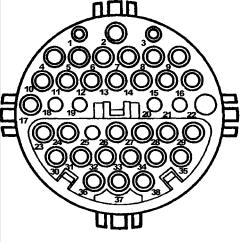
38-Pin Diagnostic Connector
Models 124.034/036, 129.058/063/067/076, 140, 170, 202, 208, 210
The Mercedes Diagnostic “Mushroom” #140-1463 available from Baum Tools Unltd. is recommended to allow easy access to the diagnostic connector. Call 800-848-6657 or 941- 927-1414 for more information.
Pin |
System |
Description |
|
|
|
1 |
Ground (Terminal 31) |
W12 (Chassis Ground), W15 (Electronics Ground) |
|
|
|
2 |
Voltage, terminal 87 |
Ignition Switch 12volts + |
|
|
|
3 |
Voltage, terminal 30 |
Battery 12volts + |
|
|
|
4 |
EDS |
Electronic Diesel System |
|
|
|
|
IFI |
In-line Fuel Injection |
|
|
|
|
DFI |
Electronic Distributor-type Fuel Injection (Diesel) |
|
|
|
|
HFM-SFI |
Hot-Film Engine Management Sequential Multiport Fuel Injection/ignition |
|
|
|
|
LH-SFI |
LH Sequential Multiport Fuel Injection System |
|
|
Engines 104, 119 |
|
|
Engine 120 Right Bank |
|
|
|
|
ME-SFI |
Motor Electronics with Sequential Multiport Fuel Injection/ignition System |
|
|
Engine 119 |
|
|
Engine 120, Right Bank |
|
|
|
5 |
LH-SFI |
LH Sequential Multiport Fuel Injection, Engine 120 Left Bank |
|
|
|
|
ME-SFI |
Motor Electronics with Sequential Multiport Fuel Injection/ignition System |
|
|
Engine 120 Left Bank |
|
|
|
6 |
ABS |
Anti-lock Brake System |
|
|
|
|
ETS |
Electronic Traction System |
|
|
|
|
ASR |
Acceleration Slip Regulation |
|
|
|
|
ESP |
Electronic Stability Program |
|
|
|
7 |
EA |
Electronic Accelerator+ |
|
|
|
|
ISC |
Idle Speed Control |
|
|
|
|
CC |
Cruise Control/idle Speed Control |
|
|
|
8 |
BM |
Base Module |
|
|
|
|
BAS |
Brake Assist |
|
|
|
9 |
ASD |
Automatic Locking Differential, Models 124, 129, 140 |
|
|
|
10 |
EATC |
Electronic Automatic Transmission Control (5-speed AT) (722.6) |
|
|
|
|
ETC |
Electronic Transmission Control (722.6) |
|
|
|
11 |
ADS |
Adaptive Damping System |
|
|
|
12
|
Mercedes Benz |
Code Scanner CS1000 OB15-11 |
|
|
|
|
|
||
12 |
SPS |
Speed-sensitive Power Steering |
||
|
|
|
||
13 |
TD |
Speed Signal (Time Division) (Di) (Diesel) Models 202, 210 |
||
|
|
|
|
|
|
|
TNA |
Signal (Gasoline) on LH-SFI |
|
|
|
|
|
|
|
|
TN |
Speed Signal (DI/KSS) (Gasoline) on HFM-SFI, ME-SFI |
|
|
|
|
||
14 |
Lambda on/off ratio |
LH-SFI Engine 119, |
||
|
|
|
LH-SFI Engine 120 LH-SFI, Right Bank |
|
|
|
|
||
15 |
Lambda on/off ratio |
LH-SFI Engine 120 Left Bank |
||
|
|
|
|
|
|
|
IC |
Instrument Cluster |
|
|
|
|
||
16 |
HEAT |
Automatic Heater |
||
|
|
|
|
|
|
|
TA/C |
Air Conditioning (Tempmatic) |
|
|
|
|
|
|
|
|
AA/C |
Air Conditioning (Automatic) |
|
|
|
|
||
17 |
DI |
Distributor Ignition, Engines 104, 119, Engine 120, Right |
||
|
|
|
|
|
|
|
TD |
Speed Signal (Time Division) (Di) (Diesel) Model 140 |
|
|
|
|
|
|
|
|
TN |
Speed Signal (DI/KSS) (Gasoline) on LH-SFI / model 202 HFM-SFI |
|
|
|
|
||
18 |
DI |
Distributor Ignition, Engine 120, Left |
||
|
|
|
||
19 |
DM |
Diagnostic Module |
||
|
|
|
||
20 |
PSE |
Pneumatic System Equipment, Model 140 |
||
|
|
|
|
|
|
|
MFCM |
Multi-function Control Module, Model 210 |
|
|
|
|
||
21 |
CF |
Convenience Feature, Model 140 |
||
|
|
|
|
|
|
|
RST |
Roadster Soft Top, Model 129 |
|
|
|
|
||
22 |
RB |
Roll Bar, Model 129 |
||
|
|
|
||
23 |
ATA |
Anti-theft Alarm |
||
|
|
|
|
|
24-25 |
- |
|
|
|
|
|
|
||
26 |
ASD |
Automatic Locking Differential, Model 202 |
||
|
|
|
|
|
27 |
- |
|
|
|
|
|
|
||
28 |
PTS |
Parktronic System, Model 140 |
||
|
|
|
|
|
29 |
- |
|
|
|
|
|
|
||
30 |
AB |
Airbag/emergency Tensioning Retractor |
||
|
|
|
||
31 |
RCL |
Remote Central Locking |
||
|
|
|
|
|
32-33 |
- |
|
|
|
|
|
|
||
34 |
CNS |
Communication and Navigation System |
||
|
|
|
|
|
35 |
- |
|
|
|
|
|
|
||
36 |
STH |
Stationary Heater |
||
|
|
|
||
36 |
ZUH |
Heater Booster |
||
|
|
|
|
|
37-38 |
- |
|
|
|
9-Pole Diagnostic Connector (1980-94)
The 9-pole Diagnostic Connector is used on earlier model vehicles. It can display on-off ratio fault codes (1986 and later), RPM and Lambda sensor values. Various on-off ratio Meters are available that provide access to this type of diagnostic connector. Call Baum Tools at 800-848-6657 or 941-927-1414 for more information on these meters.
13

Mercedes Benz |
Code Scanner CS1000 OB15-11 |
Operating the CS1000 - Mercedes Benz
OB15-11 Memory Cartridge - Mercedes Benz Analog & Digital Fault Codes
1. Setting Up
ATTENTION: DO NOT INSERT CARTRIDGE WITH POWER SUPPLIED TO THE CS1000.
PROPER USE OF THE MERCEDES DIAGNOSTIC SYSTEM
Identify vehicle Model and Month/Year of production
Confirm specific drivability complaint. If MIL is on, when did it come on and under what conditions?
Insert the OB15-11 memory cartridge into the base of the scanner. Make sure the arrow on the cartridge is facing up as it is inserted. Gently push the cartridge into the CS1000 until the cartridge seats completely.
Refer to Diagnostic Cable introduction page 9 and connection table page 10 of this manual to determine vehicle cable requirements. Connect the cable specified to the scanner and to the vehicle Diagnostic Connector.
Connect the 25-pin cable connector head firmly to the scanner 25-pin connection port.
Connect the Red test lead from the scanner to the power supply socket (B+) on the Diagnostic Connector, where available, or to the vehicle's battery via the extension cable and battery clamp supplied.
Connect the Black test lead from the scanner to the ground socket on the Diagnostic Connector. Now the
scanner powered up and the power indicator light should be fully illuminated. The screen will display E 1.
Note:
Power indicator light (LED) must light up. If it does not, refer to the list below for detailed test.
Refer to the connection table of this manual; check the Red and Black test lead with the socket number on the Diagnostic Connector, Is there an incorrect or weak connection?
Check the power requirement on the Diagnostic Connector. (Must be performed with the ignition ON when connected with 16-pole diagnostic connector at socket 16)
Connect the Yellow test lead to the system diagnostic socket that you use to extract codes.
Refer to this manual or Mercedes Benz maintenance manual for location of the Diagnostic sockets for the type of Diagnostic Connector fitted to the vehicle and the system capabilities available for code access on the applicable Diagnostic sockets.
2. Turn Ignition ON (KOEO) or Engine at idle (KOER)
14

Mercedes Benz |
Code Scanner CS1000 OB15-11 |
3. System Selection
1
2
3
4
5
6
7
8
9
10
11
12
All analog impulse fault code systems. If unsure, start with this system.
Digital type SRS (1 or 2 airbag) system as follows:
1. W202 © class). 2. W129 / W140 1993 - 1996
Digital type SRS (4 airbags)
1. W210 (E class). 2. W129 / W140 1996 1998
Digital type LH-SFI for the Current fault codes. 1991-1993 Digital type LH-SFI for the Stored fault codes. 1991-1993
Digital type HFM-SFI for the Current fault codes. 1993-1997 Digital type PMS for the Current fault codes. 1993-1996 Digital type HFM-SFI for the Stored fault codes. 1993-1997 Digital type PMS for the Stored fault codes. 1993-1996
Digital type DM for the Current fault codes. 1991-1996 Digital type DM for the Stored fault codes. 1991-1996 Digital type DM for the Registered fault codes. 1991-1996
Digital type ME-SFI for the Current fault codes. 1996-1998 Digital type ME-SFI for the Stored fault codes. 1996-1998
Press the SYSTEM key to scroll to display from 1 to 2 system etc....
SYSTEM
ANALOG TEST PROCEDURES
1.Ignition in the KOEO position (Key On Engine Off)
2.Choose system 1
3.Place test probe (yellow) in pin-out for specific analog test.
DIGITAL TEST PROCEDURE
1.Ignition in the KOEO position (Key On Engine Off)
2.Choose system 2 thru 12
3.Place test probe (yellow) in pin-out for specific analog test.
4.If any system does not respond, test it using the Analog Test Procedure.
*Some early LH Injection and Diagnostic Module systems may not respond to the digital test.
15

Mercedes Benz |
Code Scanner CS1000 OB15-11 |
4. Read Fault Codes
Press the READ key to begin to read the fault codes for the system selected. The scanner will scan all of the fault codes and keep them in memory.
|
|
|
|
READ |
|
|
|
|
|
xx . The display will cycle to the first code after |
|
Press the NEXT key to scroll through the fault codes |
|||
the last code is displayed. When there are no faults in the system, |
0 will be displayed on the screen. |
||
NEXT
There are 5 digital numbers for fault code for the ME-SFI control system, the fault code will automatically display 1 digital number first then 4 digital numbers later. For example, the fault code 1234 will display C 0 then 1 2 3 4 . C 0 stands for (Power-train system)
5678 will display C |
1 then 5 6 7 8 . |
C |
1 stands for |
(Chassis system) |
0110 will display C |
2 then 0 1 1 0 . |
C |
2 stands for |
(Body system) |
4321 will display C |
3 then 4 3 2 1 . |
C |
3 stands for |
(Unspecified system) |
5.Identification/Rectification of Faults
A.Identify fault code and related circuit using this manual or using the factory diagnostic manuals available from Baum Tools Technical Publications 415-566-9229.
B.Carry out required repair before clearing fault codes.
About Current, Stored and Registered Faults
Current Faults - These faults are detected while the car is running at idle or speed. They represent components currently failing. These codes cannot be erased, and are only meaningful with the ignition on and the engine running. Codes found in this system with the KOEO have no meaning. Components not present on the vehicle may be flagged as failing by the cars internal diagnostics due to the generic nature of the cars software. This is particularly true in C-Class (202) cars.
Stored or Permanent Faults - These faults are recorded in the permanent memory of the cars system controller and are the main cause of MIL illumination. These codes can be erased.
Registered Faults - These faults are recorded in the temporary memory of the of the cars system controller. This temporary memory records the number of times a component fails. When a certain number of failures has occurred the fault is moved to permanent storage and the Check Engine Light (MIL) will be illuminated. On cars equipped with Fault Registers the Check Engine Light may stay on after the Stored or Permanent Fault has been erased if another occurrence of the fault has happened since the Permanent Fault was stored. To extinguish the light erase the Stored and Registered faults. These codes can be erased.
16

Mercedes Benz |
Code Scanner CS1000 OB15-11 |
Check Engine Light Diagnosis
Mercedes S(140), SL(129), E(210) and C(202) class have multiple systems which can turn on an Check Engine Light. All related systems must be tested for codes and repaired before the light will extinguish.
129 |
LH |
LH (pin 4 & 5) EA/CC/ISC (pin 7), BM (pin 8), DI (pin 17 & 18) and DM (pin 19) |
|
|
|
140 |
LH |
LH (pin 4) EA/CC/ISC (pin 7), BM (pin 8), DI (pin 17) and DM (pin 19) |
|
|
|
124 |
HFM |
HFM (pin 8) EA/CC/ISC (pin 14), and DM (pin 3) |
|
|
|
140 |
HFM |
HFM (pin 4) EA/CC/ISC (pin 7), BM (pin 8), DI (pin 17) and DM (pin 19) |
|
|
|
202 |
HFM |
HFM (pin 4) EA/CC/ISC (pin 7) (except C220) and DM (pin 19) |
|
|
|
210 |
HFM |
HFM (pin 4) EA/CC/ISC (pin 7), BM (pin 8), DI (pin 17) and DM (pin 19) |
|
|
|
6. Clearing Fault Codes
After repairs have been carried out reread the codes. After rereading the codes press the CLEAR key to erase all of the fault codes from the control unit memory. When there are no faults in the system, either 1
(Impulse or analog systems) or 2 (digital systems) will be displayed on the screen.
CLEAR
7. Return to System Select Function
Press the SYSTEM key to scroll through the system selections.
SYSTEM
17
Mercedes Benz |
Code Scanner CS1000 OB15-11 |
Mercedes Benz System Type and Model Applications
OB15-11 Software Cartridge
The Code Scanner will read and clear the fault codes for the following System applications and Year models. Refer to the table of contents section 3 or to system malfunction tables of this manual to determine vehicle model and year.
ANALOG/DIGITAL MODULE OB15-11
SYSTEM |
DESCRIPTION |
ANALOG |
DIGITAL |
|
|
|
|
A/C |
Air Conditioning / Heating |
1988-93 |
|
|
|
|
|
ABS |
Anti-lock Brake System |
1992-95 |
1992-97 |
|
|
|
|
ADS |
Automatic Damping System (Suspension) |
1991-93 |
|
|
|
|
|
ASD |
Automatic Locking Differential |
1991-93 |
|
|
|
|
|
ASR |
Acceleration Slip Regulation |
1992-95 |
1992-97 |
|
|
|
|
ATA |
Anti-theft Alarm System |
1990-95 |
|
|
|
|
|
BM |
Base Module (Master ECU Controller) |
1992-95 |
|
|
|
|
|
CC |
Cruise Control (Tempomat) |
1992-95 |
|
|
|
|
|
CF |
Convenience Feature |
1992-95 |
|
|
|
|
|
CFI |
Continuous Fuel Injection (CIS-E) |
1988-92 |
|
|
|
|
|
CST |
Cabriolet Soft Top |
1993-95 |
|
|
|
|
|
DI |
Distributor Ignition System |
1990-93 |
|
|
|
|
|
DM (USA) |
Diagnostic Module (Emissions) |
1990-93 |
1991-98 |
|
|
|
|
EA |
Electronic Accelerator |
1992-95 |
|
|
|
|
|
EDS |
Electronic Diesel System |
1990-93 |
|
|
|
|
|
ELR |
Diesel Electronic Idle Speed Control |
1989 |
|
|
|
|
|
HFM-SFI |
Hot Film Engine Management |
1993-95 |
1994-97 |
|
|
|
|
IRCL |
Infrared Remote Central Locking |
1990-95 |
|
|
|
|
|
ISC |
Idle Speed Control |
1992-95 |
|
|
|
|
|
KE |
Continuous Injection System (CIS-E) |
1987-92 |
|
|
|
|
|
LH-SFI |
LH Sequential Fuel Management |
1990-93 |
1991-93 |
|
|
|
|
MAS |
Engine System Control Module (Mas) |
1990-93 |
|
|
|
|
|
ME-SFI |
Motor Electronic Injection |
|
1996-98 |
|
|
|
|
PMS |
|
1993-95 |
1994-97 |
|
|
|
|
PSE |
Pneumatic System Equipment |
1992-95 |
|
|
|
|
|
RB |
Roll Bar Control |
1990-95 |
|
|
|
|
|
RST |
Roadster Soft Top |
1992-95 |
|
|
|
|
|
SPS |
Speed-sensitive Power Steering |
1992-95 |
|
|
|
|
|
SRS |
Supplemental Restraint System (Airbag) |
1988-93 |
1993-98 |
|
|
|
|
TRANSMISSION MODULE OB15-12
4MATIC |
4 Wheel Drive Transmission Control |
1990-93 |
1993-95 |
|
|
|
|
ETC/EGS |
Electronic Transmission Control |
1990-93 |
1993-97 |
|
|
|
|
18
19

1 ANALOG CODES
CS1000 Code Scanner OB15-11
Model |
|
Model Year |
|
|
|
|
|
201.126 |
|
1989 |
|
|
|
|
|
Connect wires of Scanner as follows: |
|||
Scanner |
Data Link Connector 8-pin |
|
|
|
|
|
|
Yellow |
Socket 4 |
|
|
|
|
|
|
Black |
Socket 1 |
|
|
|
|
|
|
Red |
Battery (+) |
|
|
|
|
|
|
FAULT CODE TABLE
DTC Readout |
Possible Cause of Failure |
|
|
1 |
No fault found |
|
|
2 |
Speed sensor signal |
|
|
3 |
Coolant temperature sensor signal |
|
|
4 |
ELR control unit or Idle speed control (ISC) system |
|
|
20
1 ANALOG CODES
CS1000 Code Scanner OB15-11
Model |
|
|
|
|
Model Year |
|
|
|
|
|
|
|
|
|
|
124.128 |
|
|
|
|
1990-91 |
|
|
|
|
|
|
|
|
|
|
126.134 |
126.135 |
|
1990-91 |
|
|
||
|
|
|
|
|
|
||
Connect wires of Scanner as follows: |
|||||||
Scanner |
|
Data Link Connector 8-pin |
|
||||
|
|
|
|
|
|||
Yellow |
|
Socket 4 |
|
|
|||
|
|
|
|
|
|||
Black |
|
Socket 1 |
|
|
|||
|
|
|
|
|
|||
Red |
|
Battery (+) |
|
|
|||
|
|
|
|
||||
FAULT CODE TABLE |
|||||||
DTC Readout |
|
Possible Cause of Failure |
|||||
|
|
|
|
|
|||
1 |
|
|
|
No fault found |
|||
|
|
|
|
|
|||
2 |
|
|
|
Fuel rack position sensor (L7) |
|||
|
|
|
|
|
|||
3 |
|
|
|
Air flow sensor (B2/1) |
|||
|
|
|
|
|
|||
4 |
|
|
|
EDS control unit (N39), atmospheric pressure sensor |
|||
|
|
|
|
|
|||
5 |
|
|
|
EGR valve vacuum transducer (Y31/1) or malfunction in EGR control circuit |
|||
|
|
|
|
|
|||
6 |
|
|
|
EDS control unit (N39), internal voltage supply |
|||
|
|
|
|
|
|||
7 |
|
|
|
Starter ring gear speed sensor (L3) |
|||
|
|
|
|
|
|||
8 |
|
|
|
Coolant temperature sensor (B11/4) |
|||
|
|
|
|
|
|||
9 |
|
|
|
Intake air temperature sensor (B2/1a) |
|||
|
|
|
|
|
|||
10 |
|
|
|
Voltage supply insufficient |
|||
|
|
|
|
|
|||
11 |
|
|
|
Electronic idle speed control actuator or exhaust gas recirculation (EGR) valve vacuum |
|||
|
|
|
|
transducer |
|||
|
|
|
|
|
|||
12 |
|
|
|
Not used |
|||
|
|
|
|
|
|||
13 |
|
|
|
Electronic diesel system control unit (n39), faulty (internal fault memory) |
|||
|
|
|
|
|
|||
14 |
|
|
|
Electronic diesel system pressure sensor (B5/1), defective |
|||
|
|
|
|
|
|||
15 |
|
|
|
Intake manifold air pressure control valve vacuum transducer (Y31/2), wastage vacuum |
|||
|
|
|
|
transducer (Y31/3), or malfunction Intake manifold air pressure circuit |
|||
|
|
|
|
|
|
|
|
21

1 ANALOG CODES
CS1000 Code Scanner OB15-11
Model |
Model Year |
|
|
124.128 |
1992-93 |
|
|
140.134 |
1992-93 |
|
|
Connect wires of Scanner as follows (124)
Scanner |
Data Link Connector 8-pin |
|
|
Yellow |
Socket 4 |
|
|
Black |
Socket 1 |
|
|
Red |
Battery (+) |
|
|
Connect wires of Scanner as follows (140)
Scanner |
Data Link Connector 38-pin |
|
|
|
|
Yellow |
Socket |
4 |
|
|
|
Black |
Socket |
1 |
|
|
|
Red |
Socket 3 |
|
|
|
|
FAULT CODE TABLE
DTC Readout |
Possible Cause of Failure |
|
|
1 |
No fault found |
|
|
2 |
Fuel rack position sensor (L7) |
|
|
3 |
Air flow sensor signal (B2/1) |
|
|
4 |
Electronic diesel system (EDS) control unit (N39) or atmospheric pressure sensor |
|
|
5 |
Exhaust gas recirculation valve vacuum transducer (Y31/1) or fault in exhaust gas |
|
recirculation (EGR) control circuit |
|
|
6 |
Electronic diesel system (EDS) control unit (N39), internal voltage supply |
|
|
7 |
Starter ring gear speed sensor (L3) |
|
|
8 |
Engine coolant temperature sensor (B11/4) |
|
|
9 |
Intake air temperature sensor (B2/1a) |
|
|
10 |
Voltage supply insufficient |
|
|
11 |
Electronic idle speed control actuator (Y22) or exhaust gas recirculation (EGR) valve |
|
vacuum transducer (Y31/1) or Boost pressure cut-out switchover valve |
|
|
12 |
Not used |
|
|
13 |
Electronic diesel system control unit (N39), faulty (internal fault memory) |
|
|
14 |
Electronic diesel system pressure sensor (B5/1), defective |
|
|
15 |
Boost pressure control/ pressure control flap vacuum transducer (Y31/5) , or defect in |
|
Boost pressure control circuit. |
|
|
22

1 ANALOG CODES
CS1000 Code Scanner OB15-11
Model |
|
|
|
|
|
Model Year |
|
|
|
|
|
|
|
|
|
|
|
107.048 |
|
|
|
|
|
1988-91 (California version only) |
|
|
|
|
|
|
|
|
|
|
|
124.026 |
124.030 |
124.050 124.090 |
1988-89 (California version only) |
|
||||
|
|
|
|
|
|
|
|
|
126.024 |
126.025 |
|
|
1988-89 (California version only) |
|
|||
|
|
|
|
|
|
|
|
|
126.035 |
126.039 |
126.045 |
1988-91 (California version only) |
|
||||
|
|
|
|
|
|
|||
201.028 (1988-93) 201.029 |
1988-89 (California version only) |
|
||||||
|
|
|
|
|
|
|||
Connect wires of Scanner as follows: |
|
|
|
|||||
Scanner |
|
Data Link Connector 8-pin |
|
|||||
|
|
|
|
|
|
|
|
|
Yellow |
|
|
Socket |
3 |
|
|
|
|
|
|
|
|
|
|
|
|
|
Black |
|
|
Socket |
1 |
|
|
|
|
|
|
|
|
|
|
|
|
|
Red |
|
|
Battery (+) |
|
|
|
||
|
|
|
|
|
|
|||
FAULT CODE TABLE |
|
|
|
|
||||
DTC Readout |
|
Possible Cause of Failure |
||||||
|
|
|
|
|
|
|
|
|
|
|
1 |
|
|
No fault found |
|
|
|
|
|
|
|
|
|
|||
|
|
2 |
|
|
Throttle position switch - wide open throttle fault |
|||
|
|
|
|
|
|
|||
|
|
3 |
|
|
Engine coolant temperature sensor |
|||
|
|
|
|
|
|
|||
|
|
4 |
|
|
Air flow sensor position indicator |
|||
|
|
|
|
|
|
|
|
|
|
|
5 |
|
|
Oxygen sensor |
|
|
|
|
|
|
|
|
|
|
|
|
|
|
6 |
|
|
Not used |
|
|
|
|
|
|
|
|
|
|
|
|
|
|
7 |
|
|
TD-signal (rpm) |
|
|
|
|
|
|
|
|
|
|||
|
|
8 |
|
|
Altitude correction capsule |
|||
|
|
|
|
|
|
|||
|
|
9 |
|
|
Electronic hydraulic actuator (EHA) |
|||
|
|
|
|
|
|
|||
|
|
10 |
|
|
Throttle position switch - closed throttle position fault (idle) |
|||
|
|
|
|
|
|
|||
|
|
12 |
|
|
Exhaust gas recirculation temperature sensor |
|||
|
|
|
|
|
|
|
|
|
23

1 ANALOG CODES
CS1000 Code Scanner OB15-11
Models |
|
|
|
Model Years |
|
|
|
|
|
|
|
124.026 124.030 124.090 124.230 124.290 |
1990-93 |
|
|||
|
|
|
|
|
|
126.024 126.025 |
|
1990-93 |
|
||
|
|
|
|
|
|
201.029 |
|
|
|
1990-93 |
|
|
|
|
|
|
|
Connect Wires of Scanner as Follows: |
|
|
|||
Scanner |
Data Link Connector 8 & 16-pin |
|
|
||
|
|
|
|
|
|
Yellow |
Socket 3 |
|
|
||
|
|
|
|
|
|
Black |
Socket 1 |
|
|
||
|
|
|
|
|
|
Red |
Battery (+) |
|
|
||
|
|
|
|
|
|
FAULT CODE TABLE |
|
|
|||
DTC Readout |
|
Possible Cause of Failure |
|
|
|
|
|
|
|
|
|
1 |
|
|
No fault found |
|
|
|
|
|
|
||
2 |
|
|
Throttle position switch - wide open throttle (WOT), signal faulty |
||
|
|
|
|
||
3 |
|
|
Engine coolant temperature signal read by CFI control module |
||
|
|
|
|
|
|
4 |
|
|
Potentiometer voltage illogical |
|
|
|
|
|
|
|
|
5 |
|
|
Oxygen sensor signal illogical |
|
|
|
|
|
|
|
|
6 |
|
|
Not used |
|
|
|
|
|
|
||
7 |
|
|
TNA signal(rpm) read by CFI control module |
||
|
|
|
|
||
8 |
|
|
Altitude pressure signal from ignition control module illogical |
||
|
|
|
|
|
|
9 |
|
|
Current to EHA is illogical |
|
|
|
|
|
|
||
10 |
|
|
Throttle position switch - closed throttle position fault (idle) |
||
|
|
|
|
|
|
11 |
|
|
Air injection system |
|
|
|
|
|
|
||
12 |
|
|
Absolute pressure values from EZL ignition control module are illogical |
||
|
|
|
|
||
13 |
|
|
Intake air temperature reading is illogical |
||
|
|
|
|
||
14 |
|
|
Vehicle speed signal read by CFI control module is illogical |
||
|
|
|
|
|
|
15 |
|
|
Not used |
|
|
|
|
|
|
|
|
16 |
|
|
Exhaust gas recirculation |
|
|
|
|
|
|
||
17 |
|
|
Oxygen sensor is shorted to positive or ground |
||
|
|
|
|
||
18 |
|
|
Current to idle control valve is illogical |
||
|
|
|
|
|
|
19 |
|
|
Not used |
|
|
|
|
|
|
|
|
24

1 ANALOG CODES
CS1000 Code Scanner OB15-11
DTC Readout |
Possible Cause of Failure |
|
|
20 |
Not used |
|
|
21 |
Not used |
|
|
22 |
Oxygen sensor heating current illogical |
|
|
23 |
Short circuit to positive in purge switchover valve circuit |
|
|
24 |
Not used |
|
|
25 |
Short circuit to positive in start valve circuit |
|
|
26 |
Short circuit to positive in upshift delay solenoid valve circuit |
|
|
27 |
Data exchange between CFI control module and ignition control module interrupted |
|
|
28 |
Intermittent contact in engine coolant temperature sensor circuit |
|
|
29 |
CFI and ignition control module reading different engine coolant temperature |
|
|
30 |
Not used |
|
|
31 |
Intermittent contact in engine coolant temperature sensor circuit |
|
|
32 |
Not used |
|
|
33 |
Not used |
|
|
34 |
Engine coolant temperature read from ignition control module illogical |
|
|
25

1 ANALOG CODES
CS1000 Code Scanner OB15-11
Models |
|
|
|
Model Years |
|
|
|
|
|
|
|
|
|
124.051 129.061 |
|
|
1990-93 |
|
|
|
|
|
|
|
|
|
|
129.066 |
|
|
|
1990-92 |
|
|
|
|
|
|
|
|
|
Connect wires of Scanner as follows: |
||||||
Scanner |
Data Link Connector 16-pin |
|
||||
|
|
|
|
|
|
|
Yellow |
Socket 3 |
|
|
|
|
|
|
|
|
|
|
|
|
Black |
Socket 1 |
|
|
|
|
|
|
|
|
|
|||
Red |
Socket 16 |
|
||||
|
|
|
|
|
|
|
FAULT CODE TABLE |
|
|
|
|
||
DTC Readout |
|
Possible Cause of Failure |
||||
|
|
|
|
|||
1 |
|
|
No fault found |
|||
|
|
|
|
|||
2 |
|
|
Throttle position switch - wide open throttle fault (WOT), signal faulty |
|||
|
|
|
|
|||
3 |
|
|
Engine coolant temperature in CFI control module illogical |
|||
|
|
|
|
|||
4 |
|
|
Air flow sensor position indicator potentiometer current illogical |
|||
|
|
|
|
|||
5 |
|
|
Oxygen sensor signal illogical |
|||
|
|
|
|
|||
6 |
|
|
Not used |
|||
|
|
|
|
|||
7 |
|
|
TNAsignal (rpm) at CFI control module illogical |
|||
|
|
|
|
|||
8 |
|
|
Altitude correction signal from ignition control module |
|||
|
|
|
|
|||
9 |
|
|
Current to EHA is illogical |
|||
|
|
|
|
|||
10 |
|
|
Throttle position switch - closed throttle position fault (idle) |
|||
|
|
|
|
|||
11 |
|
|
Air injection system, open or short circuit |
|||
|
|
|
|
|||
12 |
|
|
Absolute pressure values from ignition control module illogical |
|||
|
|
|
|
|||
13 |
|
|
Intake air temperature illogical |
|||
|
|
|
|
|||
14 |
|
|
Speed signal at CFI control module illogical |
|||
|
|
|
|
|||
15 |
|
|
Not used |
|||
|
|
|
|
|||
16 |
|
|
Exhaust gas recirculation switchover valve, open or short circuit |
|||
|
|
|
|
|||
17 |
|
|
Oxygen sensor signal wire shorted to positive or ground |
|||
|
|
|
|
|||
18 |
|
|
Current to idle control valve is illogical |
|||
|
|
|
|
|
|
|
26

1 ANALOG CODES
CS1000 Code Scanner OB15-11
DTC Readout |
Possible Cause of Failure |
|
|
19 |
Not used |
|
|
20 |
Not used |
|
|
21 |
Not used |
|
|
22 |
Oxygen sensor heater voltage illogical |
|
|
23 |
Short to positive in purge switchover valve circuit |
|
|
24 |
Not used |
|
|
25 |
Short circuit to positive in start valve circuit |
|
|
26 |
Short circuit to positive in upshift delay solenoid valve circuit |
|
|
27 |
Data exchange between CFI control module and ignition control module |
|
|
28 |
Intermittent contact in engine coolant temperature sensor circuit |
|
|
29 |
CFI and ignition control module reading different engine coolant temperature |
|
|
30 |
Not used |
|
|
31 |
Intermittent contact in engine coolant temperature sensor circuit |
|
|
32 |
Not used |
|
|
33 |
Not used |
|
|
34 |
Engine coolant temperature read from ignition control module illogical |
|
|
27

1 ANALOG CODES
CS1000 Code Scanner OB15-11
Models |
|
|
|
|
Model Years |
|
|
|
|
|
|
|
|
|
|
124.026 124.030 124.090 124.230 124.290 129.066 201.029 |
|
1990-92 |
|
||||
|
|
|
|
|
|
|
|
Connect wires of Scanner as follows |
|
|
|||||
Scanner |
|
Data Link Connector 16-pin |
|
|
|
||
|
|
|
|
|
|
|
|
Yellow |
|
Socket 14 |
|
|
|
|
|
|
|
|
|
|
|
|
|
Black |
|
Socket 1 |
|
|
|
|
|
|
|
|
|
|
|
|
|
Red |
|
Socket 16 |
|
|
|
|
|
|
|
|
|
|
|
||
FAULT CODE TABLE |
|
|
|||||
DTC Readout |
|
Possible Cause of Failure |
|
|
|||
|
|
|
|
|
|
||
1 |
|
|
No fault found |
|
|
||
|
|
|
|
|
|
||
2 |
|
|
Fuel pump relay (circuit 87) not functioning |
|
|
||
|
|
|
|
|
|
||
3 |
|
|
TN/TD signal (RPM) interrupted |
|
|
||
|
|
|
|
|
|
||
4 |
|
|
Output for oxygen sensor heater control defective |
|
|
||
|
|
|
|
|
|
||
5 |
|
|
Output for air injection pump control defective |
|
|
||
|
|
|
|
|
|
||
6 |
|
|
Output for kickdown switch control defective |
|
|
||
|
|
|
|
|
|
||
7 |
|
|
Not used |
|
|
||
|
|
|
|
|
|||
8 |
|
|
Engine coolant temperature sensor signal out of range |
|
|||
|
|
|
|
|
|
||
9 |
|
|
Circuit 50 failure |
|
|
||
|
|
|
|
|
|
||
10 |
|
|
Output failure of the start valve |
|
|
||
|
|
|
|
|
|||
11 |
|
|
A/C compressor engagement signal missing (87Z) |
|
|||
|
|
|
|
|
|
||
12 |
|
|
Output for A/C compressor control defective |
|
|
||
|
|
|
|
|
|
||
13 |
|
|
Excessive A/C compressor clutch slippage |
|
|
||
|
|
|
|
|
|
||
14 |
|
|
Vehicle speed signal illogical |
|
|
||
|
|
|
|
|
|
||
15 |
|
|
Short circuit detected in fuel primp circuit |
|
|
||
|
|
|
|
|
|
|
|
28

1 ANALOG CODES
CS1000 Code Scanner OB15-11
|
! " # $ |
||||||
|
|
|
|
|
|
|
|
Models |
|
|
|
|
|
Model Years |
|
|
|
|
|
|
|
|
|
140.032 |
140.057 |
140.076 |
|
1992-93 |
|
||
|
|
|
|
|
|
|
|
124.034 |
124.036 |
|
|
|
1992-93 |
|
|
|
|
|
|
|
|
|
|
129.067 |
|
|
|
|
|
1992-95 |
|
|
|
|
|
|
|
|
|
140.042 |
140.043 |
140.051 |
|
1992-95 |
|
||
|
|
|
|
|
|
||
Connect wires of Scanner as follows |
|
|
|||||
Scanner |
|
Data Link Connector 38-pin |
|
|
|
||
|
|
|
|
|
|
|
|
Yellow |
|
Socket 4 |
|
|
|
||
|
|
|
|
|
|
|
|
Black |
|
Socket 1 |
|
|
|
||
|
|
|
|
|
|
|
|
Red |
|
Socket 3 |
|
|
|
||
|
|
|
|
|
|
||
FAULT CODE TABLE |
|
|
|||||
DTC Readout |
|
Possible Cause of Failure |
|
|
|||
|
|
|
|
|
|
|
|
|
1 |
|
|
No fault found |
|
|
|
|
|
|
|
|
|||
|
2 |
|
|
Engine coolant temperature sensor circuit 1, open or short circuit. |
|||
|
|
|
|
|
|||
|
3 |
|
|
Engine coolant temperature sensor circuit 2, open or short circuit. |
|||
|
|
|
|
|
|||
|
4 |
|
|
Voltage at mass air sensor with hot wire circuit. Open or short circuit. |
|||
|
|
|
|
|
|
|
|
|
5 |
|
|
Not used |
|
|
|
|
|
|
|
|
|
|
|
|
6 |
|
|
Not used |
|
|
|
|
|
|
|
|
|||
|
7 |
|
|
TNA-signal (rpm signal ) incorrect or open or short circuit. |
|||
|
|
|
|
|
|||
|
8 |
|
|
Camshaft position sensor signal. Open or short circuit. |
|||
|
|
|
|
|
|||
|
9 |
|
|
Starter signal (circuit 50) missing, open or short circuit. |
|||
|
|
|
|
|
|||
|
10 |
|
|
Closed throttle position recognition from electronic accelerator control unit, short |
|||
|
|
|
|
circuit. |
|
|
|
|
|
|
|
|
|||
|
11 |
|
|
Secondary air injection system, open or short circuit. |
|||
|
|
|
|
|
|||
|
12 |
|
|
Burn-off control for mass air sensor with hot-wire, open or short circuit. |
|||
|
|
|
|
|
|||
|
13 |
|
|
Intake air temperature sensor, open or short circuit. |
|||
|
|
|
|
|
|
|
|
|
14 |
|
|
Not used |
|
|
|
|
|
|
|
|
|
|
|
|
15 |
|
|
Not used |
|
|
|
|
|
|
|
|
|||
|
16 |
|
|
Exhaust gas recirculation (EGR) switchover valve, open or short circuit. |
|||
|
|
|
|
|
|
|
|
29

1 ANALOG CODES
CS1000 Code Scanner OB15-11
DTC Readout |
Possible Cause of Failure |
|
|
17 |
CAN data: Electronic accelerator control module - no data transmission |
|
|
18 |
CAN data: Ignition control module - no data transmission from DI module |
|
|
19 |
Left LH-SFI control module no data transmission to right LH-SFI control module |
|
|
20 |
LH-SFI control module - no data transmission |
|
|
21 |
Oxygen sensor open circuit. |
|
|
22 |
Oxygen sensor heater, open or short circuit. |
|
|
23 |
Purge switchover valve, open or short circuit. |
|
|
24 |
Left adjustable camshaft timing solenoid (Y49/1), open or short circuit |
|
|
25 |
Adjustable camshaft timing solenoid, open or short circuit. |
|
|
27 |
Injectors, open or short circuit. |
|
|
29 |
I GR Start relay module (K29/1), open or short circuit |
|
|
30
 Loading...