


OM 904 LA
Bild in der Größe
215x70 mm einfügen
Operating Instructions
OM 904 LA – OM 906 LA – OM 926 LA
EU Level III A (EU 97/68/EC)
EPA TIER 3 (US EPA 40 CFR Part 89)

Symbols
* Optional equipment
G Warning
H Environmental note
! Possible vehicle damage
i Tip
Action required
Sequence of actions (several
)
Continuation symbol
Continuation symbol for a warning
page Page reference
-> Term in the glossary of technical
terms
Display
Displays in the multi-function
display

Internet
Further information about
Mercedes-Benz vehicles and
about DaimlerChrysler AG can be
found on the following websites:
www.mercedes-benz.com
www.daimlerchrysler.com
Editorial office
You are welcome to forward any queries
or suggestions you may have regarding
these Operating Instructions to the
technical documentation team at the
following address:
DaimlerChrysler AG, Abt. SVI, HPC: E124,
70546 Stuttgart, Germany
As at: 01.12.2005
Not to be reprinted, translated or
otherwise reproduced, in whole or in
part, without the written permission
of DaimlerChrysler AG.

Thank you for choosing this
Mercedes-Benz engine.
Make sure that you read the Operating Instructions before using the engine for the
first time. This will help you to make optimum use of the engine and avoid endangering yourself and others.
Since the scope of delivery varies depending on each specific order, the equipment
of your engine may differ from certain
descriptions and illustrations in these
Operating Instructions. These Operating
Instructions also describe items of optional equipment where their operation requires explanation.
DaimlerChrysler reserves the right to make
changes to design, equipment and technology. You cannot, therefore, base any
claims on the data, illustrations or descriptions in these Operating Instructions.
Your nearest Mercedes-Benz Service
Centre will be happy to assist you further
should you have any more queries.
The Operating Instructions and Maintenance Booklet are an integral part of the
engine. You should therefore always keep
them with the engine and pass them on to
the new owner if you sell it.


Contents
i Please also refer to the index ( page 113)
Introduction
Protection of the environment . . . . . 5
Operating safety . . . . . . . . . . . . . . . . . 6
Correct use . . . . . . . . . . . . . . . . . . . 7
1At a glance
OM 904 LA overview . . . . . . . . . . . . 10
OM 906 LA/OM 926 LA
overview . . . . . . . . . . . . . . . . . . . . . . 14
Location of sensors . . . . . . . . . . . . . 18
Engine number . . . . . . . . . . . . . . . . . 20
2 Before commissioning
General information . . . . . . . . . . . . . 22
Type designation . . . . . . . . . . . . . . 22
Engine data card . . . . . . . . . . . . . . 22
Description of the engine . . . . . . . 23
Engine brake*/constantly-open
throttle valves* . . . . . . . . . . . . . . . 24
Flame-start system* . . . . . . . . . . . 25
Grid heater* . . . . . . . . . . . . . . . . . . 26
Telligent
®
engine system . . . . . . . . 27
Transport and installation . . . . . . . . 31
3Safety
Safety precautions . . . . . . . . . . . . . . 34
Staff qualifications . . . . . . . . . . . . . . 35
Conversion parts and
modifications to the engine . . . . . . . 36
Safety/emergency running
programs . . . . . . . . . . . . . . . . . . . . . . 37
Genuine Mercedes-Benz parts . . . . . 38
4Operation
Starting the engine for
the first time . . . . . . . . . . . . . . . . . . . 40
Preparation . . . . . . . . . . . . . . . . . . 40
Starting the engine for
the first time . . . . . . . . . . . . . . . . . 42
Starting the engine . . . . . . . . . . . . 45
Monitoring engine operation . . . . . . 48
Charge current . . . . . . . . . . . . . . . . 48
Oil pressure . . . . . . . . . . . . . . . . . . 48
Telligent
®
engine system . . . . . . . . 49
Flame-start system* . . . . . . . . . . . 49
Grid heater* . . . . . . . . . . . . . . . . . . 50
Stopping the engine . . . . . . . . . . . . . 51

Contents
Winter operation . . . . . . . . . . . . . . . . 52
Cleaning/protective treatment . . . 54
Cleaning the engine . . . . . . . . . . . . 54
Cleaning the cooling system . . . . . 55
Protective treatment . . . . . . . . . . . 57
Service products . . . . . . . . . . . . . . . . 58
Diesel fuels . . . . . . . . . . . . . . . . . . 59
FAME fuels . . . . . . . . . . . . . . . . . . . 61
Engine oils . . . . . . . . . . . . . . . . . . . 63
Coolant . . . . . . . . . . . . . . . . . . . . . 64
5 Maintenance
Maintenance instructions . . . . . . . . 68
Work schedule overview . . . . . . . . . 69
Maintenance service . . . . . . . . . . . 69
Additional work . . . . . . . . . . . . . . . 69
Additional work with every
third maintenance service . . . . . . . 69
Work schedules . . . . . . . . . . . . . . . . . 70
Engine: checking for leaks and
general condition . . . . . . . . . . . . . . 70
Lines and hoses on the engine:
checking for leaks and general
condition . . . . . . . . . . . . . . . . . . . . 70
Engine: oil change and filter
replacement . . . . . . . . . . . . . . . . . . 71
Adjusting the valve clearance . . . . 74
Fuel prefilter: cleaning the filter
element . . . . . . . . . . . . . . . . . . . . . 78
Heated fuel prefilter with water
separator*: replacing
the filter element . . . . . . . . . . . . . . 79
Replacing the fuel filter
element . . . . . . . . . . . . . . . . . . . . . 80
Intake pipe between air cleaner
and engine: checking for leaks
and general condition . . . . . . . . . . 83
Poly-V-belt: checking condition . . . 83
Engine brake*: checking
condition and setting . . . . . . . . . . . 87
Engine cooling system: checking
and correcting the fluid level
and the antifreeze/
corrosion inhibitor . . . . . . . . . . . . . 88
Cooling and heating system:
checking for leaks and general
condition . . . . . . . . . . . . . . . . . . . . 89
Renewing coolant . . . . . . . . . . . . . 92
6 Practical advice
Malfunctions, causes
and solutions . . . . . . . . . . . . . . . . . . . 96
Jump-starting . . . . . . . . . . . . . . . . . . 104
7 Technical data
Engine data . . . . . . . . . . . . . . . . . . . 106
Test values and adjustment
values . . . . . . . . . . . . . . . . . . . . . . . . 110
Tightening torques . . . . . . . . . . . . . 111
8 Glossary and index
Index . . . . . . . . . . . . . . . . . . . . . . . . . 113

5
Introduction
Protection of the environment
Environmental note H
DaimlerChrysler’s declared policy is one of
integrated environmental protection. This
policy starts at the root causes and encompasses in its management decisions all the
consequences for the environment which
could arise from production processes or
the products themselves.
The objectives are for the natural resources
which form the basis of our existence on this
planet to be used sparingly and in a manner
which takes the requirements of both nature
and humanity into account.
Operate the engine in an environmentally responsible manner and you will help to protect the environment.
Fuel consumption and engine wear depend
on the operating conditions.
Therefore:
do not warm up the engine at idle speed
switch off the engine during periods in
stationary traffic
monitor fuel consumption
carry out the specified maintenance
work regularly

6
Introduction
Operating safety
The operating safety of an engine primarily
depends on its proper installation into the
complete system (e.g. vehicle, machine,
etc.). However, as the operator, you also
have a direct influence on the safe operation of the engine.
Some of the requirements for operating
the engine safely can be met by adhering
to the specified maintenance intervals and
ensuring that the required maintenance
work is carried out correctly.
However, the safe functioning of the engine also depends on correct operation,
which includes, for instance, checking the
engine oil level at regular intervals.
Risk of accident G
Engine damage arising from incorrect operation could result in an accident.
Therefore, observe the notes on operating
the engine in these Operating Instructions.
Risk of accident G
Maintenance work that is carried out incorrectly or not at all, and the failure to observe
the specified maintenance intervals, may reduce the service life of the engine and cause
engine damage, which could result in an accident.
Therefore, observe the notes on engine
maintenance in these Operating Instructions.

7
Introduction
Operating safety
The engine is only designed for installation
in accordance with the specifications defined in the contract.
The manufacturer of the end product is
personally responsible for the complete
system, and in particular for the correct installation and compatibility of this engine
with the rest of the system.
The engine must not be modified.
DaimlerChrysler accepts no responsibility
for damage caused as the result of modifications.
Correct use of the engine includes adhering to these Operating Instructions, adhering to the maintenance intervals and
performing maintenance work correctly in
accordance with these Operating Instructions.
Risk of accident G
Work incorrectly carried out on electronic
components and their software could impair
the functioning of these components. Since
the electronic systems are networked, this
might also affect systems that have not
been modified.
For this reason, always have work on, or
modifications to, electronic components
carried out at a qualified specialist workshop.
DaimlerChrysler recommends that you use
a Mercedes-Benz Service Centre for this
purpose as it has the necessary specialist
knowledge and tools for the work required.
Correct use

8

9
1
At a glance
OM 904 LA overview
OM 906 LA/OM 926 LA overview
Location of sensors
Engine number
10
At a glance
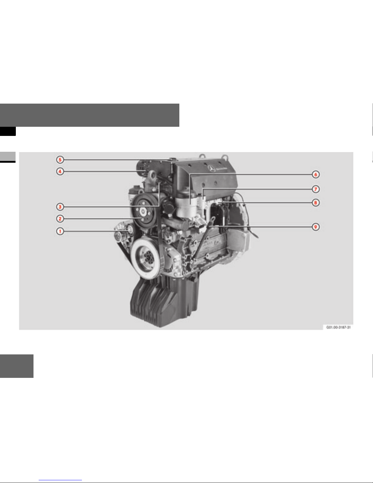
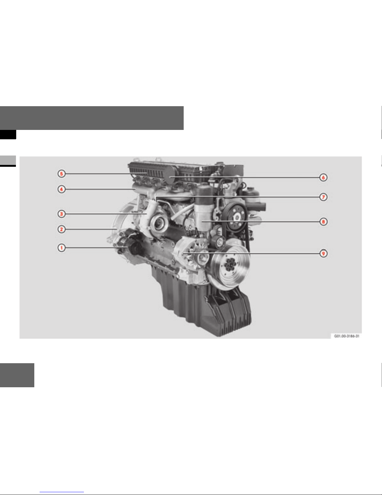
OM 904 LA overview
1

11
At a glance
OM 904 LA overview
1
1 Poly-V-belt tensioning pulley
2 Coolant pump
3 Coolant line heater supply*
4 Crankcase breather
5 Oil filler opening
6 Fuel filter
7 Fuel prefilter
8 MR (engine control) unit
9 Dipstick
12
At a glance
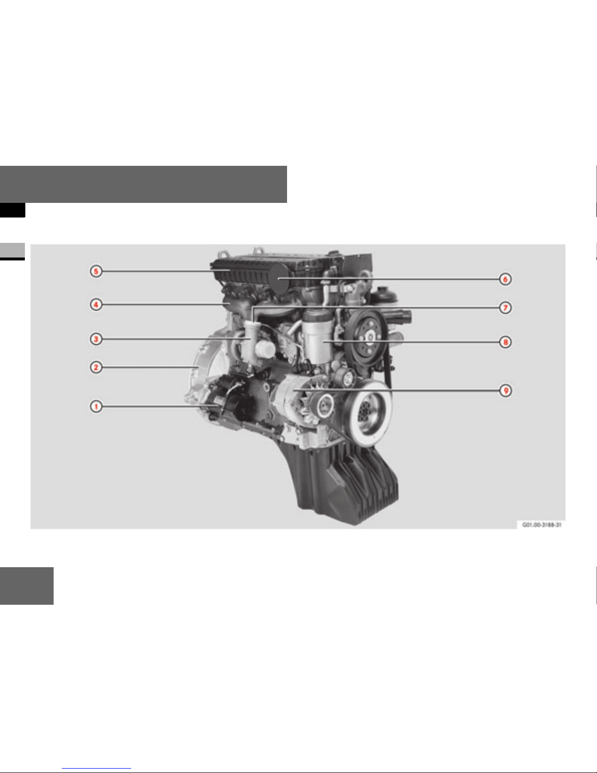
OM 904 LA overview
1

13
At a glance
OM 904 LA overview
1
1 Starter motor
2 Flywheel housing
3 Exhaust gas turbocharger
4 Exhaust manifold
5 Charge-air housing
6 Charge-air pipe connection from the
intercooler
7 Charge-air pipe connection to the
intercooler
8 Oil filter
9 Alternator
14
At a glance
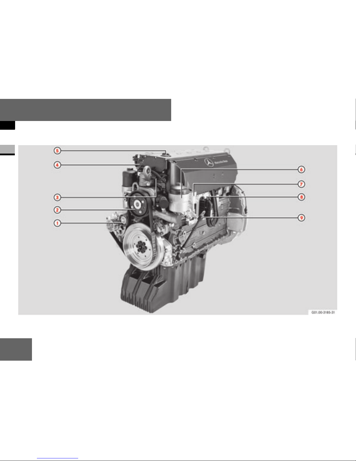
OM 906 LA/OM 926 LA overview
1

15
At a glance
OM 906 LA/OM 926 LA overview
1
1 Poly-V-belt tensioning pulley
2 Coolant pump
3 Coolant line heater supply*
4 Crankcase breather
5 Oil filler opening
6 Fuel filter
7 Fuel prefilter
8 MR (engine control) unit
9 Dipstick
16
At a glance
OM 906 LA/OM 926 LA overview
1

17
At a glance
OM 906 LA/OM 926 LA overview
1
1 Starter motor
2 Flywheel housing
3 Turbocharger with wastegate valve
4 Exhaust manifold
5 Charge-air housing
6 Charge-air pipe connection from the
intercooler
7 Charge-air pipe connection to the
intercooler
8 Oil filter
9 Alternator
18
At a glance
Location of sensors
1
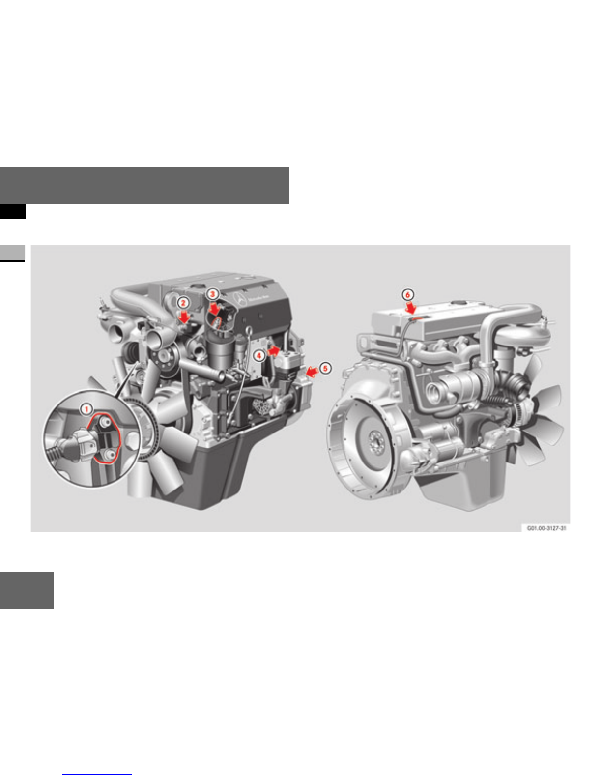
OM 904 LA (OM 906 LA/OM 926 LA
comparable)

19
At a glance
Location of sensors
1
1 Combined oil temperature/pressure
sensor
2 Coolant temperature sensor
3 Fuel temperature sensor
4 TDC sensor (on the camshaft sprocket)
5 Crankshaft position sensor (on the
flywheel)
6 Combined charge-air pressure/
temperature sensor
20
At a glance
Engine number
1
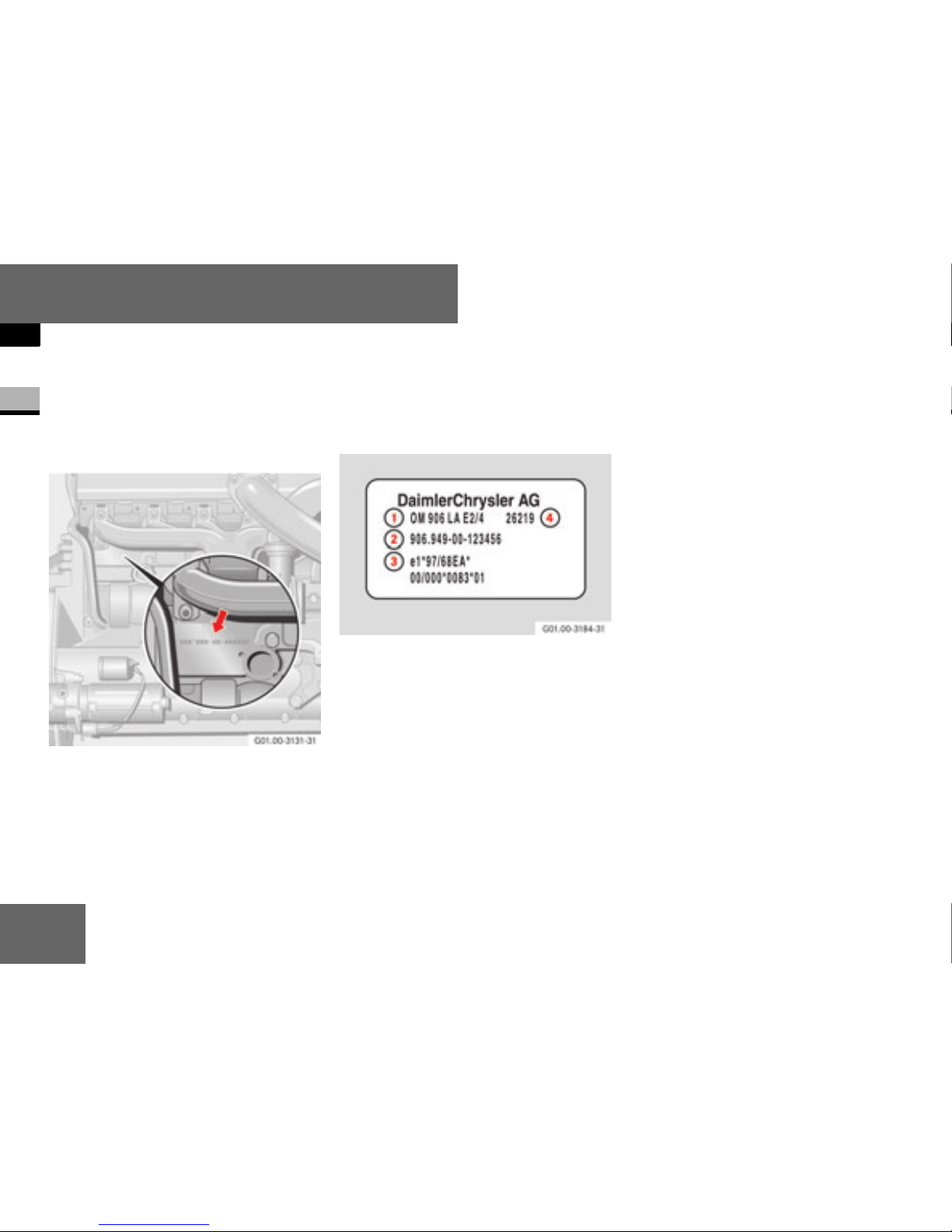
Location
The engine number is located on the rear
right-hand side, beneath the exhaust manifold (arrow).
Location of the engine number on the righthand side of the engine
Information on the engine
As well as the name of the manufacturer,
the following data is listed:
Information on the engine
1 Engine model designation
2 Engine number
3 Type approval number
4 Engine group

21
2
Before commissioning
General information
Transport and installation

22
Before commissioning
General information
2
The engine data card (A4 sheet) forms an
integral part of the documents belonging
to the engine and should always be kept
with the Maintenance Booklet. It contains
details about the engine, including special
equipment.
The engine data card must be produced for
the procurement of genuine parts.
Engine data card
Type designation
OM 9XX L A
OM Oil engine
(diesel engine)
9XX Engine model
L Intercooler
A Exhaust gas
turbocharger
Engine data card
i
The engine data card describes the
scope of delivery from the
DaimlerChrysler factory; later changes
to the scope of delivery are not recorded on the data card.
Always keep the engine data card with
the Maintenance Booklet.

23
Before commissioning
General information
2
The OM 904 LA (four cylinder) and
OM 906 LA/OM 926 LA (six cylinder) engines are water-cooled 4-stroke direct injection diesel engines.
The cylinders are arranged in-line. Each
cylinder has two inlet valves and one outlet
valve.
Each cylinder has a separate fuel-injection
pump (unit pump) with a short high-pressure fuel injection line to the multi-hole
nozzle located in the centre of the combustion chamber. The unit pumps are mounted directly on the crankcase and driven by
the camshaft.
The engines are fitted with a turbocharger
and intercooler as standard. The engine
can be equipped with an engine brake* as
an option (throttle valve and constantlyopen throttle valves*).
The engines produce particularly low emissions. Injection start, injection period and
injection quantity are controlled fully electronically.
The control system consists of an engine
control unit mounted on the engine, the
MR (engine control) module and the application-dependent FR (drive control) unit or
the ADM adaptation module. All these control units are interconnected via the Controller Area Network (CAN).
Description of the engine

24
Before commissioning
General information
2
To increase the braking power, the engine
can be equipped with an exhaust brake
valve on the exhaust gas turbocharger in
conjunction with constantly-open throttle
valves on the cylinders.
Whereas exhaust gas backpressure, acting
through the exhaust brake valves, can be
used to increase the braking power, the
constantly-open throttle valves cause a
reduction of compression in the power
stroke (3rd stroke), leaving compression
(2nd stroke) practically unaffected.
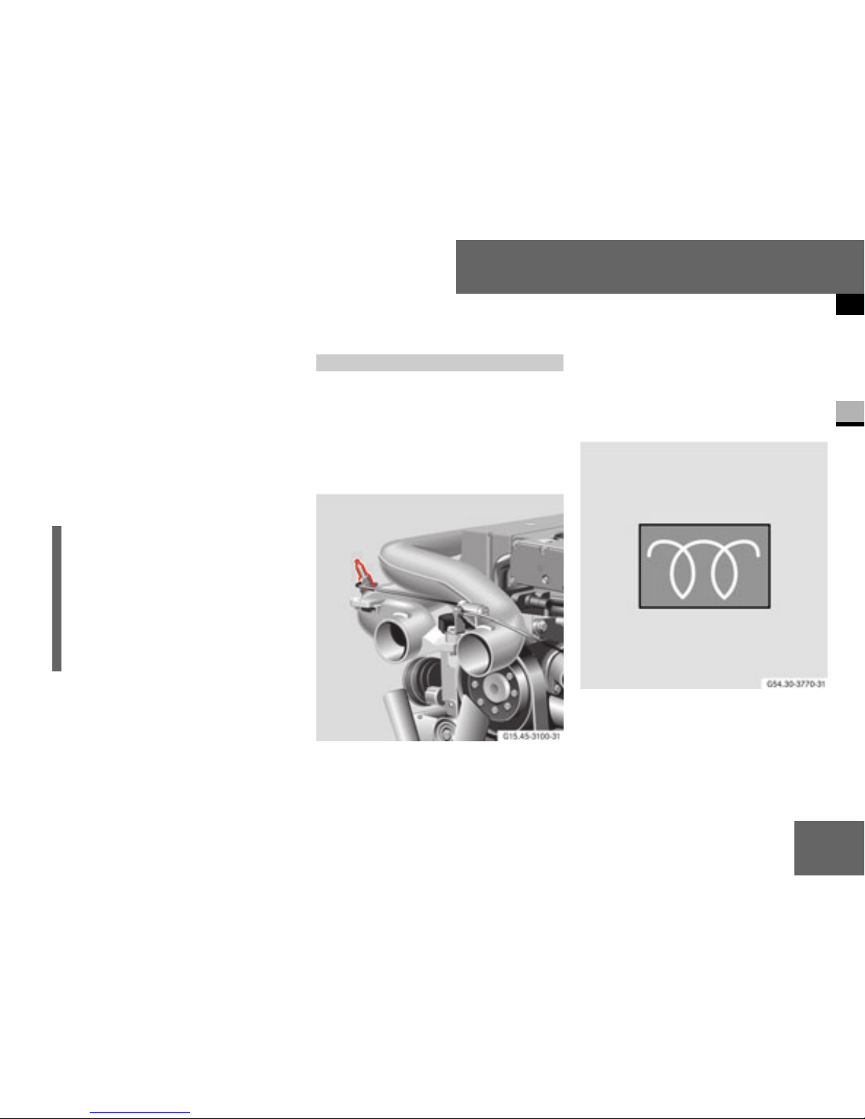
The constantly-open throttle valves are
valves in the cylinder head. When open,
they connect the combustion chamber to
the exhaust duct, which generates the required decompression in the power stroke.
Constantly-open throttle valves on the
4-cylinder engine
When the engine brake is engaged, the
constantly-open throttle valves are opened
pneumatically on the 4-cylinder engine and
hydraulically on the 6-cylinder engine. At
the same time, the exhaust brake valve on
the exhaust gas turbocharger is closed.
Engine brake*/constantly-open
throttle valves*
i
Hydraulic constantly-open throttle
valves
The constantly-open throttle valves are
not actuated in the lower engine speed
range between 900 and 1,300 rpm or if
the engine oil temperature is less than
40 °C.
Observe these restrictions during operation.
25
Before commissioning
General information
2
The engine brake is controlled by the FR
(drive control) unit ( page 29) or the
ADM.
The engine brake always remains deactivated at engine speeds of below 900 rpm
to prevent the engine from stalling. The engine brake is also automatically deactivated if the position sensor is triggered (e.g. if
the accelerator pedal is depressed).
The flame-start system is a cold-start aid
for when ambient temperatures are low. It
reduces the emissions of white smoke
once the engine has been started. The
starter motor and battery are also protected as a result of the shorter start-up time.
Flame-start system
A flame glow plug is fitted in the charge
pressure pipe of the intercooler. Fuel can
be ignited at this flame glow plug. The fuel
is supplied to the flame glow plug via a solenoid valve with a dosing nozzle.
Flame-start system indicator lamp
(example)
i
In the emergency running program
(constant engine speed), the engine
brake can only be activated in overrun
mode at an increased engine speed.
The engine brake is automatically deactivated again once a constant engine
speed has been reached.
Flame-start system*
26
Before commissioning
General information
2
Following the preglow time, which is dependent on the ambient temperature
(maximum 20 seconds), the flame-start
system is activated and the flame-start
system indicator lamp goes out.
Once the engine has been started, the
flame-start system is supplied with fuel by
the fuel pump.
The flame-start system is only enabled if
the engine is started within 30 seconds of
the flame-start system indicator lamp going out.
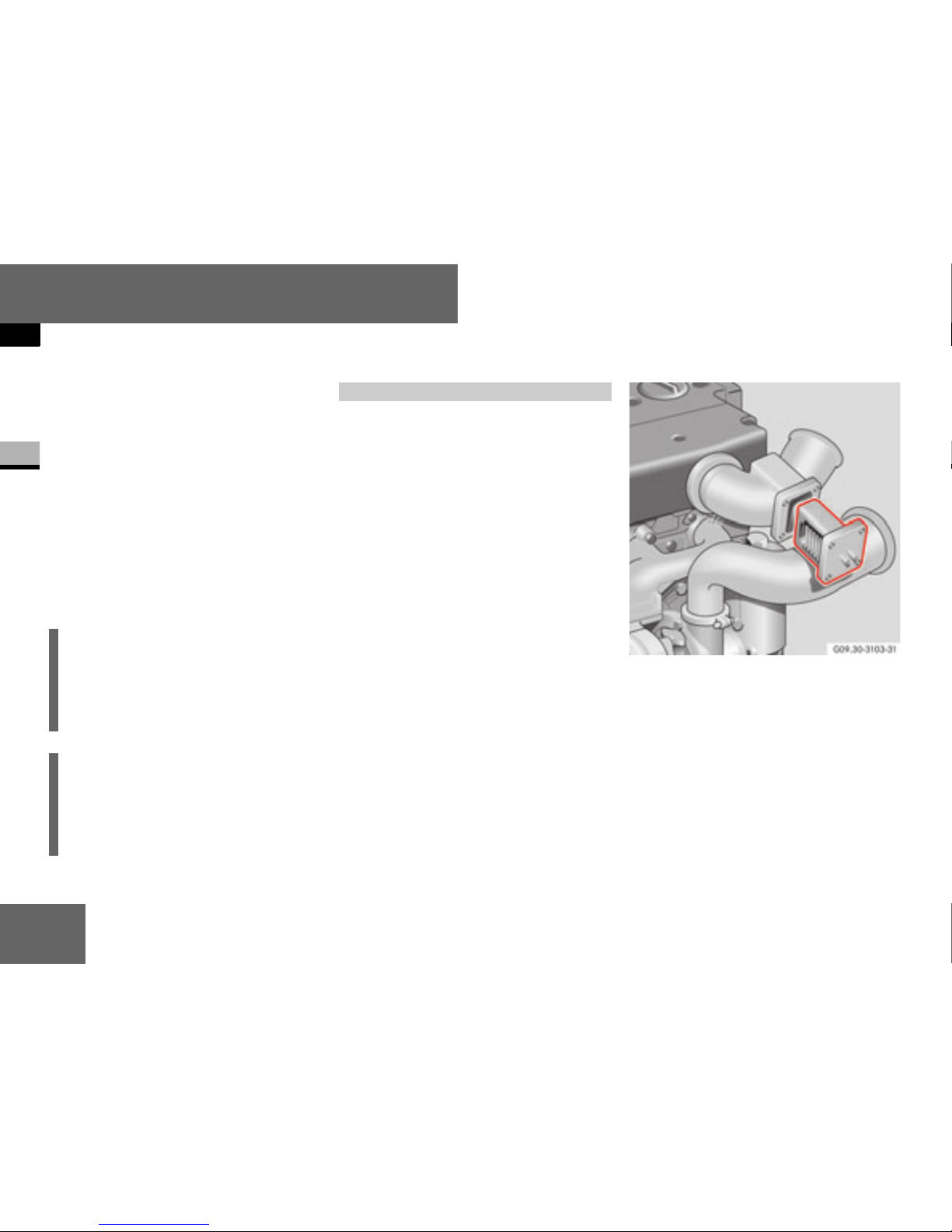
The grid heater is a cold-start aid for low
ambient temperatures. A heating strip integrated in the intercooler charge pressure
pipe preheats the charge air. The starter
motor and battery are also protected as a
result of the shorter start-up time.
The tendency of the engine to emit white
smoke after it has been started is reduced
by a subsequent heating time of up to
180 seconds.
Grid heater
i
If the flame-start system indicator lamp
does not go out after more than 20 seconds, there is a malfunction in the
flame-start system.
i
For operation at low ambient temperatures, see also the “Diesel fuels”
( page 59) and “Coolant”
( page 64) sections.
Grid heater*

27
Before commissioning
General information
2
The engine has a fully electronic control
system, which, in addition to the engine
and associated sensors, also comprises:
an MR (engine control) unit and
an FR (drive control) unit and/or other
vehicle-specific control units, e.g. ADM
Both are interconnected via a CAN (Controller Area Network) line, on which all the
necessary data/information is exchanged.
The engine control monitors itself as well
as the engine. A safety and emergency running program is selected automatically,
depending on the malfunctions/system
failures that occur ( page 37).
MR (engine control) unit (mounted on
the engine)
The MR (engine control) unit is mounted on
the left-hand side of the engine.
MR (engine control) unit
The MR (engine control) unit processes
data from the drive control unit or the
ADM, indicating for example the position
of the position sensor (accelerator pedal),
the engine brake* or engine start/stop,
etc.
Telligent® engine system
 Loading...