


 Loading...
smart Wallbox Home
>> Installation manual for specialist electrical contractors.

Important addresses.
Contact Mercedes-Benz AG
Mercedesstraße 120
70372 Stuttgart, Germany
For technical issues, please contact your local smart technical support.
This manual, in its entirety or in parts, must not be reproduced, stored electronically or otherwise transmitted electronically, electrically, mechanically, optically, chemically, by photocopy or as an audio recording without express written permission.
Version 1.2, smart-IM_Home-2020-01-15 |
Article No.: 0301712 |

Contents.
ii Important addresses.
|
01 |
1 |
Important information. |
1 |
Preface. |
1 |
Notes on this manual. |
1Safety notices in this manual.
2Safety notices on the device.
2General safety information.
3General product information.
4Notes regarding installation.
02
5 Introducing the product.
5Unpacking and components included.
5Identifying your model variant.
6Structure of the smart Wallbox Home.
03
10 Preparations, installation and taking into operation.
10 General requirements of the installation site.
10 Requirements for the power supply cable.
12 Mechanical and electrical installation.
16Taking the Wallbox into operation.
17Setup and test modes.
04
20 Error detection and solutions.
20Operational malfunctions and solutions.
21Error codes and solutions.
24 Checking the internal RCCB.
24Taking the product out of and back into operation.
25Returning your Wallbox.
05
26 Appendix.
26Technical specifications.
27Scale drawings and dimensions.
28Wiring sequence Type 2.
28Guidelines & Norms.
29CE certification and compliance declaration.
29Glossary & Definitions.
29Trademarks.
30Intellectual Property & Copyright.
30 Disposal advice.
32 Mains Connection Schemes.


smart Wallbox Important information 1
‡ Important information.
Preface.
This manual describes the mechanical and electrical installation of the smart Wallbox Home. The working steps described in this manual must only be carried out by qualified specialist personnel (mechanical installation) and qualified specialist electrical contractors (electrical installation), who, on the basis of their specialist training, knowledge and experience as well as their knowledge of the relevant regulations, can assess and carry out the working steps described in this installation manual and recognize potential hazards.
The smart Wallbox Home model variants can be clearly identified by the product label: These labels state the smart product identification number (exterior underside) as well as the ABL model number (inside of interior electronic components cover), but are identical with regards to technical specifications. Always make sure before installation that your model variant is the one described in this installation manual!
The following Wallbox model variants are described in this manual:
smart product |
ABL model number |
|
identification number |
||
|
||
A0009066308 |
2W22S1 |
|
A0009066008 |
2W72S9 |
Notes on this manual.
This manual documents the steps and settings required for installing the smart Wallbox Home, for taking it into and out of operation, and for resolving malfunctions during operation. For quick and easy reference, certain sections of this manual are specially formatted.
>Descriptions listing equally valid options (as is the case here) are indicated by bullet points.
>Descriptions that describe performing a function are shown in the form of numerical lists indicating the order of the individual working steps.
Please make sure you read this manual carefully and ensure in particular that you follow all safety notices given in this manual.
All dimensions in this manual are in millimeters. Where necessary, the scale is indicated for each illustration.
Please note that all technical details, specifications and design characteristics of the product may be changed without prior notice.
Safety notices in this manual.
In particular, the warnings and safety measures in this manual that are marked as follows must be adhered to. The symbols carry the following meanings:

DANGER!
Sections marked with this symbol draw attention to electrical voltages that represent a danger to life and limb: Actions contrary to these safety notices may lead to severe or fatal injury. Actions marked with this symbol must not be carried out under any circumstances.
CAUTION!
Sections marked with this symbol draw attention to further hazards that may lead to damage to the Wallbox itself or to other electric devices. Actions marked with this symbol must be carried out with special care.
PLEASE NOTE!
Sections marked with this symbol draw attention to further important information and special features that are necessary for the reliable operation of the device. Actions marked with this symbol should be carried out as required.
Safety notices on the device.
Further operational and safety notices are provided on the labels on the right hand side and underside of the housing, as well as on the electronic components cover inside the Wallbox. These symbols carry the following meanings:
WARNING!
Please ensure that you first read the operating manual included with the smart Wallbox Home, especially before you remove the housing cover of your Wallbox.
 WARNING!
Please ensure that you first read the installation manual (this document) before you remove the electronic components cover inside the Wallbox.
DANGER!
After opening the housing, dangerous voltages may be present on the inside of the Wallbox as well as on components you are able to touch.
General safety information.
Please pay attention to the following points:
>Read this manual carefully.
>Heed all warnings.
>Follow all instructions.
>The smart Wallbox Home is available with a range of country-specific specifications. Please use the identification on the product label located on the underside of the Wallbox to check whether the Wallbox is approved to be installed and operated in your country.
>The Wallbox must be installed, connected and approved for operation according to local rules and regulations by a qualified specialist electrical contractor.

smart Wallbox Important information 3
>The smart Wallbox Home has an internal Type A residual current circuit breaker (RCCB, see also „Glossary & Definitions.“ on page 29). In addition, the Wallbox variants described in this manual also feature integrated DC fault current detection to ensure maximum safety during operation. However, countryspecific and local regulations must always be observed. These may prescribe an RCCB with a different tripping type (e.g. Type B).
>Please ensure that minimum clearances of 50 cm are kept on all sides of the Wallbox during and after installation.
>Only use accessories intended and sold for the device by smart.
>Do not install this Wallbox in close vicinity to running water or water jets: The smart Wallbox Home is protected against water entering the device according to IP 55.
>The smart Wallbox Home must not be installed in areas subject to flooding.
>The smart Wallbox Home must not be installed in explosive atmosphere areas (EX areas).
>The smart Wallbox Home must not be covered with stickers or other objects or materials to ensure sufficient air circulation at all times.
>No liquids, objects or receptacles containing liquids must be placed on the housing.
>Please note that additional overvoltage protection may be required depending on the connected vehicle and/or national regulations.
>Please note that the fixed charging cable of the smart Wallbox Home must not be extended with connectors, adapter cables or in any other way during operation.
>Please note that operating a radio transmitter in the immediate vicinity (< 20 cm) of the Wallbox may lead to malfunctions and should therefore be avoided.
>This device is not intended to be used by persons with limited physical, sensory or mental abilities (including children) and/or who lack knowledge, unless they are supervised by someone responsible for their safety or have received instructions from such a person on how to use the device.
>Children must be supervised so that they do not play with the device.
>Please note that the smart Wallbox Home may be installed and operated at elevations of max. 2,000 meters AMSL (above mean sea level).
General product information.
This smart Wallbox Home represents the current state of technology and complies with all current technical safety requirements, guidelines and standards. The safety notices in this manual serve to ensure the proper and safe installation as well as subsequent operation of the device. Disregard of or actions contrary to the safety information and instructions contained in this manual may lead to electric shock, fire, severe or fatal injury.
The smart Wallbox Home must be installed by a qualified specialist electrical contractor, connected according to local regulations and provisions, and subsequently checked and approved for operation.
Malfunctions affecting the safety of persons, connected vehicles or the device itself must be repaired by an authorized specialist electrical contractor only.

Should a malfunction occur with your Wallbox, please first read the sections regarding „Error detection and solutions.“ on page 20. Should the fault or malfunction recur and still not be able to be resolved, please contact your local smart technical support.
Have the Wallbox taken out of operation and replaced by a qualified specialist electrical contractor or contact your local smart technical support if:
>the housing has been damaged mechanically,
>the housing cover has been removed or can no longer be fixed to the housing,
>it becomes obvious that sufficient protection against water and/or foreign objects entering the device is no longer possible,
>there is functional or visible damage to the fixed charging cable,
>or the Wallbox does not function properly or has been otherwise damaged.
DANGER!
Should you detect damage to the housing or charging cable, you must immediately discontinue installation or take the already installed Wallbox out of operation via the upstream miniature circuit breaker (in the following called MCB, see also „Glossary & Definitions.“ on page 29) in your domestic power supply and the internal RCCB: No further use of the Wallbox is permitted in this case! Replace the Wallbox or contact your local smart technical support!
Notes regarding installation.
Please observe the following instructions for the installation of your smart Wallbox Home:
>The device must always be connected to the protective earth conductor of your electricity supply. The protective earth connection will be made and checked by the installing contractor. After installation, only qualified specialist electrical contractors may make changes.
>At all times comply with local safety regulations for the country in which you operate the Wallbox.
>For proper operation, the power supply for the smart Wallbox Home must be protected in the domestic power supply with an MCB (rated current depending on power supply and Wallbox settings, but no more than 32 A) that is not followed by any other downstream electrical devices. Please always observe the applicable national requirements regarding the selection of the MCB.
>To disconnect the Wallbox completely from the electricity grid, the power supply must be interrupted using the upstream MCB and the internal RCCB.
>Ensure that the rated voltage and rated current of the device comply with the parameters of your local electricity grid and that the rated output is not exceeded during the charging procedure.
>The Wallbox should not be installed in areas of high pedestrian traffic. Installation along thoroughfares and marked escape routes should be especially avoided.
>Never install the Wallbox in a confined space. In particular, you must ensure that the vehicle can be parked at a suitable distance from the Wallbox for charging, and connected without any strain on the charging cable. The distance between vehicle and Wallbox should be at least 50 cm and no more than 5 m.
>You must not under any circumstances make any changes to the housing or the internal wiring of the Wallbox. Any disregard of this instruction represents a safety risk, fundamentally breaches the guarantee provisions and may void the warranty with immediate effect.

smart Wallbox Introducing the product 5
‡ Introducing the product.
The smart Wallbox Home is entirely manufactured in Germany and at all times complies with the regulations and norms for the charging of electric vehicles applicable throughout Europe according to IEC 61851-1, Mode 3 – please also refer to the section on „Guidelines & Norms.“ on page 28. According to their requirements, users may select from model variants with a range of charging outputs and fixed charging cable with Type 2 charging plug, which are designed for domestic and semi-public applications.
We place the highest value on user safety in all our products. For this purpose, your Wallbox features an internal Type A RCCB and integrated DC fault current detection, which, in combination with the protective measures of your domestic power supply and of your electric vehicle, effectively protects from short circuit, electric shock and other operational hazards.
The Wallbox is especially easy to operate during everyday use: A multi-colored LED display in the lower part of the housing cover allows you to check the current operating status at any time. Should a malfunction occur, you can identify the cause by the specific error code displayed by the multi-colored LED without having to open the housing of the Wallbox. After being taken into operation by a specialist contractor, the smart Wallbox Home is ready for charging at any time, while each charging process must be separately authorized via the integrated key switch.
Unpacking and components included.
The smart Wallbox Home package includes a range of accessory components needed for installation and proper operation. Therefore, please check immediately after unpacking whether the following components are included:
Component |
Quantity Description |
|
|
Charging station consisting of housing base with integraWallbox 1 ted electronic unit, internal electronic components cover and
housing cover
smart Wallbox Home
|
|
Quick start |
1 |
Quick start guide including safety notices in printed form |
|
|
|||
|
|
guide |
||
|
|
|
|
|
|
|
|
|
|
|
|
|
|
|
Set of fixings for wall mounting, consisting of 2 x 4 chipboard
Installation kit 1 screws as well as matching wall plugs, keys for key switch (2 pcs.), keys for locking the housing cover (2 pcs.), drilling tem-
plate
Should one or more of the components listed above be missing after unpacking, please contact the point of sale where you purchased the Wallbox.
Identifying your model variant.
The smart Wallbox Home is available in a range of model variants that are mechanically and electrically tailored to different application profiles.

The product label with the specific smart product identification number |
|
|
|
|||||||||||
|
|
|
||||||||||||
for the Wallbox is located on the underside of the Wallbox. For identifi- |
A 000 906 63 08 / 001 |
|
||||||||||||
cation, the model code (A 000 906 XX XX) as well as the power supply ra- |
|
|||||||||||||
Produced by: ABL SURSUM Bayerische Elektrozubehör GmbH & Co. KG, |
|
|||||||||||||
tings (voltage, frequency, current) indicated below it are especially rele- |
Albert-Büttner-Straße 11, 91207 Lauf / Pegnitz, Germany |
|
||||||||||||
Produced for: Mercedes-Benz AG, |
|
|
||||||||||||
vant. When you open the housing cover for installation, you will find an |
Mercedesstr. 120, 70372 Stuttgart, Germany |
|
|
|||||||||||
|
2W22S100001 |
|
||||||||||||
|
|
|
|
|
|
|
|
|
additional product information label on |
|
2018-05-30 |
|
||
|
|
|
|
|
|
|
|
|
~220-240V 50Hz 32A |
IP55 3Ph |
|
|||
|
|
|
|
2W22S100001 |
|
the inside of the RCCB access flap, |
~380-415V |
-30°C to 50°C |
|
|||||
|
|
|
|
|
|
|
|
|||||||
|
|
|
|
|
which will also show the ABL model |
|
|
|
||||||
|
|
|
|
|
|
|
|
|
number. Using the smart product identification number or the ABL model |
|||||
|
|
|
|
|
|
|
|
|
number, please always ensure before installation that your Wallbox mo- |
|||||
|
|
|
|
|
|
|
|
|
||||||
|
|
|
|
|
|
|
|
|
del variant is the one whose installation is described in this document. |
|||||
|
|
|
|
|
|
|
|
|
||||||
|
|
|
|
|
|
|
|
|
||||||
|
|
|
|
|
|
|
|
|
||||||
|
|
|
|
|
|
|
|
|
You can find a list of the Wallbox model variants described in this ma- |
|||||
|
|
|
|
|
|
|
|
|
||||||
|
|
|
|
|
|
|
|
|
nual and the correlations between smart product identification numbers |
|||||
|
|
|
|
|
|
|
|
|
||||||
|
|
|
|
|
|
|
|
|
||||||
|
|
|
|
|
|
|
|
|
||||||
and ABL model numbers in the table below. |
|
|
|
|
||||||||||
smart product |
ABL model |
Grid connection |
Model variant |
|
|
|
||||||||
identification number |
number |
|
|
|
|
|||||||||
|
|
|
|
|
|
|||||||||
|
|
|
|
|
|
|
|
|
|
|
|
|
|
|
A0009066308 |
2W22S1 |
|
230 / 400 V 50 Hz |
Fixed charging cable according to IEC 62196- |
||||||||||
|
1 or 3 x 32 A |
2 Type 2, ca. 6 m; charging output 22 kW |
||||||||||||
|
|
|
|
|
|
|
|
|
|
|||||
A0009066008 |
2W72S9 |
|
230 V 50 Hz |
Fixed charging cable according to IEC 62196- |
||||||||||
|
1 x 32 A |
2 Type 2, ca. 6 m; charging output 7.2 kW |
||||||||||||
|
|
|
|
|
|
|
|
|
|
|||||
CAUTION!
The information and technical specifications contained in this manual relate exclusively to the model variants listed in this manual and must not be transferred to other Wallbox models: These variants include specific instruction manuals where necessary.
Should your Wallbox model variant not be described in this manual, please contact your local smart technical support: Do not under any circumstances install the Wallbox in this case, as this could lead to damage to the Wallbox, and to potentially fatal injury.
Structure of the smart Wallbox Home.
The smart Wallbox Home consists of the following:
1 2 3
smart Wallbox Introducing the product 7
1 Housing cover
Detachable outer plastic cover to be fixed to the housing base using hanging lip (upper edge) and locked using lockable screw (lower edge)
2 Electronic components cover
Internal cover for electronic module with integrated flap for manual access to the RCCB (residual current circuit breaker).
3 Housing base
Base with integrated electronic module, fixed charging cable with Type 2 charging plug and charging plug storage holder
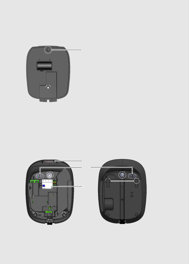
Housing cover (detail)
Front view |
Rear view |
4 
 5
5
6 

4 Plastic lip and guides
The plastic lip is for hanging the housing cover onto the housing base. The two guide pins ensure the correct vertical positioning of the housing cover.
5 LED zone
The multi-colored LED display is located in this part of the housing cover.
6 Locking slot
The locking slot is for locking the housing cover to the housing base using the lockable screw.
Electronic components cover (detail)
Front view
7
 8
8
 9
9
7 Opening for M4 fixing screw
This opening is used to fix the electronic components cover to the housing base with a fixing screw (M4 x 10).
8 RCCB (residual current circuit breaker) access flap
This flap provides access to the internal RCCB of the Wallbox.
9 Lens for multi-colored LED display
The multi-colored LED display is shown through this lens.
Housing base (detail) |
|
Front view |
Rear view |
0
Q
 W
W 
U 


E

 R
R
I 
 T
T
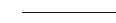
 O
O
 Y
Y
0 Housing cover slot
The plastic lip of the housing cover 4 is inserted into this slot.
Loading...