


OM 900
Powersystems • Industrial Engines
Maintenance and Repair
Series 457, 500 and 900
Advanced Training
As at 04/03
Powersystems • Industrial Engines
Maintenance and Repair Series 457,

This document is provided for training purposes only and is not subject to the normal updates.
Printed in Germany
ã 2003 Copyright DaimlerChrysler AG
Herausgeber: Global Training
This documentation and all its constituent parts are subject to copyright. Any reproduction or re-
use requires written permission from DaimlerChrysler AG in advance. This especially applies to
any duplication, dissemination, editing, translation, and microfilming of this documentation, or
storage and/or processing on electronic systems, databases and online services.
Note:
The term "employee" always refers to both
male and female staff.
1511 1209 02 - 1
st
edition 04.03 236 As at 04/03

05/03 Powersystems • Industrial Engines Maintenance and Repair Series 457, 500 and 900 Advanced Training
Content
I1
Content 07.05.2003
Title Side
Welcome ..................................................................................................................................................................................................................................................1
Engine model series OM 457 LA..............................................................................................................................................................................................................2
Engine OM 457 LA ...................................................................................................................................................................................................................................4
Series 457<>Cylinder head....................................................................................................................................................................................................................11
Series 457<>Cylinder head - cross section (transverse and longitudinal) ............................................................................................................................................12
Series 457 LA<>Port assignments in the cylinder head gasket ............................................................................................................................................................13
Series 457<>Cylinder head bolts - tightening instructions....................................................................................................................................................................14
Series 457<>Setting valve play .............................................................................................................................................................................................................16
Series 457<>Removing/installing the nozzle holder combination........................................................................................................................................................19
Series 457<>Valve cover and valve cover gasket .................................................................................................................................................................................25
Series 457<>Oil pan ..............................................................................................................................................................................................................................26
Series 457<>Pump-line-nozzle injection system ...................................................................................................................................................................................27
Series 457<>Removing/installing the MR/PLD unit pump...................................................................................................................................................................28
Series 457<>Pistons..............................................................................................................................................................................................................................35
Series 457<>Lubrication schematic diagram ........................................................................................................................................................................................36
Series 457<>Oil spray nozzle.................................................................................................................................................................................................................38
Series 457<>Crankcase and cylinder liner ............................................................................................................................................................................................39
Series 457<>Camshaft ..........................................................................................................................................................................................................................40

05/03 Powersystems • Industrial Engines Maintenance and Repair Series 457, 500 and 900 Advanced Training
Content
I2
Series 457<>Fuel system ......................................................................................................................................................................................................................42
Series 457<>Fuel pump.........................................................................................................................................................................................................................45
Series 457<>Fuel prefilter with heated water separator .......................................................................................................................................................................46
Series 457<>Planetary drive starter ......................................................................................................................................................................................................48
Series 457<>Fan drive and fan systems................................................................................................................................................................................................50
Series 457<>Air compressor .................................................................................................................................................................................................................52
Series 457<>Turbocharger BR S400 .....................................................................................................................................................................................................53
Series 457<>Engine oil and filter change ..............................................................................................................................................................................................54
Series 457<>Replacing the fuel filter ....................................................................................................................................................................................................56
Series 457<>Fuel filter with water separator - replacing the filter element..........................................................................................................................................58
Series 457<>Air cleaner, engine coolant service ..................................................................................................................................................................................60
Series 500<>Engine models ..................................................................................................................................................................................................................62
Series 500<>Technical features ............................................................................................................................................................................................................64
Series 500<>Cylinder head - port assignment ......................................................................................................................................................................................70
Series 500<>Cylinder head....................................................................................................................................................................................................................71
Series 500<>Cylinder head mounting ...................................................................................................................................................................................................73
Series 500<>Cylinder head gasket ........................................................................................................................................................................................................74
Series 500<>EURO 2 and EURO 3 cylinder heads compared ...............................................................................................................................................................75
Series 500<>Valve assembly.................................................................................................................................................................................................................77
Series 500<>Pump-line-nozzle injection system (PLD) .........................................................................................................................................................................83
Series 500<>Removing/installing the MR/PLD unit pump...................................................................................................................................................................91
Series 500<>EURO 2 and EURO 3 pistons ......................................................................................................................................................................................... 101

05/03 Powersystems • Industrial Engines Maintenance and Repair Series 457, 500 and 900 Advanced Training
Content
I3
Series 500<>Connecting rod .............................................................................................................................................................................................................. 102
Series 500<>Crankcase...................................................................................................................................................................................................................... 103
Series 500<>Cylinder liners................................................................................................................................................................................................................ 104
Series 500<>EURO 2 and EURO 3 cylinder liners compared ............................................................................................................................................................. 107
Series 500<>Crankcase ventilation system ....................................................................................................................................................................................... 108
Series 500<>Fuel system ................................................................................................................................................................................................................... 112
Series 500<>Oil cooler and oil filter housing – component locations................................................................................................................................................ 124
Series 500<>Oil circuit ....................................................................................................................................................................................................................... 128
Series 500<>Engine oil system........................................................................................................................................................................................................... 129
Series 500<>Oil spray nozzle.............................................................................................................................................................................................................. 130
Series 500<>Water guide ................................................................................................................................................................................................................... 134
Series 500<>Thermostat location....................................................................................................................................................................................................... 136
Series 500<>Supercharging system and charge air ducting .............................................................................................................................................................. 137
Series 500<>Engine oil and filter change ........................................................................................................................................................................................... 140
Series 500<>Cleaning the fuel prefilter / filter insert ........................................................................................................................................................................ 144
Series 500<>-Fuel prefilter with water separator - replacing the filter element ................................................................................................................................ 146
Series 500<>Replacing the oil separator insert ................................................................................................................................................................................. 148
Series 500<>Replacing the fuel filter - air cleaner - coolant .............................................................................................................................................................. 150
Engines OM 904 and 906 ................................................................................................................................................................................................................... 152
Engine series 900 ............................................................................................................................................................................................................................... 153
Series 900<>Technical features ......................................................................................................................................................................................................... 156
Series 900<>Port assignments in the cylinder head gasket .............................................................................................................................................................. 159

05/03 Powersystems • Industrial Engines Maintenance and Repair Series 457, 500 and 900 Advanced Training
Content
I4
Series 900<>Tightening instructions for cylinder head bolts ............................................................................................................................................................. 160
Series 900<>Valve control.................................................................................................................................................................................................................. 162
Series 900<>Setting valve play .......................................................................................................................................................................................................... 164
Series 900<>Pump-line-nozzle injection system (PLD) ...................................................................................................................................................................... 167
Series 900<>Crankcase...................................................................................................................................................................................................................... 185
Series 900<>Ölspritzdüsen - Unterschiede ........................................................................................................................................................................................ 188
Series 900<>Pistons and piston rings ................................................................................................................................................................................................ 189
Series 900<>Connecting rod .............................................................................................................................................................................................................. 190
Series 900<>Pistons and connecting rod - modifications .................................................................................................................................................................. 191
Series 900<>Engine oil circuit ............................................................................................................................................................................................................ 192
Series 900<>Removing/installing the oil pan .................................................................................................................................................................................... 196
Series 900<>Fuel system ................................................................................................................................................................................................................... 200
Series 900<>Supercharging system and charge air ducting .............................................................................................................................................................. 212
Series 900<>Removing/installing the coolant thermostatic control ................................................................................................................................................. 216
Series 900<>Engine oil and filter change ........................................................................................................................................................................................... 218
Series 900<>Cleaning the fuel prefilter - filter insert ......................................................................................................................................................................... 221
Series 900<>Fuel prefilter with water separator - replacing the filter element ................................................................................................................................. 223
Series 900<>Replacing the fuel filter - air cleaner - coolant .............................................................................................................................................................. 226
05/03 Powersystems • Industrial Engines Maintenance and Repair Series 457, 500 and 900 Advanced Training
Welcome
1
Welcome 07.05.2003
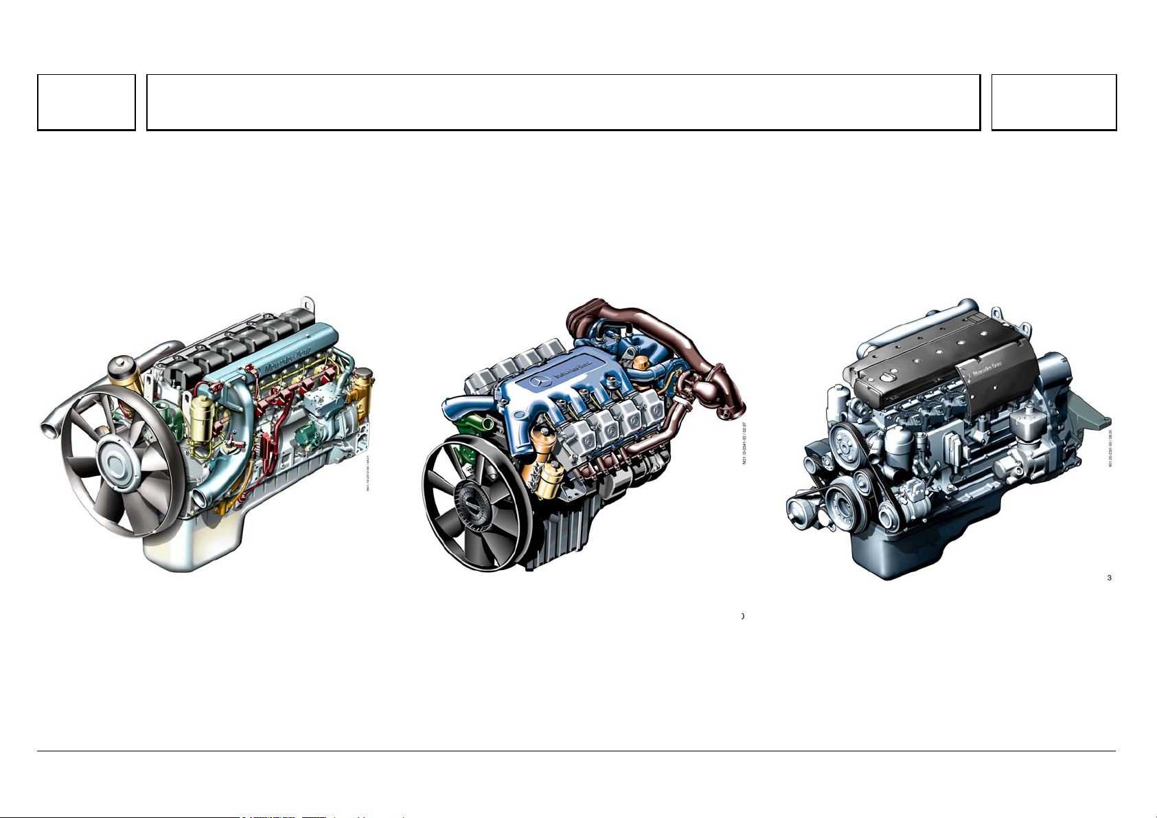
OM 457 LA OM 502 LA OM 906 LA
N01.10-2073-50 N01.10-0341-50 N01.00-2301-50
05/03 Powersystems • Industrial Engines Maintenance and Repair Series 457, 500 and 900 Advanced Training
Series 500<>Engine models
62
Series 500<>Engine models 07.05.2003
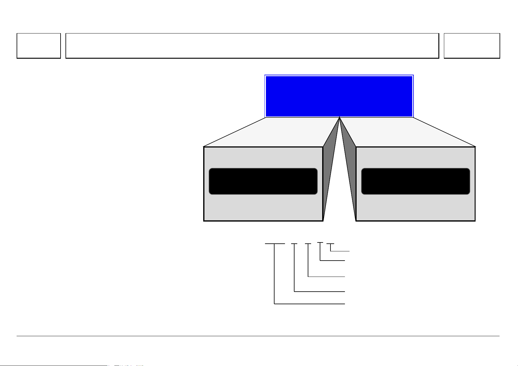
The 500 engine model series is future-ready, and
comes in V6 and V8 cylinder variants with 2 litre
swept volume per cylinder.
The sales designation is formed in the same way
as the 400 model series:
6-cylinder engine: OM 501 LA
8-cylinder engine: OM 502 LA
At the same time, the OM 457 LA engine was
developed with the same basic design as the V-
engines.
The Series 2000 V12 and V16 MTU engines are
derived from the BR 500, and are intended for
industrial applications.
Model series 500
V
6
OM 501 L
A
V
8
OM 502 L
A
V
H
= 12l V
H
= 16l
OM 501 LA
OM 501 LA
Turbocharger
Char
g
e air cooler
1=6-cylinder V-engine
2=8-cylinder V-engine
Model series 500
Diesel engine
05/03 Powersystems • Industrial Engines Maintenance and Repair Series 457, 500 and 900 Advanced Training
Series 500<>Engine models
63
N01.10-2026-11 N01.10-2028-11
The development of the 500 series encapsulates all the knowledge and experience gained from the 1 million V-engines manufactured since 1969, when
production of the OM 403 V10 engine began.

05/03 Powersystems • Industrial Engines Maintenance and Repair Series 457, 500 and 900 Advanced Training
Series 500<>Technical features
64
Series 500<>Technical features 07.05.2003
Þ Outstanding power output and torque characteristics over the whole
rpm range
Þ Dynamic start-off characteristics and pulling power
Þ Attractive power/weight ratio
Þ Low fuel consumption
Þ Enormous potential: the V6 engines meet the requirements of the highly
popular 400 HP Class
Þ High-pressure direct injection, pump-line-nozzle system with peak
pressures up to 1,800 bar.
Þ Electronic engine control (MR) with electronic system fixed to the
engine, and extensive engine protection functions
Þ Direct injection with centrally positioned 6-hole injection nozzle.
Þ 4-valve technology
Þ Useful engine brake rpm well over rated rpm, up to 2400 rpm
Þ Meets the emission legislation of EURO 3 and EUROMOT/EPA Level 2
Þ Turbocharger with charge air cooling
Þ V8 with 2 turbochargers
Þ Viscous fan clutch, electromagnetic fan clutch and high-speed fan
drive on the most powerful engines
Þ Rated engine speed 1,800 rpm or 2000 rpm
Þ Low maintenance requirement
Þ Long maintenance intervals
Þ Engine oil and fuel filter located at the front, for easy maintenance
Þ Maintenance-free belt drive
Þ Can run on FAME / RME (rape methyl ester) or biodiesel, and engine oil
changes are halved
Þ High reliability and long runtime
Þ Low number of component variants, as many parts are the same on both
6 and 8 cylinder engines
Þ Rear engine power take-off ex works

05/03 Powersystems • Industrial Engines Maintenance and Repair Series 457, 500 and 900 Advanced Training
Series 500<>Technical features
65

05/03 Powersystems • Industrial Engines Maintenance and Repair Series 457, 500 and 900 Advanced Training
Series 500<>Technical features
66
Overview of BR 500 engines with EURO 3 certification
Engine
model
No. of
cylinders/
layout
Output (rpm) Torque (rpm) Cylinder bore Cylinder
stroke
Displace
ment
Dimensions
L x W x H
Weight Power/weight
ratio
[kW/HP (at rpm)] [Nm (at rpm)] [mm] [mm] [l] [mm] [kg] [kg/kW]
OM 501 LA 6 Cyl./V 230/313 (1800) 1530 (1080) 130 150 11.95 1190x1020x1130 885 3.85
OM 501 LA 6 Cyl./V 260/354 (1800) 1730 (1080) 130 150 11.95 1190x1020x1130 885 3.40
OM 501 LA 6 Cyl./V 290/394 (1800) 1850 (1080) 130 150 11.95 1190x1020x1130 885 3.05
OM 501 LA 6 Cyl./V 300/408 (2000) 1900 (1080) 130 150 11.95 1190x1020x1130 885 2.95
OM 501 LA 6 Cyl./V 315/428 (1800) 2000 (1080) 130 150 11.95 1190x1020x1130 885 2.81
OM 502 LA 8 Cyl./V 320/435 (2000) 1900 (1080) 130 150 15.93 1530x1195x1080 1125 3.52
OM 502 LA 8 Cyl./V 350/476 (2000) 2100 (1080) 130 150 15.93 1530x1195x1080 1125 3.21
OM 502 LA 8 Cyl./V 350/476 (1800) 2300 (10809 130 150 15.93 1530x1195x1080 1125 3.21
OM 502 LA 8 Cyl./V 370/503 (2000) 2300 (1080) 130 150 15.93 1530x1195x1080 1125 3.04
OM 502 LA 8 Cyl./V 390/530 (1800) 2400 (1080) 130 150 15.93 1530x1195x1080 1125 2.88
OM 502 LA 8 Cyl./V 420/571 (1800) 2700 (1080) 130 150 15.93 1530x1195x1080 1125 2.68

05/03 Powersystems • Industrial Engines Maintenance and Repair Series 457, 500 and 900 Advanced Training
Series 500<>Technical features
67
Overview of BR 500 engines with EUROMOT/EPA Level 2 certification
Engine
model
No. of
cylinders/
layout
Output (rpm) Torque (rpm) Cylinder bore Cylinder
stroke
Displace
ment
Dimensions
L x W x H
Weight Power/weight
ratio
[kW/HP (at rpm)] [Nm (at rpm)] [mm] [mm] [l] [mm] [kg] [kg/kW]
OM 501 LA 6 Cyl./V 230/313 (1800) 1530 (1080) 130 150 11.95 1190x1020x1130 885 3.85
OM 501 LA 6 Cyl./V 260/354 (1800) 1730 (1080) 130 150 11.95 1190x1020x1130 885 3.40
OM 501 LA 6 Cyl./V 290/394 (1800) 1850 (1080) 130 150 11.95 1190x1020x1130 885 3.05
OM 501 LA 6 Cyl./V 315/428 (1800) 2000 (1080) 130 150 11.95 1190x1020x1130 885 2.81
OM 502 LA 8 Cyl./V 330/449 (1800) 2150 (1200) 130 150 15.93 1530x1195x1080 1125 3.40
OM 502 LA 8 Cyl./V 350/476 (1800) 2300 (1200) 130 150 15.93 1530x1195x1080 1125 3.21
OM 502 LA 8 Cyl./V 350/476 (2000) 2100 (1200) 130 150 15.93 1530x1195x1080 1125 3.21
OM 502 LA 8 Cyl./V 380/517 (1800) 2400 (1200) 130 150 15.93 1530x1195x1080 1125 2.96
OM 502 LA 8 Cyl./V 420/571 (1800) 2700 (1200) 130 150 15.93 1530x1195x1080 1125 2.68
OM 502 LA 8 Cyl./V 448/609 (1800) 2700 (1200) 130 150 15.93 1530x1195x1080 1125 2.51
05/03 Powersystems • Industrial Engines Maintenance and Repair Series 457, 500 and 900 Advanced Training
Series 500<>Technical features
68
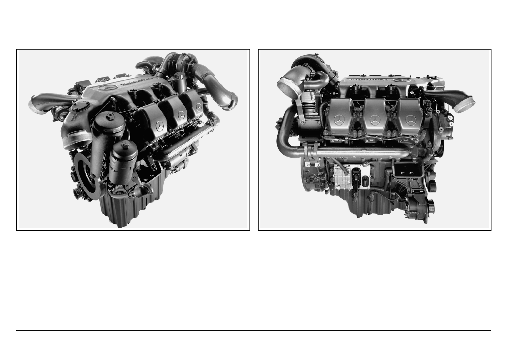
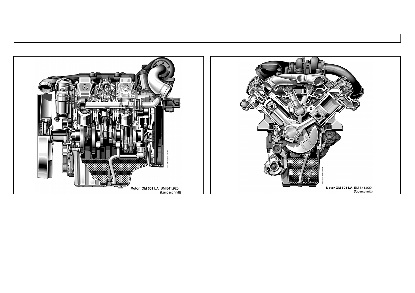
Engine OM 501 LA in cross section
N01.00-2009-50 N01.00-2010-50
05/03 Powersystems • Industrial Engines Maintenance and Repair Series 457, 500 and 900 Advanced Training
Series 500<>Technical features
69
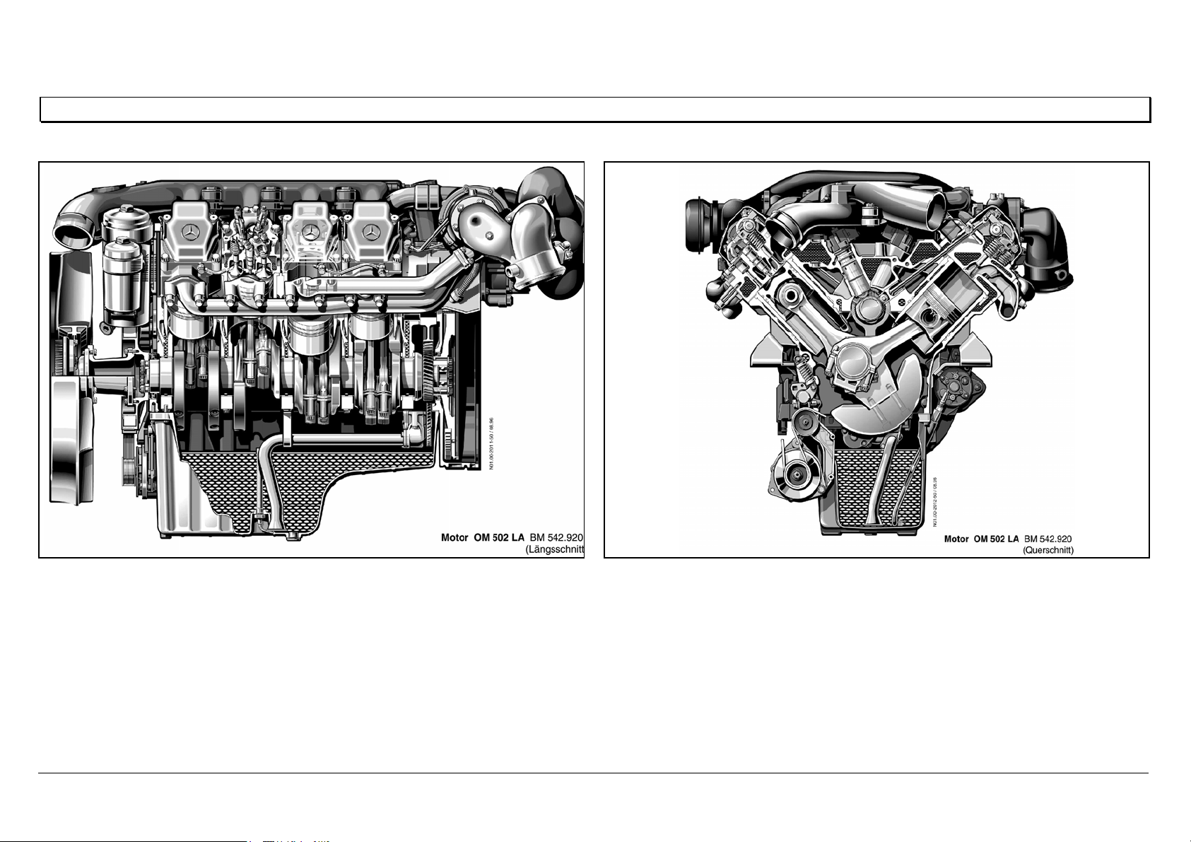
Engine OM 502 LA in cross section
N01.00-2011-50 N01.00-2012-50
05/03 Powersystems • Industrial Engines Maintenance and Repair Series 457, 500 and 900 Advanced Training
Series 500<>Cylinder head - port assignment
70
Series 500<>Cylinder head - port assignment 07.05.2003
Port assignment
A Coolant
BBolts
CPressure oil
D Oil return
E Plunger, oil return
N01.30-2024-12
E
A
E
B
B
D
B
A
B
A
B
C
05/03 Powersystems • Industrial Engines Maintenance and Repair Series 457, 500 and 900 Advanced Training
Series 500<>Cylinder head
71
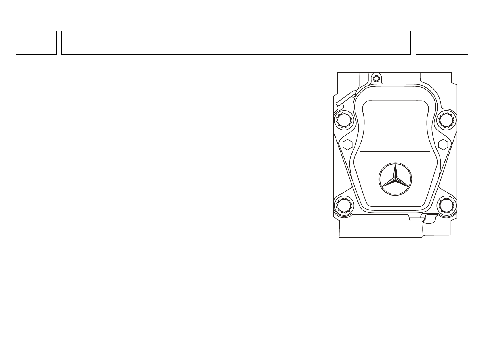
Series 500<>Cylinder head 07.05.2003
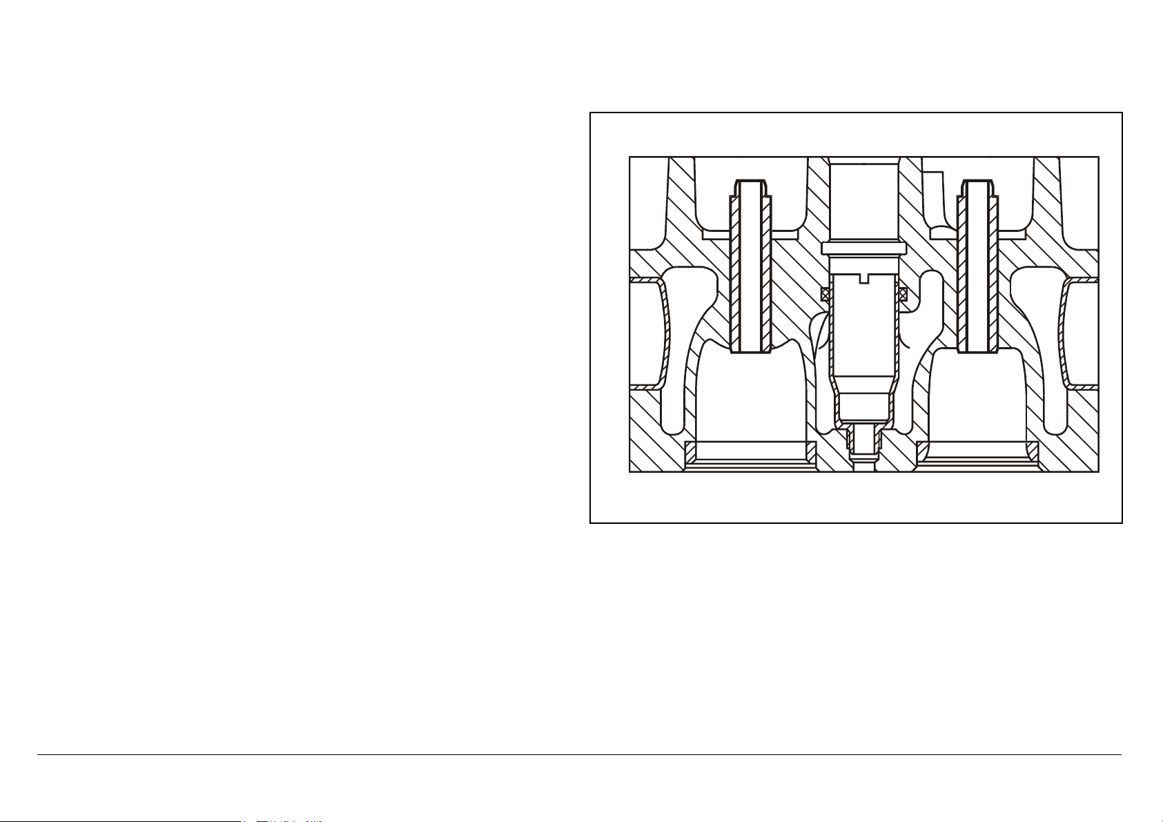
The individual cylinder heads are made of high-quality molybdenum/cast iron alloy. Each has four stretch-
thread bolts (M18x2), with which it is bolted to the crankcase.
The optimal position for the injection nozzle is the vertical position at the center of the combustion
chamber.
This ideal arrangement can only be achieved by using multi-valve technology.
This consists in arranging the valves in pairs (2 intake, 2 exhaust) around the injection nozzle.
A fifth valve is required for the constant throttle or the decompression valve/engine brake.
In both cases, these are linked to the exhaust port through an exactly adjusted hole.
N01.30-2025-02
05/03 Powersystems • Industrial Engines Maintenance and Repair Series 457, 500 and 900 Advanced Training
Series 500<>Cylinder head
72
The high-temperature, wear-resistant valve seat rings are inserted deep-frozen
into the floor panel.
The nozzle holder is inserted in a protective sleeve, which is washed around
by coolant and thus individually cooled.
The nozzle protective sleeve is sealed by an O-ring against coolant escape,
and by the thread and face against gas escape.
N07.03-2035-11
05/03 Powersystems • Industrial Engines Maintenance and Repair Series 457, 500 and 900 Advanced Training
Series 500<>Cylinder head mounting
73
Series 500<>Cylinder head mounting 07.05.2003
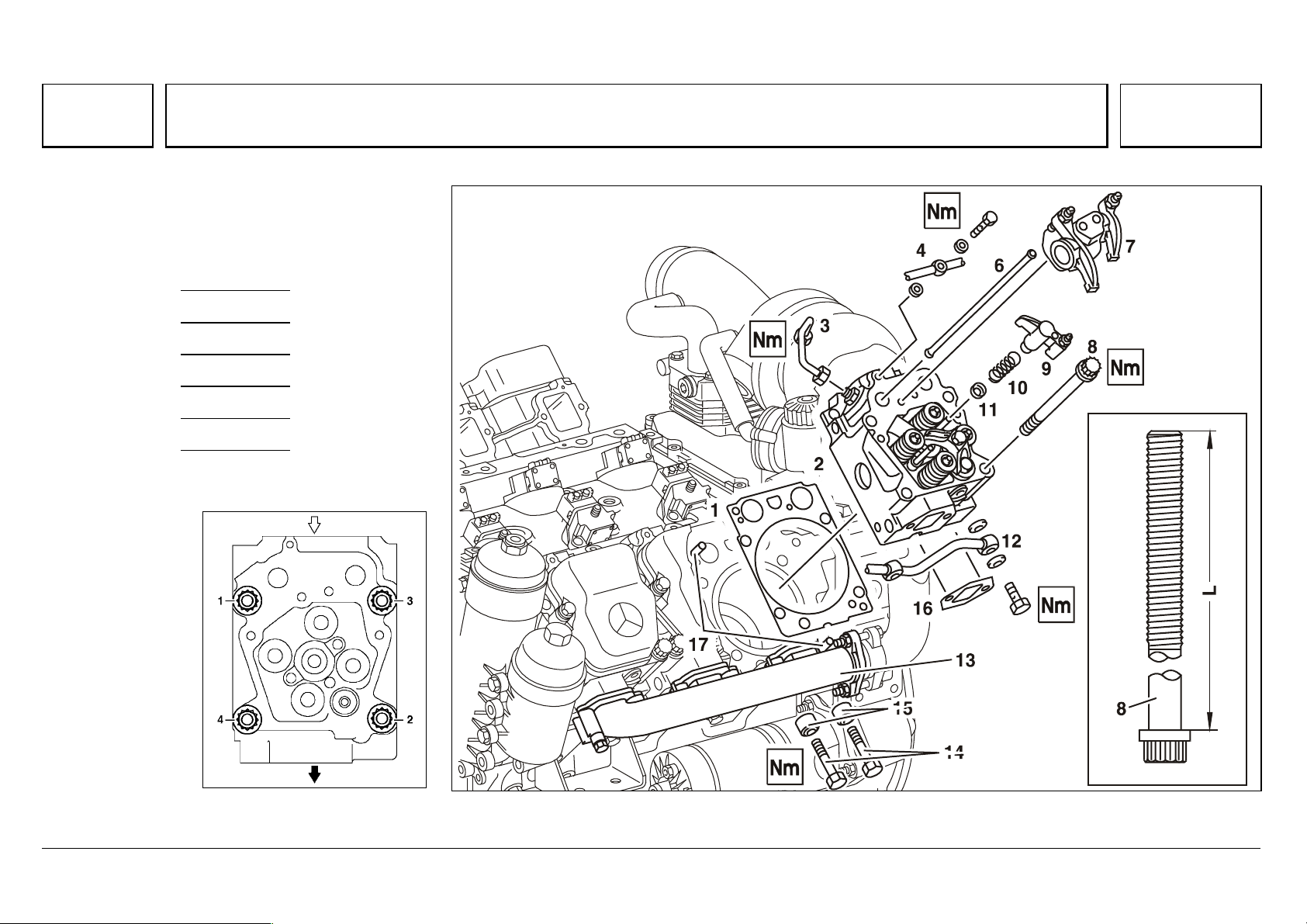
The cylinder head is tightened in 6 stages.
The cylinder head bolts do not require
retightening.
Step 1 10 Nm
Step 2 50 Nm
Step 3 100 Nm
Step 4 200 Nm
Step 5 90 °
Step 6 90 °
1 L T 212 mm
W01.30-0009-02 W01.30-0010-06
05/03 Powersystems • Industrial Engines Maintenance and Repair Series 457, 500 and 900 Advanced Training
Series 500<>Cylinder head gasket
74
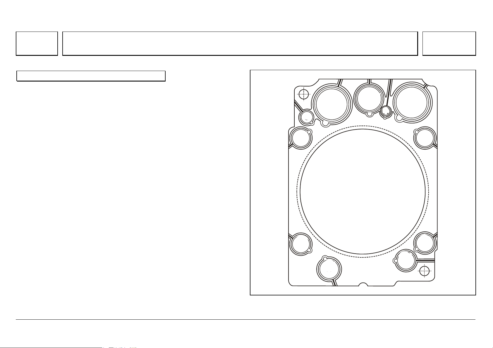
Series 500<>Cylinder head gasket 07.05.2003
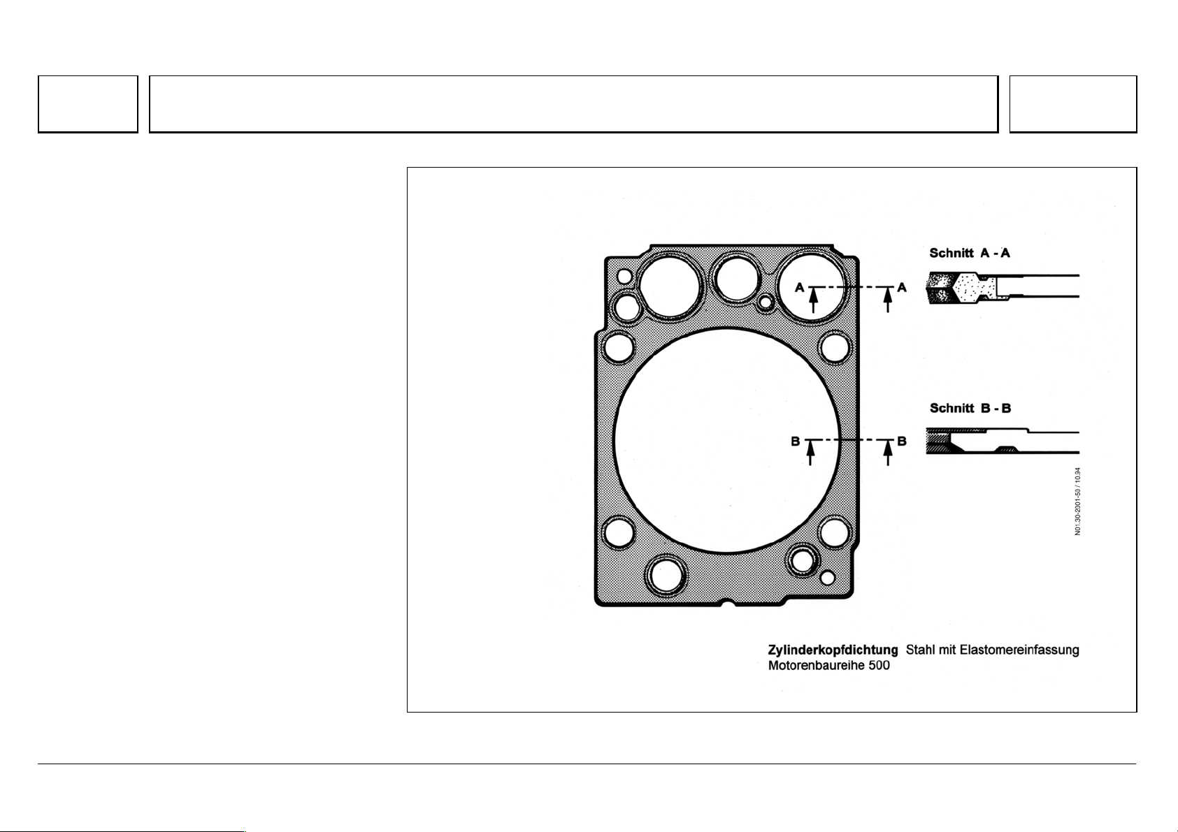
Each cylinder head has a stainless steel insert
gasket with scorched elastomer binding, which
does not require retightening.
N01.30-2001-50
05/03 Powersystems • Industrial Engines Maintenance and Repair Series 457, 500 and 900 Advanced Training
Series 500<>EURO 2 and EURO 3 cylinder heads compared
75
Series 500<>EURO 2 and EURO 3 cylinder heads compared 07.05.2003
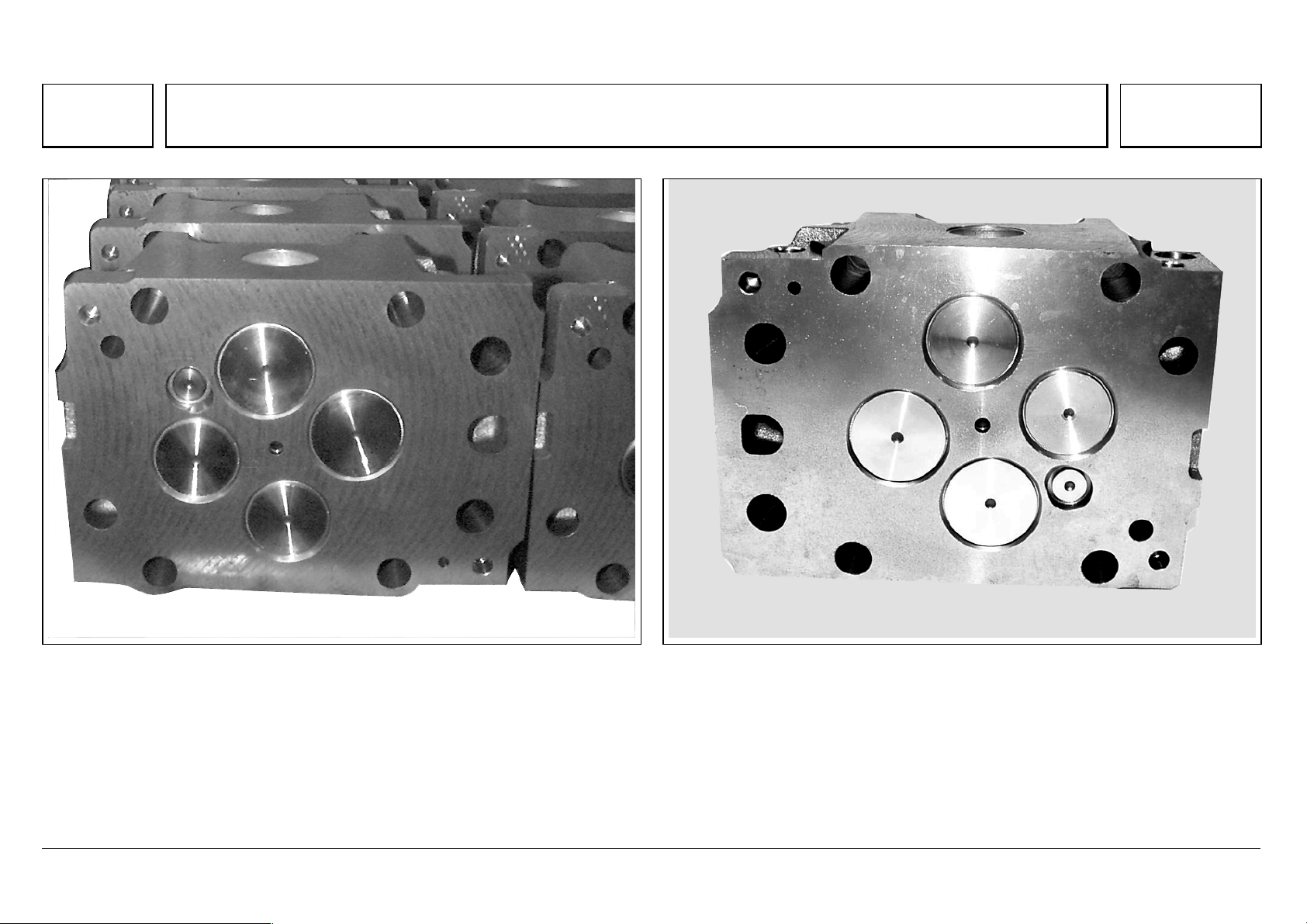
Cylinder head old version, as of 04/99
N01.30-2065-11
Cylinder head, Euro 3 version
N01.30-2064-11
In the previous Euro 2 version, the cover surfaces were milled.
Since 2000, as part of the "Euro 3" package of measures, the cylinder head
surfaces are turned, to a specific surface quality.
Since 06/2000, this also applies to all Euro 2 V8 and 315 kW V6 engines,
and from January 2001 to all other V6 engines.
The new cylinder heads should be ground to a minimum height of 113.5 mm,
by face grinding only. The surface quality (peak-to-valley height and
corrugation depth) is to be observed in all cases.

05/03 Powersystems • Industrial Engines Maintenance and Repair Series 457, 500 and 900 Advanced Training
Series 500<>EURO 2 and EURO 3 cylinder heads compared
76
05/03 Powersystems • Industrial Engines Maintenance and Repair Series 457, 500 and 900 Advanced Training
Series 500<>Valve assembly
77
Series 500<>Valve assembly 07.05.2003
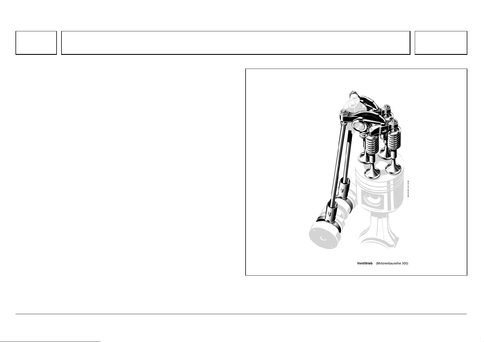
Gas exchange is improved by 4-valve technology, thus contributing
considerably to lower fuel consumption with lower emissions.
The intake and exhaust valves are controlled by means of roller tappets, push
rods and intake and exhaust rocker arms which are set in a groove in the
crankcase with a sliding block, and which operate the intake/exhaust valve
pairs through a valve bridge.
The rocker arm spindle complete with preassembled rocker arms and rocker
arm bearing bracket is bolted to the cylinder head.
To keep wear in the whole valve assembly to a minimum throughout its
lifetime, the contact surfaces of the valve, valve bridge, the rocker arm thumb,
the upset ball socket of the push rod, and the ball head of the adjusting
screw, are induction hardened. This is to allow them to support the actuation
forces of the high-temperature valve springs, and the effects of inertial forces
and cylinder pressures.
N05.30-2001-50
05/03 Powersystems • Industrial Engines Maintenance and Repair Series 457, 500 and 900 Advanced Training
Series 500<>Valve assembly
78
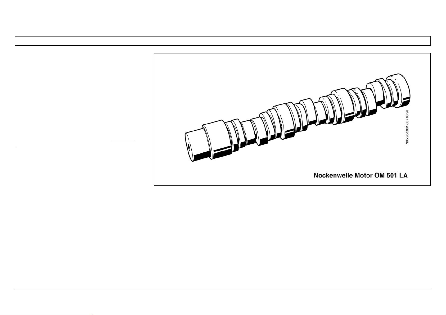
Camshaft
The camshaft is made of high-strength material,
with induction-hardened running surfaces, and
has 4 bearings in the OM 501 LA, 5 bearings in
the OM 502 LA.
Between the bearings are 4 valve timing cams
and 2 injection cams for each opposing cylinder
pair.
The slide ways of the timing cams for the valve
and injection roller tappets are supplied with lube
oil through additional oil holes in the piston jet
pipe.
N05.20-2001-50
05/03 Powersystems • Industrial Engines Maintenance and Repair Series 457, 500 and 900 Advanced Training
Series 500<>Valve assembly
79
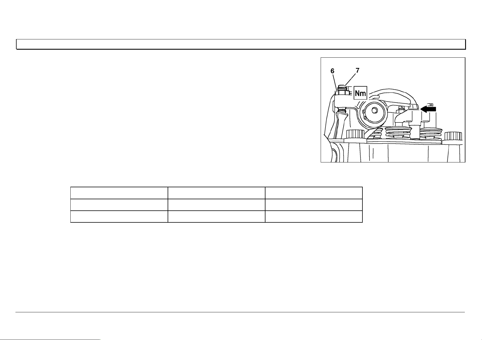
Adjusting the valve play
The valve play checking and setting procedure is the same as for the BR 400, and there are two methods.
Method 1
Set the intake and exhaust valves for each cylinder, according to the injection sequence.
The cylinder to be set must be at ignition TDC, the parallel cylinder at valve overlap TDC.
With this method, the crankshaft must be turned six times in the 6-cylinder engine, and eight times in the
8-cylinder engine.
Method 2
Set the intake and exhaust valves in two crankshaft positions.
Adjust when cylinder 1 is at ignition TDC.
Adjust when cylinder 1 is at overlap TDC.
N05.30-0302-01 P
Valve Play
Tolerance
Intake 0.40 + 0.20 / - 0.10
Exhaust 0.60 + 0.20 / - 0.10
The valve play test tolerance applies only for checking valve play.
If valve play is outside the tolerance range, the specified value must be set.
05/03 Powersystems • Industrial Engines Maintenance and Repair Series 457, 500 and 900 Advanced Training
Series 500<>Valve assembly
80
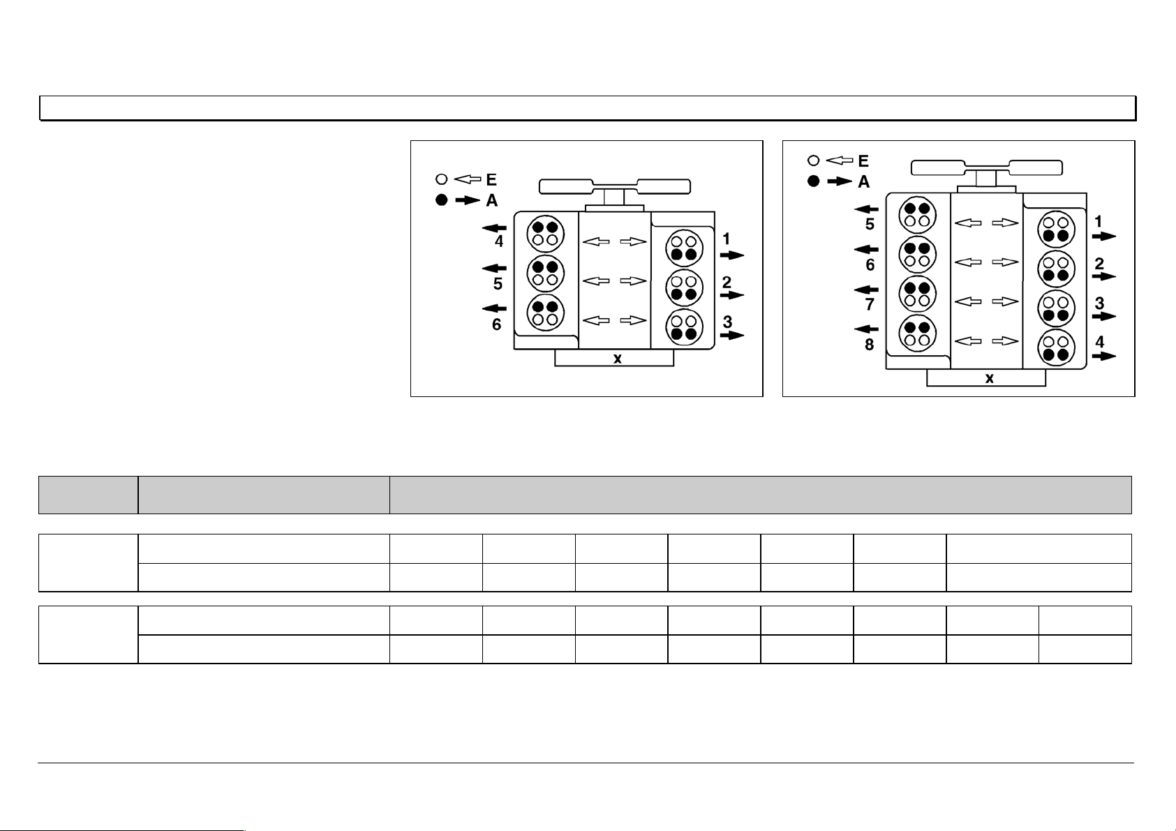
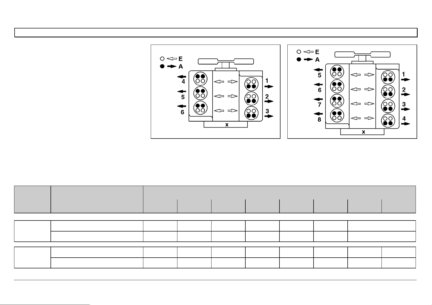
General notes on valve adjustment
Method 1
Set the intake and exhaust valves for each
cylinder, according to the injection sequence.
The cylinder to be set must be at ignition TDC, and
the parallel cylinder at valve overlap TDC.
AExhaust valve
E Intake valve
X Flywheel side
N01.00-0200-01 N01.00-0201-01
Engine Crankshaft position Cylinder/injection sequence
6-cylinder Ignition TDC142536
Valve overlap536142
8-cylinder
Ignition TDC15726348
Valve overlap63481572
05/03 Powersystems • Industrial Engines Maintenance and Repair Series 457, 500 and 900 Advanced Training
Series 500<>Valve assembly
81
General notes on valve adjustment
Method 2
Set the intake and exhaust valves at two
crankshaft positions, as shown in the table.
AExhaust valve
E Intake valve
X Flywheel side
N01.00-0200-01 N01.00-0201-01
6-cylinder
First set cylinder 5 at valve overlap TDC (cylinder
1 at ignition TDC), then cylinder 1 at valve
overlap TDC (cylinder 5 at ignition TDC).
8-cylinder
First set cylinder 6 at valve overlap TDC (cylinder
1 at ignition TDC), then cylinder 1 at valve
overlap TDC (cylinder 6 at ignition TDC).
Engine Crankshaft position Cylinder/injection sequence
1 2 3 4 5 6 7 8
6-cylinder
Cylinder 5 valve overlap I / E E I E - I
Cylinder 1 valve overlap - I E I I / E E
8-cylinder
Cylinder 6 valve overlap I / E E I I E - E I
Cylinder 1 valve overlap - I E E I I /E I E

05/03 Powersystems • Industrial Engines Maintenance and Repair Series 457, 500 and 900 Advanced Training
Series 500<>Valve assembly
82
05/03 Powersystems • Industrial Engines Maintenance and Repair Series 457, 500 and 900 Advanced Training
Series 500<>Pump-line-nozzle injection system (PLD)
83
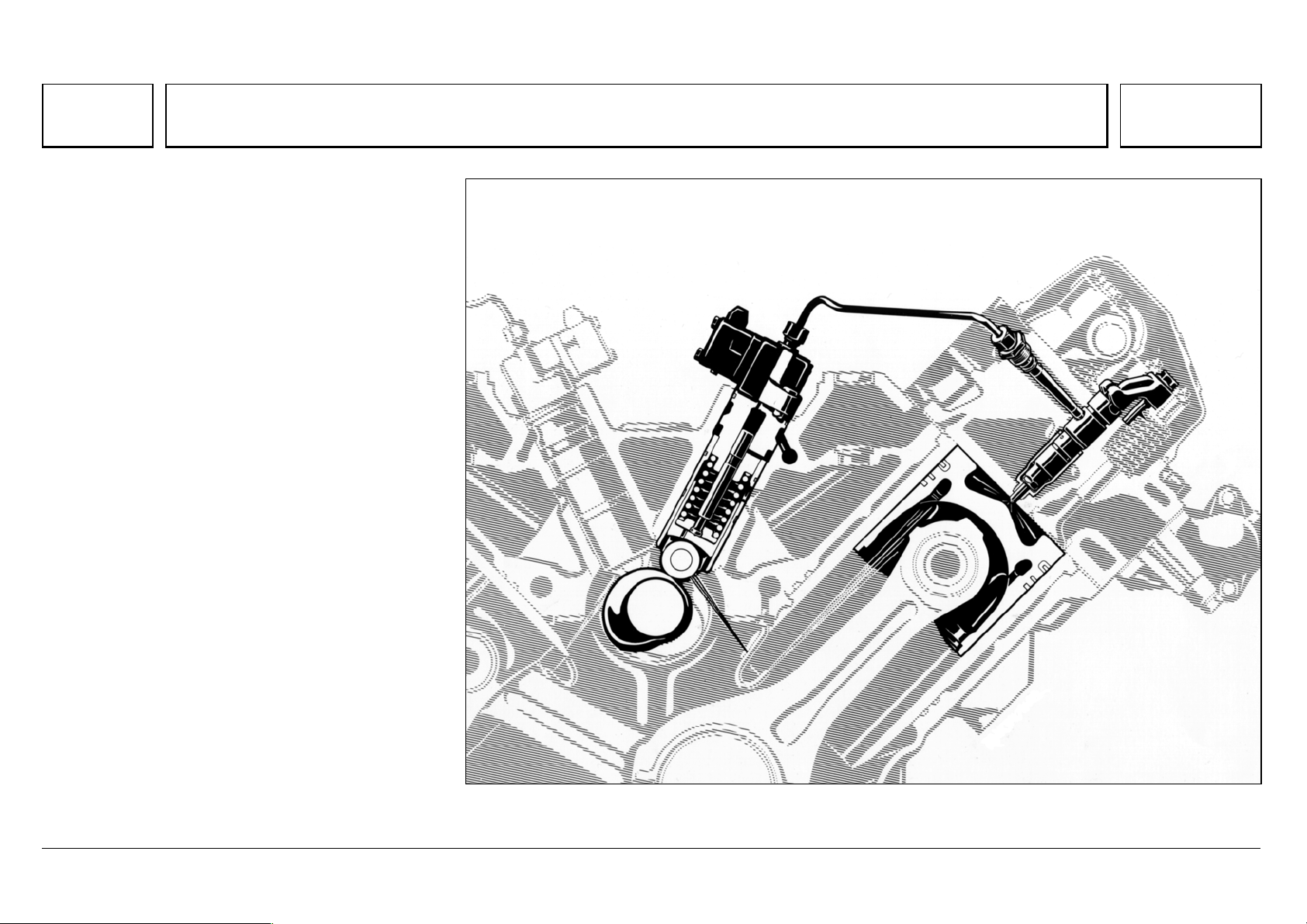
Series 500<>Pump-line-nozzle injection system (PLD) 07.05.2003
Engines of the OM 500 model series use the direct
fuel injection process.
The injection process is performed by the newly
developed pump-line-nozzle (PLD) system,
controlled by an electronic engine management
system that has also been newly developed.
In the PLD system, fuel is delivered to the injection
nozzle by individual unit pumps over short, rigid
high-pressure injection lines, and through the
pressure pipe connection screwed into the cylinder
head.
The connection to the nozzle and nozzle holder is
located centrally at the cylinder, and is integrated
with, and removable from, the cylinder head.
A unit pump fitted for each cylinder is located
directly on the crankcase.
N07.02-2018-50

05/03 Powersystems • Industrial Engines Maintenance and Repair Series 457, 500 and 900 Advanced Training
Series 500<>Pump-line-nozzle injection system (PLD)
84
The electronic engine management system controls the injection timing point and quantity injected individually per cylinder, by means of solenoid valves.
Separation of the high pressure pump and injection nozzle made it necessary to develop a high pressure injection line of special tube material with a surface
hardened by internal high pressure forming, able to support continuous injection pressures over 2000 bar.
With high pressure injection (peak pressures up to 1800 bar) together with the central, vertically positioned nozzle with 8 or 6 injection orifices and flat
combustion chamber cavity in the piston, outstanding particulate values are achieved.
Advantages over the Pump-Nozzle system
¦ No overhead camshaft
- therefore lower space requirement and reduced engine height
- lower noise emission
¦ On the V-engine, only one camshaft needed, which controls both cylinder banks.
- Weight saving
¦ Locating the camshaft in the center of the crankcase means there is optimal power absorption. With an overhead camshaft, measures would be
necessary for strengthening the cylinder head.
¦ Easy to repair
- Individual cylinder heads, which are all identical
- Compact unit pumps, which are simple to replace
- Inexpensive replacement due to separate pump and nozzle
 Loading...