


Towing - Recovery
Atego
Service
Towing – Recovery
Atego
Guidelines for Breakdown Services
2009 Edition
Daimler AG · Teile-Technik und Technische Information (GSP/TID) · D-70546 Stuttgart


 Information and copyright
If you have any questions or problems in connection with the towing or recovery of Atego vehicles, please contact:
Daimler AG
Technical Field Service
Tel. +49 711/17 – 59 762
Technical details of the data and illustrations provided in these guidelines are subject to change without notice.
Reprinting, reproduction or translation, in whole or in part, is not permissible without the written consent of Daimler AG.
All rights reserved by Daimler AG.
If you have any questions or suggestions concerning this product, please write to us at:
E-mail: customer.support@daimler.com
Fax: |
+49-(0) 18 05/0 12-79 78 |
or
Address: Daimler AG
GSP/TIS
HPC R822, W002
D-70546 Stuttgart
Technical status: 02/2008
© 2008 Copyright Daimler AG
This Manual, including all its parts, is protected under the laws of copyright. Any further processing or use requires the previous written consent of Daimler AG. This applies in particular to reproduction, distribution, alteration, translation, microfilming and storage and/or processing in electronic systems, including databases and online services.

|
|
Contents |
|
|
|
|
|
|
|
|
|
|
|
|
|
|
General |
|
|
|
|
|
|
|
Safety and liability information |
6 |
|
|
Conventions |
6 |
|
|
Vehicle identification |
7 |
|
|
|
|
|
|
Description and roadside assistance |
|
|
|
|
|
|
|
Quick guide |
9 |
|
|
Instrument panel |
11 |
|
|
Overview |
11 |
|
|
Standard onboard computer |
16 |
|
|
Plus onboard computer |
20 |
|
|
Display messages |
27 |
|
|
STOP lamp |
29 |
|
|
Symbol and text messages |
30 |
|
|
System abbreviations |
42 |
|
|
Indicator lamps |
43 |
|
|
Warning buzzer |
46 |
|
|
Oil level in engine |
48 |
|
|
Oil level in automatic transmission |
50 |
|
|
Fuel system |
53 |
|
|
Overview of fuel system |
53 |
|
|
Hand pump (location) |
56 |
|
|
Checking the fuel system |
57 |
|
|
Electrical system |
59 |
|
|
EMERGENCY OFF switch |
60 |
|
|
Jump starting |
61 |
|
|
Batteries |
62 |
|
|
Fuses |
64 |
|
Guidelines for Breakdown Services (Subject to technical modifications) i |
|
3 |
|
|
|


 Contents
Transmission |
68 |
Manual gearshift system |
69 |
Automatic transmission |
71 |
Telligent® automatic gearshift system |
73 |
Teach-in process (vehicles with Telligent® automatic |
|
gearshift system) |
75 |
Teach-in errors |
77 |
Emergency shift (live PTO) |
78 |
Brake system |
78 |
General |
78 |
Frequent-stop brake |
79 |
Hill holder |
80 |
Overview of compressed air reservoirs |
81 |
Filling the compressed air system from an external source |
81 |
Releasing the spring-loaded parking brake |
82 |
Telligent® level control |
86 |
Diagram of Telligent® level control |
86 |
Raising/lowering the chassis frame |
88 |
Filling the air suspension system from an external source |
90 |
Tilting the cab |
91 |
Engine |
95 |
Starting/stopping the engine with the cab tilted |
95 |
|
|
Tow-starting |
|
|
|
Tow-starting |
97 |
General |
97 |
Preparations for tow-starting |
97 |
Tow-starting vehicles with manual gearshift system |
98 |
Vehicles with Telligent® automatic gearshift system |
99 |
|
|
Towing |
|
|
|
Quick guide |
100 |
Towing |
101 |
General |
101 |
Electrical circuits |
103 |
Air brake system |
104 |
Stopped engine, transmission and/or axle damage |
107 |
Drive shafts |
108 |
Preparations for towing |
111 |
4 |
|
i |
Guidelines for Breakdown Services (Subject to technical modifications) |
|
|
|
|

|
|
Contents |
|
|
|
|
|
|
|
|
|
|
|
|
|
|
Recovery |
|
|
|
|
|
|
|
Recovery |
118 |
|
|
General |
118 |
|
|
Maximum permissible pulling forces |
119 |
|
|
Safety components |
120 |
|
Special tools
Special tools |
121 |
Guidelines for Breakdown Services (Subject to technical modifications) i |
|
5 |
|
|
|

General

 Safety and liability information
The aim of these guidelines is to provide roadside assistance and towing personnel with the instructions and information necessary in order to remove the vehicle from the scene of the breakdown or accident within 30 minutes whenever possible.
These guidelines assume that the reader understands and complies with the pertinent accident prevention regulations, any relevant professional guidelines for vehicle ownership or recovery and towing company association regulations, and the road traffic regulations of the country in question.
The instructions in these guidelines, in particular those pertaining to vehicle recovery, are intended exclusively for experienced recovery specialists and are left to the discretion of the user.
Compensation and/or warranty claims arising from towing or recovery measures will not be accepted by Daimler AG.
Risk of accident |
G |
All vehicles that have been towed or recovered from a breakdown must be examined for technical condition and checked for damage at a qualified workshop which possesses all the expertise and tools required to properly perform the necessary work.
Mercedes-Benz recommends a Mercedes-Benz service center for this work. It is absolutely essential that all safety-relevant work and all work on safety-relevant systems is performed by a qualified specialist workshop.
Pay attention to the notes in the chapter "Recovery", see page 8.
Risk of accident |
G |
Tampering with electronic components and their software can cause them to stop functioning. The electronic systems are networked together by interfaces. In some cases, interfering with these electronic systems can also cause malfunctions in systems that were not directly affected. Such malfunctions can put the operational safety of your vehicle, and thus your own personal safety, at considerable risk.
Other improperly performed work or modifications to the vehicle can also jeopardize operational safety.
Some safety systems operate only when the engine is running. For this reason, do not switch the engine off while driving.
Conventions
GWarning
HEnvironmental warning
!Potential damage
iTip
Instruction
Displays On-screen display
6 iGuidelines for Breakdown Services (Subject to technical modifications)
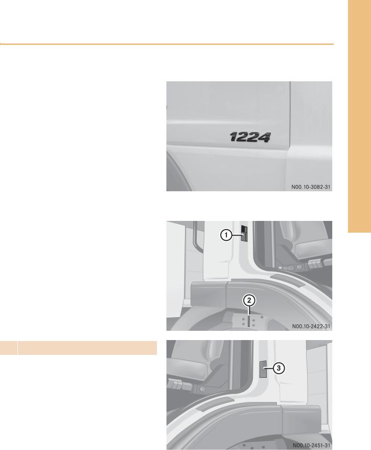
Vehicle identification 
Vehicle model designation
12 |
24 |
|
|
|
|
12 |
|
Permissible gross vehicle weight in |
|
|
tonnes |
|
24 |
Engine output in hp (x 10) |
|
|
|
Location of vehicle model plate/vehicle identification number
1 |
Model plate (example) |
2 |
Vehicle identification number on right |
|
longitudinal frame member |
|
|
General
3Vehicle identification number (example)
Guidelines for Breakdown Services (Subject to technical modifications) i |
|
7 |
|
|
|

General

 Vehicle identification
Data on the vehicle model plate
•Vehicle model
•Headlamp basic setting
•Smoke index
•Rear axle ratio
•Vehicle identification number (VIN)
•Permissible gross vehicle weight
•Permissible axle loads
|
|
|
|
|
|
(example) |
Key to vehicle identification number |
||||||
|
|
|
|
|
||
Vehicle identification number (VIN) |
|
|||||
|
|
|
|
|
|
|
WDB |
970.213 1 K 896063 |
|
||||
WDB |
|
|
|
|
|
Vehicle manufacturer |
|
970.213 |
|
|
|
Vehicle model designation (see below) |
|
|
|
|
1 |
|
|
Steering (1 = left-hand drive vehicles, 2 = right-hand drive vehicles) |
|
|
|
|
K |
|
Code letter or code number of manufacturing plant |
|
|
|
|
|
896063 |
Vehicle identification end number |
|
|
|
|
|
|
|
|
|
|
|
|
|
|
970 |
.2 |
1 |
|
|
|
|
|
|
|
||||
970 |
|
Model designation/vehicle version |
||||
970 = Platform vehicle
972 = Dumper vehicle
974 = Semitrailer tractor
975 = Municipal vehicle
976 = Fire-fighting vehicle
.2 Suspension/drive configuration (abbreviation)
0 = Steel suspension
2 = Air suspension
3 = Steel suspension/all-wheel drive
1Tonnage (abbreviation)
4 x 2 |
|
4 |
Number of wheels or wheel pairs |
|
x2 Number of driven wheels or wheel pairs |
8 iGuidelines for Breakdown Services (Subject to technical modifications)
Quick guide 
Instrument panel |
|
Overview.......................................................................................................... |
Page 11 |
Reservoir pressure gauge for brake circuit 1 or 2............................................ |
Page 12 |
Gear indicator .................................................................................................. |
Page 13 |
Fuel/AdBlue® level gauge ............................................................................... |
Page 14 |
Standard onboard computer............................................................................ |
Page 16 |
Plus onboard computer.................................................................................... |
Page 20 |
Display messages ............................................................................................ |
Page 27 |
STOP lamp ....................................................................................................... |
Page 29 |
Symbol and text messages .............................................................................. |
Page 30 |
Display messages with yellow status indicator ................................................ |
Page 30 |
Display messages with red status indicator..................................................... |
Page 36 |
System abbreviations ...................................................................................... |
Page 42 |
Indicator lamps ................................................................................................ |
Page 43 |
Warning buzzer |
|
Warning buzzer ................................................................................................ |
Page 46 |
Oil level in engine |
|
Calling up the engine oil level on the display ................................................... |
Page 48 |
Topping up the engine oil................................................................................. |
Page 49 |
Oil level in automatic transmission |
|
Checking the transmission oil level ................................................................. |
Page 50 |
Fuel system/AdBlue® |
|
Overview of fuel system................................................................................... |
Page 53 |
Fuel tank.......................................................................................................... |
Page 54 |
Hand pump ...................................................................................................... |
Page 56 |
Checking the fuel system ................................................................................ |
Page 57 |
Bleeding/dewatering the fuel system.............................................................. |
Page 57 |
Electrical system |
|
Overview of electrical system .......................................................................... |
Page 59 |
EMERGENCY OFF switch ................................................................................. |
Page 60 |
Jump starting ................................................................................................... |
Page 61 |
Batteries .......................................................................................................... |
Page 62 |
Fuses ............................................................................................................... |
Page 64 |
Description and roadside assistance
Guidelines for Breakdown Services (Subject to technical modifications) i |
|
9 |
|
|
|

Description and roadside assistance

 Quick guide
Transmission |
|
Overview of transmissions ............................................................................... |
Page 68 |
Manual gearshift system.................................................................................. |
Page 69 |
Automatic transmission ................................................................................... |
Page 71 |
Telligent® automatic gearshift system............................................................. |
Page 73 |
Teach-in process for Telligent® automatic gearshift system............................ |
Page 75 |
Teach-in errors................................................................................................. |
Page 77 |
Emergency shift of power take-off (live PTO) ................................................... |
Page 78 |
Brake system |
|
General ............................................................................................................ |
Page 78 |
Frequent-stop brake ........................................................................................ |
Page 79 |
Hill holder ........................................................................................................ |
Page 80 |
Overview of compressed air reservoirs ............................................................ |
Page 81 |
Filling the compressed air system from an external source ............................. |
Page 81 |
Spring-loaded parking brake............................................................................ |
Page 82 |
Releasing pneumatically ............................................................................. |
Page 82 |
Releasing mechanically .............................................................................. |
Page 83 |
Telligent® level control |
|
Diagram of Telligent® level control .................................................................. |
Page 86 |
General ............................................................................................................ |
Page 87 |
Level control operating unit ............................................................................. |
Page 87 |
Raising/lowering the chassis frame ................................................................ |
Page 88 |
Filling the air suspension system from an external source .............................. |
Page 90 |
Tilting the cab |
|
Before tilting .................................................................................................... |
Page 91 |
Mechanical ...................................................................................................... |
Page 91 |
Mechanical/hydraulic...................................................................................... |
Page 93 |
Engine |
|
Starting and stopping the engine with the cab tilted ....................................... |
Page 95 |
10 iGuidelines for Breakdown Services (Subject to technical modifications)
Instrument panel 
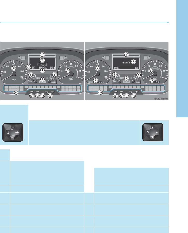
Overview
Standard |
Plus onboard |
onboard |
computer |
computer |
|
|
|
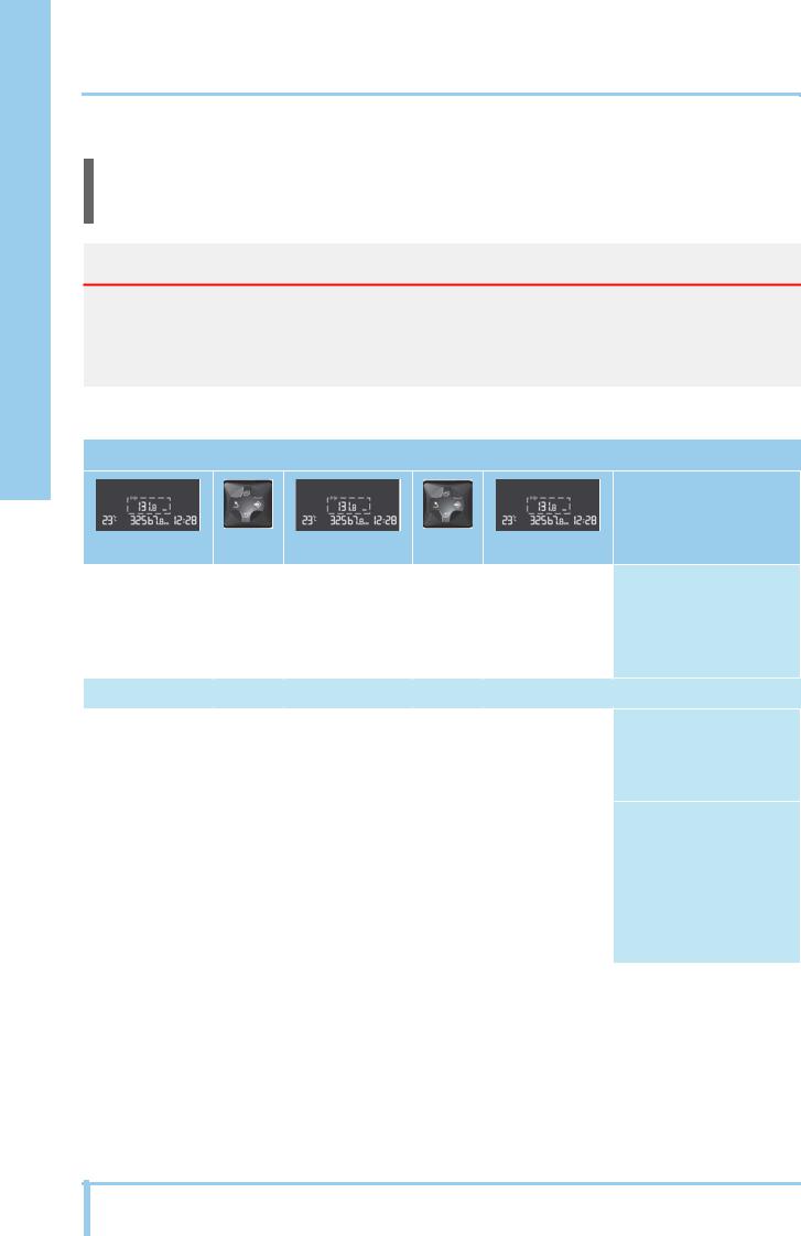
The Standard and Plus onboard computers can be distinguished by the symbols on the control pad. Vehicles with Plus onboard computer have an additional display in the tachometer (outside/coolant temperature display 3) and a display in the speedometer (total mileage 4).
1 |
Status indicator |
8 |
Fuel/AdBlue® level gauge |
|
|
(see page 28) |
|
(see page 14) |
|
|
Display |
|
Speedometer |
|
2 |
9 |
|||
|
|
|
|
|
|
Vehicles with |
a |
Instrument illumination |
|
|
• Standard onboard computer (see page 16) |
|
• |
+ brighter |
|
• Plus onboard computer (see page 20) |
|
• |
- darker |
3 |
Outside/coolant temperature display |
b |
Reset button |
|
|
|
|
|
|
4 |
Total mileage |
c |
Selector button for outside/coolant |
|
|
|
|
temperature display |
|
5 |
Tachometer |
d |
TRIP button for resetting trip mileage and for |
|
|
|
|
trip data or trip computer |
|
6 |
Reservoir pressure gauge for brake circuit |
e |
Indicator lamps |
|
|
1 or 2 (see page 12) |
|
(see page 43) |
|
7STOP lamp (see page 29)
Description and roadside assistance
Guidelines for Breakdown Services (Subject to technical modifications) i |
|
11 |
|
|
|

Description and roadside assistance

 Instrument panel
Reservoir pressure gauge for brake circuit 1 or 2
1 |
Brake circuit 1 indicator lamp |
2 |
Brake circuit 2 indicator lamp |
3 |
Reservoir pressure gauge for brake circuit |
|
1 or 2 |
|
|
Turn vehicle key in steering lock to drive position.
The brake circuit with the lowest reservoir pressure is displayed automatically by the appropriate indicator lamp 1 or 2. The gauge 3 shows the pressure in this brake circuit.
i
Vehicles with Plus onboard computer:
The reservoir pressure of both brake circuits can be shown in the display.
To do this, call up menu Check Info > Reservoir Pressure (see page 25).
Risk of accident |
G |
Leaks in the compressed air brake system put the operational safety of the vehicle at risk. If the reservoir pressure in the compressed air brake system is too low, it is not possible to brake the vehicle. This could make you cause an accident with possible injury to yourself and others.
Do not set the vehicle in motion until the reservoir pressures have been reached and the STOP lamp has gone out.
If the display shows —, do not start to move the vehicle or, if moving, stop it as quickly as possible taking into account the traffic situation. In addition, the segments of the status indicator light up red and the STOP lamp does not go out.
Have the brake system checked and repaired as quickly as possible at a qualified specialist workshop possessing the required expertise and tools in order to perform the necessary work.
Mercedes-Benz recommends a Mercedes-Benz service center for this work. It is absolutely essential that all safety-relevant work and all work on safety-relevant systems is performed by a qualified specialist workshop.
The necessary reservoir pressure for the service brake is 10 bar (constant pressure system).
The ancillary consumer circuit is filled only after brake circuits 1 and 2 have been filled.
The operational safety of the vehicle requires an adequate reservoir pressure in brake circuits 1 and 2 (10 bar) and in the ancillary consumer circuit (8.5 bar).
12 iGuidelines for Breakdown Services (Subject to technical modifications)

Gear indicator
Telligent® automatic gearshift system
Ì |
Standard onboard computer |
Í |
Plus onboard computer |
1 |
Engaged: 4th gear |
2 |
Recommended or preselected: 3rd gear |
|
|
The display shows the engaged gear 1 and the recommended or preselected gear 2.
1-6 1st to 6th gear
NTransmission neutral
RReverse gear
Instrument panel 
Description and roadside assistance
Guidelines for Breakdown Services (Subject to technical modifications) i |
|
13 |
|
|
|
Description and roadside assistance

 Instrument panel
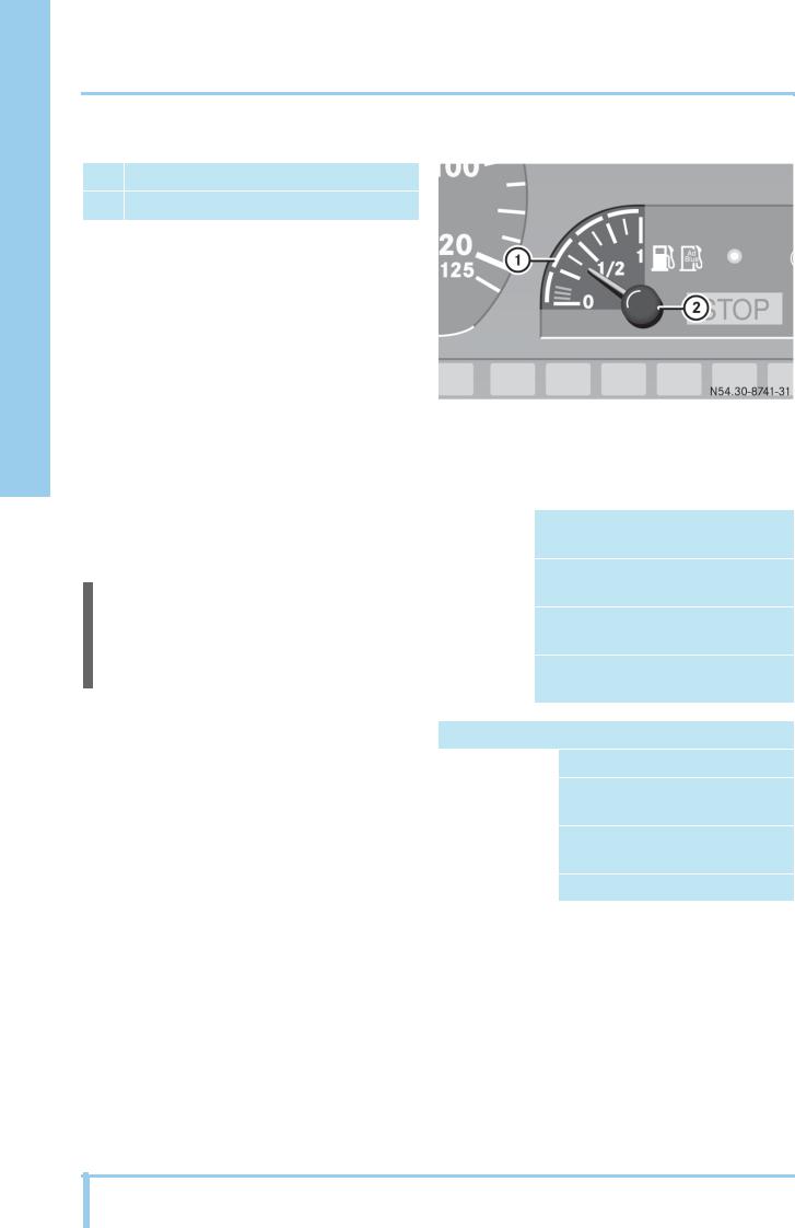
Fuel/AdBlue® level gauge
1AdBlue® level gauge
2Fuel level gauge
Turn vehicle key in steering lock to drive position.
Check level on fuel/AdBlue® level gauge and top up if necessary.
Switch off the engine and the auxiliary heater before filling the reservoir.
Fuel reserve indicator
When the content of the fuel tank has dropped to about 14%, the display shows W. At the same time the segments of the status indicator light up yellow.
AdBlue® level gauge
The AdBlue® level gauge 1 provides only a rough indication of the AdBlue® supply. The AdBlue® level is indicated by 4 blue segments in the Instrument.
i
The current AdBlue® level in liters can be called up on the display of the Standard onboard computer (see page 18) or the Plus onboard computer (see page 25).
If the AdBlue® reservoir is empty or there is a malfunction in the BlueTec® exhaust aftertreatment system, the indicator lamp ±lights up. A display message also appears. In this case the vehicle must be refueled with AdBlue® or the fault must be rectified immediately.
1 segment |
|
AdBlue® level between reserve and |
|
|
|
tank 1/4 full |
|
2 segments |
|
AdBlue® level between |
|
|
|
tank 1/4 and 1/2 full |
|
3 segments |
|
AdBlue® level between |
|
|
|
tank 1/2 and 3/4 full |
|
4 segments |
|
AdBlue® level between |
|
|
|
tank 3/4 full and tank full |
|
|
|
|
|
AdBlue® level at reserve |
|||
Segments |
|
All segments are off |
|
Display |
|
Standard onboard computer: |
|
|
|
|
#RES |
|
|
|
Plus onboard computer: " |
|
|
|
Refuel AdBlue |
Indicator lamp |
|
- |
|
|
|
|
|
14 iGuidelines for Breakdown Services (Subject to technical modifications)

Instrument panel 
!
If the AdBlue® supply is exhausted or there is a malfunction, the engine power may be significantly reduced the first time the vehicle comes to
astandstill.1
1 The engine power is not reduced in emergency vehicles.
AdBlue® supply exhausted
Segments |
All segments are off |
|
|
Display |
Standard onboard computer: |
|
#0 l |
|
Plus onboard computer: " |
|
Refuel AdBlue |
Indicator lamp |
± |
|
|
Description and roadside assistance
Guidelines for Breakdown Services (Subject to technical modifications) i |
|
15 |
|
|
|
Description and roadside assistance

 Instrument panel
Standard onboard computer
Design and operation
The Standard onboard computer is activated as soon as you turn the vehicle key in the steering lock to the drive position. The Standard onboard computer allows you to call up information about your vehicle and to make and change various settings.
Risk of accident |
G |
Operating the onboard computer while driving can distract your attention away from what is happening on the road. You could lose control of the vehicle and cause an accident.
For this reason, only operate the onboard computer when the vehicle is stationary with the parking brake applied.
Buttons and display
1Display
2Control pad
º Back
è Page up/down
q Info
p Settings
3Reset button
4TRIP button
The control pad 2 and the buttons 3 and 4 on the instrument panel are used to operate the Standard onboard computer e.g. to call up displays or to change settings.
Display check
Turn vehicle key in steering lock to drive position. During the display check
•the warning buzzer sounds for about 1 second
•the segments of the status indicator light up yellow
•all the indicator lamps in the instrument panel light up for about 2 seconds
•the ABS equipment is checked
When the display check is complete, the default display appears.
i
If ABS equipment is detected, the display shows the ABS equipment for about 3 seconds after the display check.
16 iGuidelines for Breakdown Services (Subject to technical modifications)

Instrument panel 
Default display
1 |
Outside/coolant temperature display |
2 |
Main odometer |
3 |
Trip odometer |
4 |
Time |
|
|
The TRIP button can be used to change between the trip mileage display and the trip data in the instrument panel.
i
If the Standard onboard computer detects malfunctions in the system, the messages appear in sequence on the display and the segments of the status indicator lights up yellow or red, see page 27.
Confirming display messages, see page 28.
Display fields
The display fields are actuated according to the installed equipment or the activated functions.
1Status indicator
2Fault symbol fields
3Operating display for differential locks and PTOs
4Gear indicator
5System abbreviations
Description and roadside assistance
Status indicator
The segments of the status indicator 1 light up yellow or red to distinguish display messages according to their priority rating. Display message with yellow/red status indicator, see page 27.
System abbreviation or fault symbol
When a display message is shown on the Standard onboard computer, the display field shows the system abbreviation 5 of the affected control unit or a fault symbol, e.g. if the coolant temperature is excessively high. System abbreviations, see page 42.
Guidelines for Breakdown Services (Subject to technical modifications) i |
|
17 |
|
|
|
Description and roadside assistance

 Instrument panel
Menus in detail
i
The number and sequence of the menus depend on the vehicle model and the vehicle equipment. The values given are examples.
Risk of accident |
G |
Operating the onboard computer while driving can distract your attention away from what is happening on the road. You could lose control of the vehicle and cause an accident.
For this reason, only operate the onboard computer when the vehicle is stationary with the parking brake applied.
Menu overview
Menu structure
Description
Default display |
If the control pad is not |
|
pressed within a period of |
|
15 minutes after a menu is |
|
called up, the default |
|
display reappears. |
|
|
è
AdBlue # |
q Fuel level " q |
The Standard onboard |
|
56% 28l |
19% 66l |
computer displays the |
|
AdBlue® and fuel levels in |
|||
|
|
||
|
|
liters and percent. |
|
Engine oil level: |
q Engine operating |
Check engine oil level with |
|
OEL ok or OIL ok |
hours: |
engine at operating |
|
or 2.5l |
MTBS 192 h or |
temperature about |
|
|
HRS 192 h |
1 minute after switching |
|
|
|
off the engine. |
|
|
|
Top up engine oil if |
|
|
|
necessary. |
|
|
|
|
18 iGuidelines for Breakdown Services (Subject to technical modifications)
|
|
|
|
|
|
|
|
|
|
|
Instrument panel |
|
|
|
|
|
|
|
|
|
|
|
|
|
|
|
|
|
|
|
|
|
|
|
|
|
|
|
|
|
|
|
|
|
|
|
|
|
|
|
|
Menu structure |
|
|
|
|
|
|
|
|
|
|
|
|
|
|
|
|
|
|
|
|
|
|
|
Description |
|
|
|
|
|
|
|
|
|
|
|
|
|
|
|
|
|
|
|
|
|
|
|
|
|
|
|
|
|
|
|
|
|
|
|
|
|
|
|
|
Total axle load: |
q Axle load: |
q ... other axle |
The front axle (VA/FA) or |
|
||||||||
GES 23.5t or |
|
|
VA 7.5t or |
|
loads: |
rear axle (HA/RA) |
|
|||||
|
|
|
|
|
|
indicated flashes in the |
|
|||||
SUM 23.5t |
|
|
FA 7.5t |
|
Axle load HA 1 or |
|
||||||
|
|
|
display. |
|
||||||||
|
|
|
|
|
|
|
|
RA 1 |
|
|||
|
|
|
|
|
|
|
|
|
|
|||
|
|
|
|
|
|
|
|
Axle load HA 2 or |
The axle load display is not |
|
||
|
|
|
|
|
|
|
|
a calibrated system and |
|
|||
|
|
|
|
|
|
|
|
RA 2 |
|
|||
|
|
|
|
|
|
|
|
cannot be used for official |
|
|||
|
|
|
|
|
|
|
|
|
|
|
|
|
|
|
|
|
|
|
|
|
|
|
|
purposes. |
|
è |
|
|
|
|
|
|
|
|
|
|
|
|
Condensation: |
q Condensation: |
Reset |
Condensation: |
The menu only appears in |
|
|||||||
Æ |
|
|
reset |
button |
ok |
conjunction with a |
|
|||||
|
|
|
relevant display message, |
|
||||||||
|
|
|
|
|
|
|
|
|
|
|
|
|
|
|
|
|
|
|
|
|
|
|
|
(see page 31). In some |
|
|
|
|
|
|
|
|
|
|
|
|
cases the condensation |
|
|
|
|
|
|
|
|
|
|
|
|
message can be reset by |
|
|
|
|
|
|
|
|
|
|
|
|
pressing the Reset button. |
|
è |
|
|
|
|
|
|
|
|
|
|
|
|
Diagnosis 1: |
q Display |
q ... other display |
After the last display |
|
||||||||
FR 0004 463902 |
|
|
message 1: |
|
messages |
message the fault memory |
|
|||||
|
|
|
|
|
|
|
|
|
can be erased with the |
|
||
|
|
|
|
FR 0406 E01 |
|
|
|
|
|
|||
|
|
|
|
|
|
|
|
Reset button. Display |
|
|||
|
|
|
|
|
|
|
|
|
|
|
|
|
|
|
|
|
|
|
|
|
|
|
|
messages, see page 27. |
|
è |
|
|
|
|
|
|
|
|
|
|
|
|
Diagnosis.. |
q Display message |
q ... other display |
Other control units are |
|
||||||||
... |
... |
|
|
messages |
displayed with the |
|
||||||
|
|
|
|
|
associated system |
|
||||||
|
|
|
|
|
|
|
|
|
|
|
|
|
|
|
|
|
|
|
|
|
|
|
|
abbreviations, |
|
|
|
|
|
|
|
|
|
|
|
|
see page 42. |
|
|
|
|
|
|
|
|
|
|
|
|
|
|
Description and roadside assistance
Guidelines for Breakdown Services (Subject to technical modifications) i |
|
19 |
|
|
|

Description and roadside assistance

 Instrument panel
Plus onboard computer
Design and operation
The Plus onboard computer is activated as soon as you turn the vehicle key in the steering lock to the drive position. The Plus onboard computer allows you to call up information about your vehicle and to make and change various settings.
Risk of accident |
G |
Operating the onboard computer while driving can distract your attention away from what is happening on the road. You could lose control of the vehicle and cause an accident.
For this reason, only operate the onboard computer when the vehicle is stationary with the parking brake applied.
Buttons and display
1Display
2Control pad
‚ Page up
ƒ Page down
„ Select main menu/submenu, confirm settings
º Exit main menu/submenu, confirm display messages
3Reset button
4TRIP button
The control pad 2 and the buttons 3 and 4 on the instrument panel are used to operate the Plus onboard computer e.g. to call up submenus, to change settings, to confirm messages etc.
Display check
Turn vehicle key in steering lock to drive position. During the display check
•the warning buzzer sounds for about 1 second
•the segments of the status indicator light up yellow
•all the indicator lamps in the instrument panel light up for about 2 seconds
•the ABS equipment is checked
When the display check is complete, the default display appears.
i
If ABS equipment is detected, the display shows the ABS equipment for about 3 seconds after the display check.
20 iGuidelines for Breakdown Services (Subject to technical modifications)
Instrument panel 
i
If the Plus onboard computer detects malfunctions in the system, the display messages appear in sequence and the segments of the status indicator lights up yellow or red, see page 27.
Confirming display messages, see page 27.
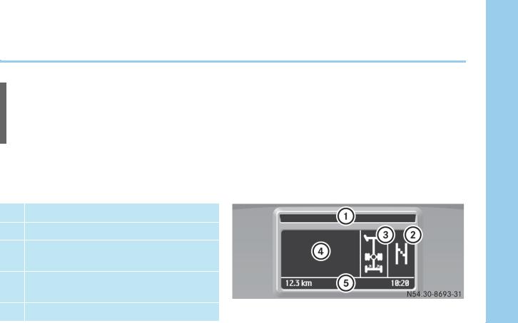
Display fields
The display fields are actuated according to the installed equipment or the activated functions.
1Status indicator
2Gear indicator
3Operating display for differential locks, PTOs and additional axles
4Field for display messages, system abbreviations/fault symbols and fault type
5Information display
Status indicator
Individual segments of the status indicator 1 light up yellow or red to distinguish display messages according to their priority rating. Display messages with yellow/red status indicator, see page 27.
Display messages
Display messages are operating information, faults or warnings that appear automatically in the display, see page 27.
System abbreviation or fault symbol
When a display message is shown on the Plus onboard computer due to a fault, the display shows the system abbreviation of the affected control unit or a fault symbol, e.g. if the coolant temperature is excessively high. System abbreviations, see page 42.
Information display
The following information is displayed:
•Time
•Alarm clock symbol (if alarm clock is activated)
•Speed for the variable speed limiter c/cruise control d
•Trip mileage
Description and roadside assistance
Guidelines for Breakdown Services (Subject to technical modifications) i |
|
21 |
|
|
|

Description and roadside assistance

 Instrument panel
Menus in detail
i
The number and sequence of the menus depend on the vehicle model and the vehicle equipment. The values given are examples.
Risk of accident |
G |
Operating the onboard computer while driving can distract your attention away from what is happening on the road. You could lose control of the vehicle and cause an accident.
For this reason, only operate the onboard computer when the vehicle is stationary with the parking brake applied.
Calling up the main menu
When the default display or another display from the home menu appears, press control pad „ or º. The list of main menus appears in the display.
Press control pad ‚ or ƒ repeatedly until the desired main menu is highlighted in the display.
Press control pad „ to open the highlighted main menu. Another list of the submenus appears in the display.
Calling up a submenu
Select the main menu.
Another list of the submenus appears in the display.
Press control pad ‚ or ƒ repeatedly until the desired submenu is highlighted in the display.
Press control pad „ to open the highlighted submenu.
Another submenu list or the desired display, e.g. Oil level O.K., appears.
Exiting a submenu
Press control pad º.
The next menu up appears in the display.
To go directly to the home menu:
Hold down control pad º for about 2 seconds. The default display appears.
22 iGuidelines for Breakdown Services (Subject to technical modifications)

Instrument panel 
Home menu
The home menu follows a circular pattern and contains the following displays, depending on the vehicle equipment:
•Default display with speed
•Date display
•Info display
•Trip computer
•Radio
•Navigation
Press control pad ‚ or ƒ repeatedly until the desired display appears.
Description and roadside assistance
Guidelines for Breakdown Services (Subject to technical modifications) i |
|
23 |
|
|
|

Description and roadside assistance

 Instrument panel
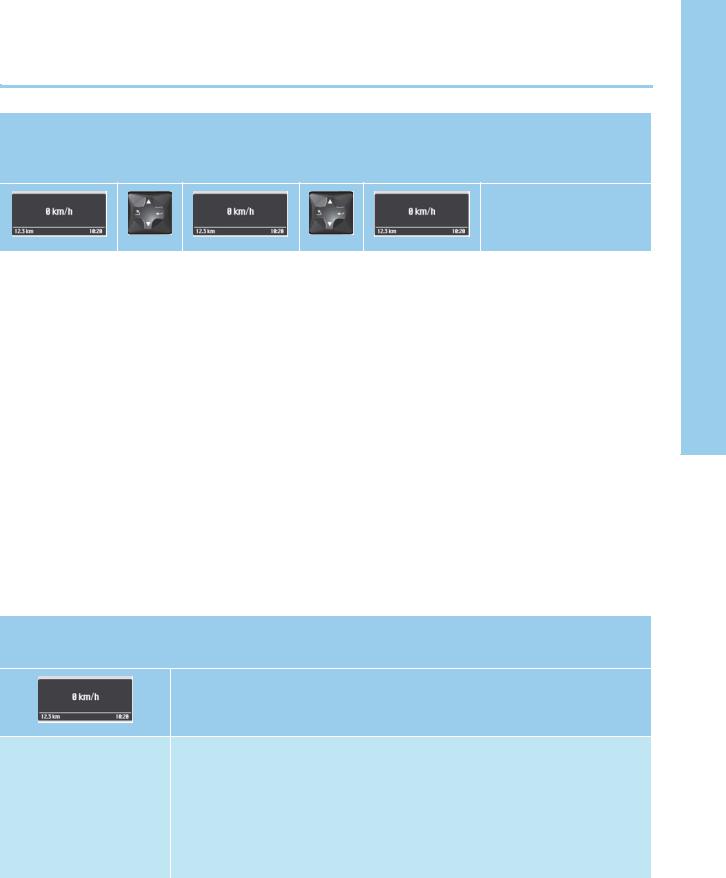
Default display
1Speed display
2Time
3Trip mileage
Main menus and submenus
The various main menus each comprise a number of functions pertaining to the same subject. In the Check Info main menu, the submenus Reservoir pressure, Oil level, Axle load indicator etc. can be displayed.
The following main menus and submenus can be selected:
Check Info |
AdBlue tank |
see page 25 |
|
Driver data |
|
|
Reservoir pressure |
see page 25 |
|
Oil level |
see page 25 |
|
Axle load indicator |
|
|
Operating hours |
|
|
Cargo |
|
|
Trailer ID |
|
Fault Info |
|
see page 25 |
Alarm Clock |
Wakeup mode |
|
|
Wakeup time |
|
Language |
|
|
Settings |
Display differential locks? |
|
|
Time |
|
|
Cargo temperature |
|
|
Cargo pressure |
|
|
Cargo fluid |
|
|
Temperature unit |
|
Service Info |
Engine |
|
|
Condensation |
see page 26 |
Diagnosis |
Control unit list: BS, FR ... |
see page 26 |
|
Erase all events |
see page 26 |
|
|
|
24 iGuidelines for Breakdown Services (Subject to technical modifications)
Instrument panel 
Check Info menu
Call up home menu („ º), Check Info main menu (‚ ƒ and „), and submenu (‚ ƒ).
Description
AdBlue tank |
„ " AdBlue |
- |
- |
The tank content is |
||
|
|
tank 28 l |
|
|
displayed as a bar graph. |
|
Reservoir |
„ |
• |
Tractor |
‚ 1: 6.3 bar |
1 = Reservoir pressure, |
|
pressure |
|
• |
vehicle |
ƒ 2: 6.2 bar |
brake circuit 1 |
|
|
|
Trailer |
and |
|
2 = Reservoir pressure, |
|
|
|
(The menu is only |
|
|||
|
|
„ |
|
|||
|
|
displayed when a |
|
brake circuit 2 |
||
|
|
|
|
|||
|
|
trailer is detected |
|
|
The reservoir pressures |
|
|
|
by the system.) |
|
|
||
|
|
|
|
are displayed as bar |
||
|
|
|
|
|
|
|
|
|
|
|
|
|
graphs. |
Oil level |
„ |
Oil level O.K. |
- |
- |
Check engine oil level with |
|
|
|
or Oil 2.5 l |
|
|
engine at operating |
|
|
|
|
|
|
|
temperature about |
|
|
|
|
|
|
1 minute after switching |
|
|
|
|
|
|
off. |
|
|
|
|
|
|
Top up engine oil if |
|
|
|
|
|
|
necessary. |
|
|
|
|
|
|
|
Fault Info menu
Call up home menu („ º) and Fault Info main menu (‚ ƒ and „).
Description
e.g. bulb/fuse defective If a fault message was stored, it can be displayed in the Fault Info menu. Display messages, see page 27.
If the symbol „ is also shown in the display, this indicates that further information or instructions are available.
Press control pad „.
Further information or instructions are displayed.
Description and roadside assistance
Guidelines for Breakdown Services (Subject to technical modifications) i |
|
25 |
|
|
|

Description and roadside assistance

 Instrument panel
Service Info menu
Call up main menu („ º) and Service Info main menu (‚ ƒ and „).
Description
RESET condensation? The RESET condensation? submenu only appears in conjunction with a relevant display message, see page 27. In some cases the condensation message can be reset by pressing the Reset button. When reset, the message O.K. appears in the display.
Diagnosis menu
Call up home menu („ º), Diagnosis main menu (‚ ƒ and „), and submenu (‚ ƒ).
Description
Control unit list: |
‚ • |
MB object |
‚ MBS 0004464833 |
MB object number/Binary |
|||
• |
BS |
ƒ |
|
number |
ƒ |
values/Measurements: |
|
and |
• |
Events |
and |
These menus contain |
|||
• |
FR |
||||||
• |
Measurements |
||||||
„ |
„ |
information that can be |
|||||
• |
INS |
||||||
• |
Binary values |
||||||
• ... |
|
• |
Erase all |
|
used to ascertain the |
||
|
|
|
|
cause of a fault in a system |
|||
|
|
|
|
events |
|
||
|
|
|
|
|
|
by remote diagnosis. |
|
|
|
|
|
|
|
Events: This menu |
|
|
|
|
|
|
|
contains any existing |
|
|
|
|
|
|
|
display messages from the |
|
|
|
|
|
|
|
system selected. |
|
Erase all events |
„ Yes/No |
‚ - |
All display messages are |
||||
|
|
|
|
|
ƒ |
erased. |
|
|
|
|
|
|
and |
|
|
|
|
|
|
|
„ |
|
|
|
|
|
|
|
|
|
|
26 iGuidelines for Breakdown Services (Subject to technical modifications)

Instrument panel 
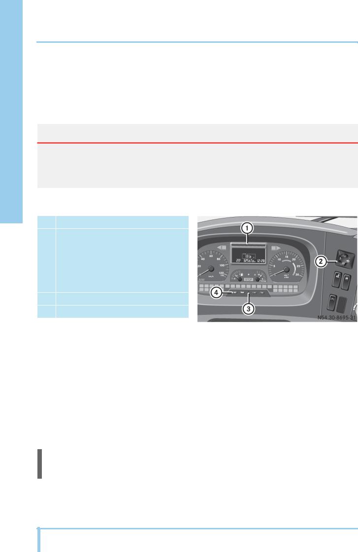
Display messages
Display messages are operating information, fault messages or warnings that appear automatically in the display. The segments of the status indicator light up yellow or red depending on the priority rating. In addition to the display message, an indicator lamp in the instrument panel may light up.
Display messages can be canceled and called up at a later time. If an indicator lamp lights up with the display message, it will not go out again even when the display message is confirmed.
In the case of significant malfunctions, the display message is backed up by a warning buzzer and the STOP lamp.
Display messages in the Standard onboard computer
1Fault Info menu
2System abbreviations
3Fault symbol for cause
Display messages in the Plus onboard computer
1Display message, e.g. bulb/fuse defective
2Call up further information with control pad
„
3Fault location (tractor vehicle or trailer/ semitrailer)
4Fault symbol for cause
Status indicator
1Status indicator
Description and roadside assistance
Guidelines for Breakdown Services (Subject to technical modifications) i |
|
27 |
|
|
|

Description and roadside assistance

 Instrument panel
Confirm display message
Press control pad º.
The display message disappears from the display.
Standard onboard computer: The display message is stored in the diagnosis memory or in the Fault Info menu.
Plus onboard computer: The display message can be called up at any time through the Fault Info menu (see page 25).
Status indicator
Individual segments of the status indicator light up yellow or red to distinguish display messages according to their priority rating.
The status indicator lights up yellow for malfunctions of low priority, e.g. when a bulb is defective. The status indicator also lights up yellow in particular operating states, e.g. when a power take-off has been activated.
The status indicator lights up red for malfunctions of high priority, e.g. when the alternator is defective.
Display message with yellow status indicator
Risk of accident |
G |
The operational safety of the vehicle may be compromised if there is a display message with yellow status indicator.
Adjust your driving style accordingly and drive with special care.
Follow the instructions and observe the additional information in the display.
Have the cause checked and repaired as quickly as possible at a qualified specialist workshop possessing the required expertise and tools in order to perform the necessary work.
Mercedes-Benz recommends a Mercedes-Benz service center for this work. It is absolutely essential that all safety-relevant work and all work on safety-relevant systems is performed by a qualified specialist workshop.
28 iGuidelines for Breakdown Services (Subject to technical modifications)
 Loading...