


OM 457 LA
Table of contents
 Loading...
®
OM 457 LA BlueTec
OM 460 LA BlueTec
Operating Instructions
/ OM 457 LA
®
/ OM 460 LA

Symbols
WARNING
G
Warning notes make you aware of dangers
which could pose a threat to your health or
life, or to the health and life of others.
Environmental note
H
Environmental notes provide you with information on environmentally aware actions or
disposal.
Notes on material damage alert you to
!
dangers
that could lead to damage to your
vehicle.
These symbols indicate useful instruc-
i
tions or further information that could be
helpful to you.
X
This symbol designates an instruction you must follow.
X
Several consecutive symbols indicate an instruction with several
steps.
(Y page)
This symbol tells you where you
can find further information on a
topic.
Y Y
This symbol indicates a warning or
an
instruction that is continued on
the next page.
Display
This text indicates an indicator in
the display.

Welcome
Familiarise yourself with your engine system
and read the operating instructions before
use the engine system. This will help you
you
to avoid endangering yourself or others.
The standard equipment and product description of your engine system may vary, depending on individual specifications. This is described on the data card.
The engine systems are constantly updated
to be state of the art.
Mercedes-Benz reserves the right to make
changes to the following:
R
design
R
equipment
R
technical features
Descriptions may therefore differ in individual
cases from your engine system.
4605843681
É460584
3681ÇËÍ


Contents
3
Index ....................................................... 4
Introduction ........................................... 7
At a glance ........................................... 13
Safety ................................................... 29
Transport, installation ........................ 33
Operation ............................................. 37
Maintenance ........................................ 63
Decommissioning ............................... 75
Troubleshooting .................................. 79
Technical data ..................................... 93

Index
4
A
AdBlue®/DEF
Components
.................................... 18
Consumption ................................... 58
Gauge .............................................. 45
Important safety notes .................... 60
Refuelling ......................................... 60
Service product ............................... 71
ADM (FR (drive control) unit) ............. 14
B
Battery (vehicle)
Jump starting ...................................
83
Bio-diesel fuel
see FAME fatty acid methyl ester fuel
Bleeding the fuel prefilter with the
manual fuel pump ............................... 83
BlueTec
®
Sensors ............................................ 18
Braking
Continuous brake ............................ 41
Engine brake .................................... 41
Retarder ........................................... 42
C
Capacities ............................................
98
Care products ...................................... 72
Charge current .................................... 42
Checking the fluid level ...................... 38
Cleaning and care
Engine cleaning ................................ 73
High-pressure cleaning .................... 72
Notes on care .................................. 72
Cold-start aid ....................................... 61
Consumption
AdBlue®/DEF .................................. 58
Fuel .................................................. 58
Oil (engine) ...................................... 58
Continuous brake
Important safety notes .................... 41
Coolant
Mixing ratio ...................................... 68
Service product ............................... 68
Topping up ....................................... 39
Coolant additive .................................. 68
Correct use ............................................
Corrosion inhibitor/antifreeze
agent .................................................... 68
D
Data card ..............................................
DEF/AdBlue
®
94
see AdBlue®/DEF service products
Description of the engine ................... 14
Diagnostics connection ...................... 31
Diesel
Fuels ................................................ 68
Low outside temperatures ............... 70
Refuelling ......................................... 59
Sulphur content table ...................... 69
Dimensions .......................................... 95
Disposal of service products .............. 65
Driving mode
Idling speed ..................................... 42
Driving tips .......................................... 58
E
Electronic engine control
see Engine management
Electronic engine control unit ............
42
Emergency gearshift
Using the emergency switch ............ 44
Emergency running program ................ 8
Engine
Capacities ........................................ 98
Cleaning ........................................... 72
Data ................................................. 95
Data card ......................................... 94
Data plate ........................................ 94
Modifying the power output ............... 8
Oil consumption ............................... 58
Operating data ................................. 97
Rectifying faults ............................... 86
Running-in period ............................. 58
Starting ............................................ 39
Stopping .......................................... 40
Engine brake ........................................ 41
Engine data .......................................... 95
Engine data card .................................. 94
Engine description .............................. 14
Engine idling speed ............................. 42
8

Index
5
Engine management ...........................
Engine management control unit ...... 20
Engine model designation .................. 94
Engine oil
Consumption ................................... 58
For winter operation ........................ 65
Mixing .............................................. 67
Oil change ........................................ 66
Topping up ....................................... 67
Engine overview .................................. 15
Engine speed ....................................... 44
Exhaust gas aftertreatment ............... 21
Exhaust gas aftertreatment con-
trol unit ................................................ 21
19
F
FR (drive control) unit
see ADM
Fuel
Additives ..........................................
Consumption ................................... 58
Diesel ............................................... 68
FAME fatty acid methyl ester fuel .... 70
Refuelling ......................................... 59
Sulphur content table ...................... 69
Fuel grade ............................................ 69
Fuel prefilter
Draining ........................................... 82
Fuel system
Automatic bleeding .......................... 81
Manual bleeding .............................. 81
Fuses
Checking and replacing a safety
fuse .................................................. 83
Important safety notes .................... 83
70
G
Gauge
AdBlue®/DEF .................................. 45
Genuine Mercedes-Benz parts ............. 7
Getting started .................................... 80
H
High-pressure cleaning .......................
72
I
Identification plate ..............................
Idling speed
Engine .............................................. 42
Indicator and warning lamps
BlueTec® exhaust gas aftertreat-
ment ................................................ 24
Installation ........................................... 34
Instrument cluster
Warning and indicator lamps ........... 23
94
J
Jump-starting .......................................
83
M
Maintenance
............................................... 64
Notes
Mercedes-Benz Service Centre
see Qualified specialist workshop
MR control unit
see Engine management control unit
O
Oil (engine)
For winter operation
Oil change ........................................ 66
Scope of use .................................... 66
Oil pressure ......................................... 42
Operating data ..................................... 97
Operating instructions
General notes .................................. 10
Operating restriction
Off-highway ...................................... 26
On-highway ...................................... 24
Operating safety .................................. 30
Operating safety and registration
Changes in engine performance ........ 8
Implied warranty ................................ 8
Operational monitoring ...................... 42
Organisational measures ................... 31
Overview, sensors ............................... 17
........................ 65
P
Personnel .............................................
31

Index
6
Poly-V-belt
Replacing
Routing ............................................ 90
Preparing for starting operation
see Starting operation
Protection of the environment ............. 7
......................................... 90
Q
Qualified specialist workshop ...........
10
R
Refuelling
AdBlue®/DEF
Fuels ................................................ 59
Requirements of the personnel ......... 31
Rev counter .......................................... 44
Roadside Assistance ........................... 80
Running the vehicle in ........................ 58
.................................. 60
S
and emergency running pro-
Safety
gram ....................................................... 8
Safety precautions .............................. 30
SCR frame module
see Exhaust gas aftertreatment
control unit
Service products
AdBlue®/DEF .................................. 71
Coolant ............................................ 68
DEF/AdBlue® .................................. 71
Diesel fuel ........................................ 68
Disposal ........................................... 65
Disposing of AdBlue®/DEF .............. 72
Engine oil ......................................... 65
FAME fatty acid methyl ester fuel .... 70
Fuel additives ................................... 70
General notes .................................. 65
Purity of AdBlue®/DEF .................... 72
Storing AdBlue®/DEF ...................... 72
Specialist workshop ............................ 10
Starting
see Starting (engine)
Starting (engine) .................................. 39
Stopping and switching off the
engine ................................................... 39
Sulphur content of fuel .......................
69
T
Technical data
Dimensions
Filling capacities .............................. 98
Operating data ................................. 97
Weights ............................................ 95
Tightening torques .............................. 99
Torque reduction ................................. 43
Transport .............................................. 34
...................................... 95
W
Warning and indicator lamps
Electronics
Weights ................................................ 96
Winter diesel ........................................ 70
Winter operation ................................. 61
....................................... 46

Introduction
7
Engine system
The OM 457-460 LA BlueTec® series of
engines
only function as intended when used
in conjunction with the corresponding
exhaust gas aftertreatment unit. Therefore, in
these Operating Instructions, the term
"engine system" refers to the engine and the
exhaust gas aftertreatment unit.
Protection of the environment
Environmental note
H
Daimler AG has a declared policy of comprehensive environmental protection.
The objectives are to use the natural resources which form the basis of our existence on
this planet sparingly and in a manner which
takes the requirements of both nature and
humanity into account.
You too can help to protect the environment
by operating your vehicle in an environmentally responsible manner.
Information and notes on driving in an environmentally
responsible and fuel-saving manner can be found in the "Operating notes"
section (Y page 58).
Assembly equipment
These Operating Instructions describe all
models and all standard and optional equipment available for your engine system at the
time of publication of the Operating Instructions. Country-specific deviations are possible.
Note that your engine system may not be
fitted with all features described. This also
applies to safety-relevant systems and functions. Therefore, the equipment on your
engine system may differ from certain
descriptions and illustrations.
All of the components in your engine system
are listed in the data card of your engine system. Data card (Y page 94).
Please contact a Mercedes-Benz, MTU or
MTU-authorised Mercedes-Benz Service
Centre
if you have any questions about equipment or operation (see addresses in the publication details on the rear inside cover).
R
Mercedes-Benz recommends, for on-highway applications, that you use a MercedesBenz Service Centre.
R
MTU recommends, for off-highway applications, an MTU partner or MTU-authorised
Mercedes‑Benz partner.
Genuine Mercedes-Benz parts
Environmental note
H
Daimler AG also supplies reconditioned
assemblies and parts which are of the same
as new parts. For these, the same war-
quality
ranty applies as for new parts.
If you use parts which have not been
approved by Mercedes-Benz, the operational
safety of the engine system may be jeopardised. This could lead to malfunctions in
safety-relevant systems. Use only genuine
Mercedes-Benz parts or parts of equal quality. Only use parts that have been approved
for your engine type.
Mercedes-Benz checks genuine MercedesBenz parts for:
R
reliability
R
safety
R
suitability
Despite ongoing market research, MercedesBenz is unable to assess other parts.
Mercedes-Benz therefore accepts no responsibility for the use of such parts in MercedesBenz vehicles, even if they have been officially
approved or independently approved by a
testing centre.
In Germany, certain parts are only officially
approved for installation or modification if
they comply with legal requirements. This
also applies to some other countries. All genuine Mercedes-Benz parts meet the approval
Z

Introduction
8
requirements. The use of non-approved parts
may
invalidate the vehicle's general operating
permit.
This is the case if:
R
they result in a change to the vehicle type
from that for which the vehicle's general
operating permit was granted
R
they pose a possible risk for road users
R
they adversely affect the emission or noise
levels
You can find more information on recommended conversion parts and accessories, as well
as permitted technical modifications at any
Mercedes-Benz, MTU or MTU-authorised
Mercedes-Benz Service Centre (Y page 10).
Always state the engine number when ordering genuine Mercedes-Benz parts. You can
find the engine number on the identification
plate of your engine. You can also find the
numbers on the data card (Y page 94).
Modifying the engine output
Increased power could:
!
R
change emission levels
R
cause malfunctions
R
lead to consequential damage
The operating safety of the engine cannot
be guaranteed in all situations.
Any tampering with the engine management
in order to increase the engine power
system
output will lead to a loss of warranty entitlements.
Safety/emergency running program
If the electronic control system detects a malfunction, one of the following measures is
automatically
implemented after an appraisal
of the malfunction:
R
faults during operation are indicated by the
corresponding warning lamp (Y page 46).
R
in conjunction with the electronic engine
management system, fault codes with additional information can be shown on a display.
R
the system switches to a suitable backup
function for the continued, albeit restricted, operation of the engine. This includes
torque and engine speed limitation, for
example, as well as road speed limitation or
constant emergency running speed.
Correct use
The engine system may only be installed as
contractually specified.
The manufacturer of the end product is
responsible
for the correct installation of the
engine and the exhaust gas aftertreatment
system in the overall system.
The engine and the exhaust gas aftertreatment system may not be modified. If the
engine is modified, Mercedes-Benz and MTU
do not accept responsibility for any damage
arising as a result.
Correct use of the engine system also
requires adherence to the instructions in
these Operating Instructions. This also
requires compliance with the maintenance
intervals and the professional execution of
maintenance work. Please observe the Workshop Information System (WIS) (Y page 10).
The engine is equipped with an electronic
engine management system that monitors
the engine and has a self-diagnostic system.
Implied warranty
well-developed network of Mercedes-Benz,
A
MTU and MTU-authorised Mercedes-Benz
Service Centres is available to carry out maintenance work.

Introduction
9
These Mercedes-Benz and MTU or MTUauthorised Mercedes-Benz Service Centres:
R
have
special equipment and tools as well as
specialists who receive continuous training
R
guarantee that your engine system is
repaired and maintained thoroughly and
expertly
R
carry out all repairs related to implied warranty
R
carry out all maintenance work expertly
R
confirm in the Maintenance Booklet that
the maintenance work has been carried out
at the required time
R
handle implied warranty claims that are
admissible according to the sales contract
Please observe the instructions and recommendations as well as the maintenance services in the Maintenance Booklet. Please
observe these instructions even if you let a
third party use and care for your vehicle. This
is the only way to ensure that you do not lose
your entitlements.
If the prescribed maintenance work is not
carried out, claims can only be decided after
the manufacturer has inspected the claim.
During the implied warranty period, have the
prescribed maintenance service for your
engine system carried out as follows:
R
regularly
R
punctually
R
at a qualified specialist workshop which
has the necessary specialist knowledge
and tools to carry out the work required
Mercedes-Benz recommends that you use
a Mercedes-Benz, MTU or MTU-authorised
Mercedes-Benz Service Centre. In particular, work relevant to safety or on safetyrelated systems must be carried out by a
qualified specialist workshop.
If there are legal requirements on emission
control, please note that:
R
maintenance on the engines must be carried out according to specific regulations
and using special measuring devices
R
it is prohibited to modify or tamper with
components relevant to emissions
All Mercedes-Benz and MTU or MTU-authorised Mercedes-Benz Service Centres are
familiar with the relevant regulations.
Maintenance work does not include repair
work. Issue a separate order for repair work.
You can obtain further information on the
maintenance of your engine system from any
Mercedes-Benz, MTU or MTU-authorised
Mercedes-Benz Service Centre.
Stored data
Several
of the electronic components in your
engine system contain data memories.
These data memories temporarily or permanently store technical information about:
R
the engine system state
R
events
R
malfunctions
In general, this technical information documents the state of a component, a module, a
system or the surroundings.
This includes, for example:
R
operating conditions of system components, e.g. fluid levels
R
the vehicle's status messages and those of
its individual components, e.g. speed,
deceleration in movement, accelerator
position
R
malfunctions and defects in important system components
R
the vehicle's reactions and operating statuses in special driving situations
R
ambient conditions, e.g. outside temperature
Z

Introduction
10
This data is exclusively technical in nature
and can be used to:
R
assist in the detection and rectification of
faults and defects
R
analyse
vehicle functions, e.g. after an acci-
dent
The data cannot be used to trace the vehicle's
movements.
When you use one of the available services,
technical information may be read from the
event data memory and fault data memory.
Services include, for example:
R
repair services
R
service processes
R
implied warranty and guarantee cases
R
quality assurance
The information is read out by employees of
the service network (including manufacturers) using special diagnostic testers. Further
information is available there if required.
After a fault has been rectified, the information is deleted from the fault memory or is
continually overwritten.
Qualified specialist workshop
A qualified specialist workshop has the necessary specialist knowledge, tools and qualifications
to carry out the work required on the
engine to a professional standard. This is particularly applicable to work relevant to safety.
Observe the notes in the Maintenance Booklet.
Always have the following maintenance work
carried out at a qualified specialist workshop:
R
work relevant to safety
R
service and maintenance work
R
repair work
R
modifications as well as installations and
conversions
R
work on electronic components
R
Mercedes-Benz recommends, for on-highway
applications, that you use a Mercedes-
Benz Service Centre.
R
MTU recommends, for off-highway applications, an MTU partner or MTU-authorised
Mercedes‑Benz partner.
Further applicable documents
These Operating Instructions describe all
models, as well as all standard and optional
equipment of your engine system which are
part of the scope of delivery of Daimler AG.
installation of the engine system into the
The
vehicle/device may require additional operating instructions adapted to the vehicle/
device and the appropriate use thereof. These
additional operating instructions will be provided by the vehicle/device manufacturer.
The additional operating instructions will
describe, in particular, the functions specific
to the installation and operation, the use of
such functions as well as warning and control
mechanisms.
To use the engine correctly, you also require
the Maintenance Booklet.
For US-certified off-highway engines you also
require the "Emission Warranty" supplement.
Please also observe the information contained in the vehicle or the equipment operating instructions (manufacturer of the end
product). Always keep these documents
together with the engine, vehicle or equipment. These documents should be passed on
to the new owner if you sell the engine, vehicle or equipment.
When carrying out maintenance work, you
require access to the Workshop Information
System (WIS) via the Internet. This access is
subject to a fee.
Current information on the system and prices
can be found at this web address: http://
service-parts.mercedes-benz.com. Click on
"EPC, WIS/ASRA" in the "Service and parts
information" tab and then on "WIS".

You can log in by clicking on "Register" on the
right-hand side.
Introduction
11
Z

12

General information ............................ 14
Engine overview .................................. 15
Sensors overview ................................ 17
Electronic engine management ......... 19
BlueTec® exhaust gas aftertreat-
ment ..................................................... 21
Warning and indicator lamps ............. 23
13
At a glance

General information
14
General information
engine is a four-stroke, water-cooled die-
The
sel engine with direct injection.
The six cylinders are arranged in a row. Each
cylinder has two inlet and two outlet valves.
Each cylinder has its own fuel injection pump
(unit pump) with a short high-pressure fuel
At a glance
injection line to the multi-hole nozzle at the
centre of the combustion chamber. The unit
pumps sit directly in the crankcase and are
driven by the camshaft.
The engine is equipped with exhaust gas turbocharger and intercooler as standard. The
engine may include an engine brake (airbrake
and constantly open throttle) as optional
equipment.
It is a low-emission engine. Start of injection,
injection duration and injection quantity are
controlled entirely electronically.
BlueTEC® exhaust
The engines meet the requirements of the
relevant emissions level and are correspondingly certified. Compliance with emissions
laws and regulations is a condition of the
operating permit for the vehicle/equipment.
The BlueTEC® exhaust gas aftertreatment
unit is characterised by the following technologies:
R
selective catalytic reduction (SCR) with
ammonia slip catalytic converter
R
the diesel oxidation catalytic converter
(DOC)
Engines with BlueTEC® exhaust gas aftertreatment must be operated with AdBlue® or
DEF in order to meet the emissions laws and
regulations. The operating permit is invalidated if the vehicle/equipment is operated
without AdBlue®/DEF. Failure to use
AdBlue® or DEF during operation may be a
statutory or regulatory offence in certain
countries. Special concessions granted
either at the time of purchase or to reduce
gas aftertreatment
operating costs of the vehicle/equipment,
e.g. reduced taxes or tolls, may also be rendered retroactively invalid. This may be the
case in the country of registration. Or also in
another country where you operate the vehicle/equipment.

Engine overview
Engine overview
15
At a glance
:
Poly-V-belt
;
Fuel pump
=
Thermostat housing
?
Fuel filter
A
Oil filter
B
Cylinder head cover
C
Start/Stop button
D
Charge-air distributor
E
Charge-air pipe from the charge-air cooler
F
Crankcase ventilation system
G
Engine control unit (MR)
H
Air compressor
I
Power-steering pump
J
Dipstick
K
Engine oil filler neck

Engine overview
16
At a glance
:
Alternator
;
Starter motor
=
Exhaust gas turbocharger
?
Exhaust manifold
A
Coolant pump
B
Poly V-belt tensioning device

Sensors overview
Sensors, general
Sensors overview
17
At a glance
:
Engine oil pressure and temperature sensor
;
Charge-air pressure/temperature sensor
=
Camshaft position sensor (on camshaft gear)
?
Crankshaft position sensor (on flywheel)
A
Coolant temperature sensor
B
Engine oil level sensor
C
Fuel temperature sensor

Sensors overview
18
AdBlue®/DEF components
At a glance
BlueTec® sensors, overview
:
NOX sensor
;
Metering unit
=
Exhaust aftertreatment unit
?
Temperature and humidity sensor (air filter, clean air side)
A
Valve preheating, AdBlue®/DEF system
B
Exhaust gas temperature sensor (inlet)
C
Exhaust gas temperature sensor (outlet)
D
Exhaust gas aftertreatment control unit
E
Supply unit
F
AdBlue®/DEF filter
G
AdBlue®/DEF tank
Electronic engine management
19
At a glance
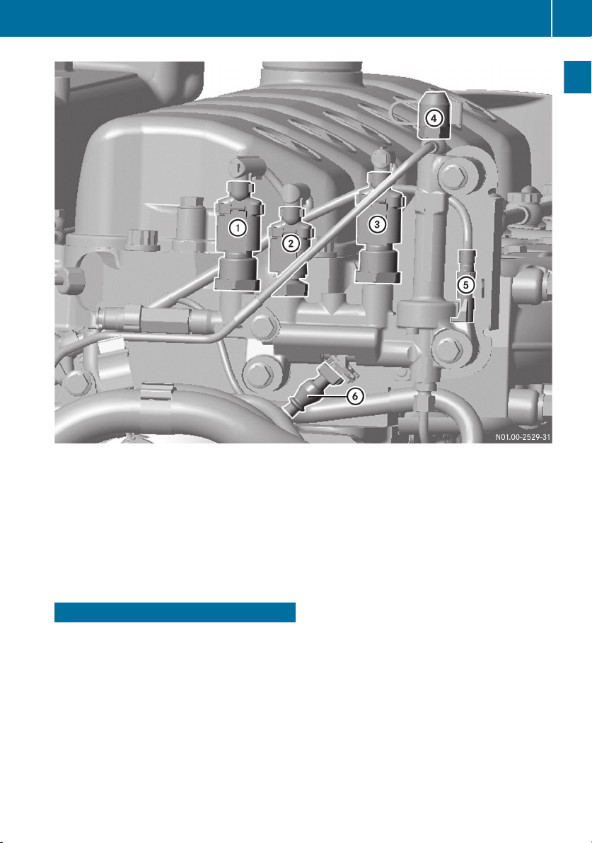
BlueTec® sensors and test connection on the metering unit
:
AdBlue®/DEF pressure sensor
;
AdBlue®/DEF temperature sensor
=
Pressure sensor for compressed air
?
Metering unit test connection
A
Metering unit heater
B
Metering valve
R
Electronic engine management
The engine system is equipped with an electronic engine management system which
comprises the following control units:
R
engine control unit (MR)
R
drive control unit (ADM)
R
exhaust gas aftertreatment control unit
(only for engines with BlueTec® exhaust
gas aftertreatment)
The electronic engine management system
monitors:
the engine
R
the
of BlueTec
R
and, as well as the connection to the vehicle or the device, it also monitors itself.
Depending on the malfunctions or failures
which occur, warning and information displays are activated (Y page 23). The malfunction is stored in the fault memory and if
necessary a safety and emergency mode is
automatically selected (Y page 42). If the
electronic engine management control
exhaust gas aftertreatment in the case
®

Electronic engine management
20
detects a fault, the fault code is stored in the
control
units. It can then be read by a qualified
specialist workshop (Y page 10) using a diagnostic tester.
Engine management control unit (MR) (engine-mounted)
At a glance
The engine management control unit (MR) is
on the side of the engine.
Start of injection, injection duration and injection quantity are calculated on this basis and
the unit pumps are controlled via the solenoid
valve accordingly.
If BlueTec® exhaust gas aftertreatment is
available, the associated sensors are also
analysed and the AdBlue®/DEF dosage is
controlled.
To obtain a replacement engine manage-
i
ment control unit (MR), you will require all
the data on the control unit type plate.
Example: engine management control unit (MR)
The engine management control unit (MR)
processes values from the drive control unit
(ADM).
These are, for example, the position of
the accelerator pedal sensor, the engine
brake or engine start/stop, etc.
These values are analysed together with data
from the engine sensors. They are compared
with the charts or characteristic curves
stored in the engine management control unit
(MR).
Data from the sensors derives from information such as:
R
charge-air pressure and charge-air temperature
R
coolant temperature
R
fuel temperature
R
oil pressure
Control unit type plate
:
Data record
;
Certification no.
=
Engine number
?
Equipment code
Drive control unit (ADM)
The drive control unit (ADM) is installed in a
protected location in the vehicle/device by
the vehicle/device manufacturer. It acts as
an interface between the electric and electronic components on the vehicle/device
side and the engine management control
module (MR) on the engine side.
The engine can be adapted to the various
operation-specific requirements using the
drive control unit (ADM).

BlueTec® exhaust gas aftertreatment
Example: drive control unit (ADM)
The drive control unit (ADM) has many functions:
R
Calculation of torque demand
The drive control unit (ADM) registers the
driver's requirements. For example, the
position of the accelerator is detected by
the drive control unit (ADM). A torque
requirement is calculated from that and
sent to the engine management control
module (MR) via the CAN connection.
In doing so, information and limitations
from optionally connected control units
such as the gearbox control, retarder control, ABS and ASR are taken into account.
R
Output of displays and indicator signals
which
are displayed in the instrument clus-
ter.
R
Monitoring of coolant level, charge current
and air filter, for example
R
Legal speed limitation
R
Evaluation of start request
The engine starting process is initiated
once a corresponding start request is present (ignition lock or external engine start/
engine stop button).
Exhaust gas aftertreatment control unit (on the frame)
Exhaust gas aftertreatment control unit
The exhaust gas aftertreatment control unit
reads
signals and transmits them via the CAN
line to the engine management (MR) control
unit.
The following signals are read:
R
temperature sensor upstream of the SCR
catalytic converter
R
temperature sensor downstream of the
SCR catalytic converter
R
NOx sensor downstream of the SCR catalytic converter
R
pressure and temperature sensor for the
fluid level and temperature in the AdBlue®/
DEF tank
R
sensor for humidity and intake air temperature
If the electronic engine management control
detects a fault, the fault code is stored in the
control units.
BlueTec® exhaust gas aftertreatment
21
At a glance
The exhaust gas aftertreatment system is
activated
immediately after the engine is started and remains activated during engine
operation. It ensures that the pollutant emissions in the exhaust gas are reduced to the
limits stipulated in the emissions standard.

22
BlueTec® exhaust gas aftertreatment
Exhaust gas treatment is carried out by:
R
selective catalytic reduction (SCR) with
ammonia slip catalytic converter
R
the diesel oxidation catalytic converter
(DOC)
In order to ensure correct operation of the
BlueTec®
At a glance
only operate the engine, vehicle or device
with AdBlue®/DEF reducing agent. AdBlue®/
DEF is not refilled as part of the maintenance
work. You should therefore top up the
AdBlue®/DEF tank regularly.
Mercedes-Benz recommends that you use a
Mercedes-Benz or MTU Service Centre.
BlueTec® technology is one part of the engine
homologation that requires certification.
Operating the engine, vehicle or device without AdBlue®/DEF or with another medium
that has not been approved by Daimler invalidates the engine's operating permit or certification.
exhaust gas aftertreatment system,
Continuous brake
If increased braking power is required, the
engine can be equipped with a brake valve
downstream from the exhaust gas turbocharger
valves. The brake valve uses exhaust back
pressure to increase braking power. The constant throttle valves bring about a reduction
of the compression pressure in the power
stroke (third stroke), whilst the compression
(second stroke) is not significantly affected.
The constant throttle valve is an additional
valve in the cylinder head. When open, the
constant throttle valve establishes a connection between the combustion chamber and
exhaust port.
in conjunction with constant throttle

Warning and indicator lamps
Warning and indicator lamps
Important safety notes
Important safety notes
If you ignore warning and indicator lamps, you will not be able to recognise failures and malfunctions
the road and operating safety of your vehicle or equipment may be restricted. Have the affected system checked and repaired at a qualified specialist workshop. Always observe the
warning and indicator lamps and follow the corresponding corrective actions (Y page 46).
Overview
The indicator and warning lamp display is designed for the specific vehicle or equipment.
Please also observe the information in the additional operating instructions. These will be
provided
their appearance may differ in the vehicle or on the equipment. In the event of a fault or
warning, a warning lamp or indicator lamp lights up automatically. Depending on the priority of
the fault or warning, the warning and indicator lamps light up in different combinations. The
following warning and indicator lamps may be available on the instrument panel:
in components or systems. The driving and braking characteristics may change and
by the vehicle/device manufacturer. The symbols listed below are examples only and
23
At a glance
On-highway version without BlueTec
®1
The following warning and indicator lamps may be available on the instrument panel:
Indicator lamp Description
r red
Ù
#
%
2
Engine stop
Engine system malfunction
Charge current
Cold-start aid
(optional)
5
Oil pressure too low (engine)
(optional)
4
Oil level too low (engine)
(optional)
,
Coolant level too low
(optional)
?
Coolant temperature too high
(optional)
1
On-highway: vehicles with operating permit
2
In addition, an acoustic warning signal may sound.

Warning and indicator lamps
24
Indicator lamp Description
Ã
Continuous brake active
(optional)
é
Cruise control
(optional)
È
At a glance
Speed limiter
(optional)
I
Power take-off engaged
(optional)
On-highway version1 with BlueTec
®
The following warning and indicator lamps may be available on the instrument panel:
Indicator lamp Description
r red
Ù
;
2
Engine stop
Engine system malfunction
Engine diagnostics MIL
s (lit constantly) Torque operating restriction
#
%
Charge current
Cold-start aid
(optional)
Ø
AdBlue®/DEF reserve level
(optional)
5
Oil pressure too low (engine)
(optional)
4
Oil level too low (engine)
(optional)
,
Coolant level too low
(optional)
?
Coolant temperature too high
(optional)
1
On-highway: vehicles with operating permit
2
In addition, an acoustic warning signal may sound.

Indicator lamp Description
Warning and indicator lamps
25
Ã
Continuous brake active
(optional)
é
Cruise control
(optional)
È
Speed limiter
(optional)
I
Power take-off engaged
(optional)
Off-highway version3 without BlueTec
®
The following warning and indicator lamps may be available on the instrument panel:
Indicator lamp Description
r red
Ù
#
%
2
Engine stop
Engine system malfunction
Charge current
Cold-start aid
(optional)
5
Oil pressure too low (engine)
(optional)
At a glance
4
Oil level too low (engine)
(optional)
,
Coolant level too low
(optional)
?
Coolant temperature too high
(optional)
Ã
Continuous brake active
(optional)
é
Cruise control
(optional)
3
Off-highway: devices/vehicles
2
In addition, an acoustic warning signal may sound.

Warning and indicator lamps
26
Indicator lamp Description
È
Speed limiter
(optional)
I
Power take-off engaged
(optional)
At a glance
Off-highway version3 with BlueTec
The following warning and indicator lamps may be available on the instrument panel:
Indicator lamp Description
r red
Ù
·
2
Engine stop
Engine system malfunction
Emissions-relevant malfunction of the exhaust gas aftertreatment system or AdBlue®/DEF supply
s (lit constantly) Torque operating restriction
s (flashing) Torque and engine speed operating restriction
#
%
Charge current
Cold-start aid
(optional)
Ø
AdBlue®/DEF reserve level
(optional)
®
5
Oil pressure too low (engine)
(optional)
4
Oil level too low (engine)
(optional)
,
Coolant level too low
(optional)
?
Coolant temperature too high
(optional)
Ã
Continuous brake active
(optional)
3
Off-highway: devices/vehicles
2
In addition, an acoustic warning signal may sound.

Indicator lamp Description
Warning and indicator lamps
27
é
(optional)
È
(optional)
I
(optional)
Cruise control
Speed limiter
Power take-off engaged
At a glance

28
Loading...