


Introduction of engine OM 471 and exhaust aftertreatment
Introduction into Service Manual
– This printout will not be recorded by the update service. Status: 09 / 2011 –
Mercedes>Benz Service
Introduction of engine OM 471 and exhaust aftertreatment
Technical status 01.09.2011
Daimler AG . Technical Information and Workshop Equipment(GSP/OI)
D$70546 Stuttgart
– This printout will not be recorded by the update service. Status: 09 / 2011 –

Information and copyright
Product portfolio
You can also find comprehensive information about our complete product portfolio on our Internet portal: Link: http://aftersales.mercedes>benz.com
Questions and suggestions
If you have any questions or suggestions concerning this product, please write to us.
E>Mail: |
customer.support@daimler.com |
Telefax: |
+49>(0)18 05/0 10>79 78 |
or alternatively
Address: Daimler AG GSP/OIS,
HPC R822, W002
D>70546 Stuttgart (Germany)
©2011 by Daimler AG
This document, including all its parts, is protected by copyright.
Any further processing or use requires the previous written consent of Daimler AG, Department GSP/OIS, HPC R822, W002, D>70546 Stuttgart.
This applies in particular to reproduction, distribution, alteration, translation, microfilming and storage and/or processing in electronic systems, including databases and online services.
Image no. of title image: |
W00.01>1015>00 |
Order no. of this publication: |
6517 1260 02 > HLI 000 000 02 82 |
09/11 |
|
– This printout will not be recorded by the update service. Status: 09 / 2011 –

Preface
SN00.00>W>0001>01HD Preface
The intention behind this brochure is to introduce you to the new 6>cylinder inline diesel engine OM 471 along with the new exhaust aftertreatment system (EATS).
This brochure is intended for the technical personnel entrusted with the maintenance and repair of Mercedes>Benz trucks.
The content of this brochure is split up into:
• as>built configuration descriptions
• function descriptions
• component descriptions
All the data listed in this brochure correspond with the technical status as per September 2011.
Any changes or supplements hereto will be published in the Workshop Information System (WIS) only.
Additional documents for the OM 471 engine and the EATS, such as maintenance and repair instructions or wiring diagrams are also available in the Workshop Information System (WIS).
Mercedes>Benz
W‘rth plant, GSP/TTM
September 2011
i Introduction of engine OM 471 and exhaust aftertreatment > 09/2011 > |
1 |
– This printout will not be recorded by the update service. Status: 09 / 2011 –

Contents
SN00.00>W>0110HA |
Overview of as>built configuration and function descriptions |
2.8.11 |
|
|
|
ENGINES 471.9 |
|
|
|
Overview of new features |
|
|
|
|
|
|
|
Engine OM!471 |
|
Page 10 |
|
|
|
|
|
Technical data of diesel engine OM 471 |
|
Page 11 |
|
|
|
|
|
|
|
|
|
As>built configuration |
|
|
|
descriptions |
|
|
|
|
|
|
|
Cylinder head cover, as>built configuration |
|
Page 12 |
|
|
|
|
|
Cylinder head, as>built configuration |
|
Page 13 |
|
|
|
|
|
Cylinder head gasket, as>built configuration |
|
Page 18 |
|
|
|
|
|
Crankcase as>built configuration |
|
Page 19 |
|
|
|
|
|
Connecting rod, as>built configuration |
|
Page 21 |
|
|
|
|
|
Piston, as>built configuration |
|
Page 22 |
|
|
|
|
|
Crankshaft, as>built configuration |
|
Page 23 |
|
|
|
|
|
Valve control; as>built configuration |
|
Page 24 |
|
|
|
|
|
Gear drive, as>built configuration |
|
Page 29 |
|
|
|
|
|
Camshaft, as>built configuration |
|
Page 31 |
|
|
|
|
|
Belt drive, as>built configuration |
|
Page 32 |
|
|
|
|
|
|
|
|
|
Function descriptions |
|
|
|
|
|
|
|
|
|
|
|
Crankcase ventilation system function |
|
Page 34 |
|
|
|
|
|
|
|
|
|
Charging, function |
|
Page 35 |
|
|
|
|
|
|
|
|
|
Engine management, function |
|
Page 37 |
|
|
|
|
|
Engine management, overall network |
|
Page 39 |
|
|
|
|
|
Engine management, behavior in the event |
|
Page 40 |
|
of malfunctions |
|
|
|
|
|
|
|
Start procedure, function |
|
Page 42 |
|
|
|
|
|
Idle speed control, function |
|
Page 44 |
|
|
|
|
|
Working speed control, function |
|
Page 46 |
|
|
|
|
|
Driving, function |
|
Page 48 |
|
|
|
|
|
Engine shutoff procedure, function |
|
Page 50 |
|
|
|
|
|
Determination of the engine speed and |
|
Page 53 |
|
crankshaft angle, function |
|
|
|
|
|
|
|
Determination of the compression stroke at |
|
Page 54 |
|
cylinder 1, function |
|
|
|
|
|
|
2
– This printout will not be recorded by the update service. Status: 09 / 2011 –

|
|
|
Contents |
|
|
|
|
|
|
|
Determination of coolant temperature, |
|
Page 55 |
|
|
function |
|
|
|
|
|
|
|
|
|
Determination of air mass, function |
|
Page 56 |
|
|
|
|
|
|
|
Determination of the fuel temperature, |
|
Page 57 |
|
|
function |
|
|
|
|
|
|
|
|
|
Function of the specified engine torque |
|
Page 58 |
|
|
calculation |
|
|
|
|
|
|
|
|
|
|
|
|
|
|
Engine brake, function |
|
Page 60 |
|
|
|
|
|
|
|
|
|
|
|
|
Exhaust gas recirculation, function |
|
Page 66 |
|
|
|
|
|
|
|
|
|
|
|
|
Exhaust aftertreatment, function |
Vehicles with code (M5R) Engine version |
Page 68 |
|
|
|
EEV and vehicles with code (M5Y) Engine |
|
|
|
|
version Euro V |
|
|
|
|
Vehicles with code (M5Z) Engine version |
Page 73 |
|
|
|
Euro VI |
|
|
|
|
|
|
|
|
Exhaust aftertreatment, overall network |
|
Page 79 |
|
|
|
|
|
|
|
|
|
|
|
|
Engine oil circuit, function |
|
Page 80 |
|
|
|
|
|
|
|
Engine oil circuit, diagram |
|
Page 82 |
|
|
|
|
|
|
|
|
|
|
|
|
Coolant circuit, function |
|
Page 83 |
|
|
|
|
|
|
|
Coolant circuit, diagram |
|
Page 86 |
|
|
|
|
|
|
|
|
|
|
|
|
Engine cooling thermal management, |
i Only in vehicles with code (M7T) |
Page 87 |
|
|
function |
Coolant pump, controlled. |
|
|
|
|
|
|
|
|
Engine cooling thermal management, |
|
Page 90 |
|
|
overall network |
|
|
|
|
|
|
|
|
|
|
|
|
|
|
Fuel supply, function |
|
Page 91 |
|
|
|
|
|
|
|
Fuel low pressure circuit function |
Vehicles with code (M5R) Engine version |
Page 93 |
|
|
|
EEV and vehicles with code (M5Y) Engine |
|
|
|
|
version Euro V |
|
|
|
|
Vehicles with code (M5Z) Engine version |
Page 96 |
|
|
|
Euro VI |
|
|
|
|
|
|
|
|
Fuel high pressure circuit function |
|
Page 100 |
|
|
|
|
|
|
|
|
|
|
|
|
Component descriptions |
|
|
|
|
|
|
|
|
|
|
|
|
|
|
Central gateway control unit (CGW), |
A2 |
Page 101 |
|
|
component description |
|
|
|
|
|
|
|
|
i Introduction of engine OM 471 and exhaust aftertreatment > 09/2011 > |
3 |
– This printout will not be recorded by the update service. Status: 09 / 2011 –

Contents
|
Component description drive control (CPC) |
A3 |
Page 102 |
|
control unit |
|
|
|
|
|
|
|
Component description for engine |
A4 |
Page 103 |
|
management (MCM) control unit |
|
|
|
|
|
|
|
Electronic Brake Control control unit (EBS), |
A10b, A10c |
Page 105 |
|
component description |
|
|
|
|
|
|
|
Parameterizable special module (PSM) |
A22 |
Page 106 |
|
control unit component description |
|
|
|
|
|
|
|
Battery disconnect switch control unit, |
A33 |
Page 107 |
|
component description |
i Only in vehicles with one of the |
|
|
|
|
|
|
|
following codes: |
|
|
|
• Code (E5T) ADR model class EX/II, |
|
|
|
including AT |
|
|
|
• Code (E5U) ADR model class EX/III, |
|
|
|
including EX/II and AT |
|
|
|
• Code (E5V) ADR model class FL, |
|
|
|
including EX/II, EX/III and AT |
|
|
|
• Code (E5X) ADR model class AT |
|
|
|
• Code (E5Z) Accessories, ADR |
|
|
|
• Code (E9D) Preinstallation, for bipolar |
|
|
|
battery disconnect switch |
|
|
|
• Code (E9E) ADR preinstallation, without |
|
|
|
chassis shielding |
|
|
|
|
|
|
Radiator shutters, component description |
A54, A55 |
Page 109 |
|
|
i Only in vehicles with code (M7K) |
|
|
|
Radiator shutters. |
|
|
|
|
|
|
EATU output NOx sensor, component |
A57, A57 b1 |
Page 110 |
|
description |
|
|
|
|
Vehicles with code (M5R) Engine version |
|
|
|
EEV and vehicles with code (M5Y) Engine |
|
|
|
version Euro V |
|
|
|
Vehicles with code (M5Z) Engine version |
Page 112 |
|
|
Euro VI |
|
|
|
|
|
|
Pump module, component description |
A58, M25 |
Page 115 |
|
|
|
|
|
Exhaust aftertreatment (ACM) control unit, |
A60 |
Page 117 |
|
component description |
|
|
|
|
Vehicles with code (M5R) Engine version |
|
|
|
EEV and vehicles with code (M5Y) Engine |
|
|
|
version Euro V |
|
|
|
Vehicles with code (M5Z) Engine version |
Page 119 |
|
|
Euro VI |
|
|
|
|
|
|
AdBlue metering device, component |
A67 |
Page 121 |
|
description |
|
|
|
|
|
|
|
EATU input NOx sensor, component |
A70, A70 b1 |
Page 123 |
|
description |
|
|
|
|
Vehicles with code (M5R) Engine version |
|
|
|
EEV and vehicles with code (M5Y) Engine |
|
|
|
version Euro V |
|
|
|
|
|
4
– This printout will not be recorded by the update service. Status: 09 / 2011 –

|
|
|
Contents |
|
|
|
|
|
|
|
|
Vehicles with code (M5Z) Engine version |
Page 125 |
|
|
|
Euro VI |
|
|
|
|
|
|
|
|
Auxiliary heater heating unit, component |
A901 |
Page 128 |
|
|
description |
i Only in vehicles with code (D6M) |
|
|
|
|
|
|
|
|
|
Auxiliary water heater, cab or code (D6N) |
|
|
|
|
Auxiliary water heater, cab and electric |
|
|
|
|
motor. |
|
|
|
|
|
|
|
|
Auxiliary heater coolant circulation pump, |
A901 M2 |
Page 130 |
|
|
component description |
i Only in vehicles with code (D6M) |
|
|
|
|
|
|
|
|
|
Auxiliary water heater, cab or code (D6N) |
|
|
|
|
Auxiliary water heater, cab and electric |
|
|
|
|
motor. |
|
|
|
|
|
|
|
|
Travel and speed sensor, component |
B18 |
Page 131 |
|
|
description |
|
|
|
|
|
|
|
|
|
Exhaust pressure sensor upstream of diesel |
B37 |
Page 132 |
|
|
oxidation catalytic converter, component |
i Only for vehicles with code (M5Z) |
|
|
|
description |
|
|
|
|
|
Engine version Euro VI. |
|
|
|
|
|
|
|
|
Exhaust pressure sensor downstream of |
B38 |
Page 133 |
|
|
diesel particulate filter, component |
i Only for vehicles with code (M5Z) |
|
|
|
description |
|
|
|
|
|
Engine version Euro VI. |
|
|
|
|
|
|
|
|
Component description for accelerator |
B44 |
Page 134 |
|
|
pedal sensor |
|
|
|
|
|
|
|
|
|
Exhaust temperature sensor upstream of |
B67 |
Page 135 |
|
|
diesel oxidation catalytic converter, |
i Only for vehicles with code (M5Z) |
|
|
|
component description |
|
|
|
|
|
Engine version Euro VI. |
|
|
|
|
|
|
|
|
Exhaust temperature sensor downstream of |
B68 |
Page 136 |
|
|
diesel oxidation catalytic converter, top, |
i Only for vehicles with code (M5Z) |
|
|
|
component description |
|
|
|
|
|
Engine version Euro VI. |
|
|
|
|
|
|
|
|
Exhaust temperature sensor downstream of |
B69 |
Page 137 |
|
|
diesel oxidation catalytic converter, bottom, |
i Only for vehicles with code (M5Z) |
|
|
|
component description |
|
|
|
|
|
Engine version Euro VI. |
|
|
|
|
|
|
|
|
Exhaust temperature sensor downstream of |
B70 |
Page 138 |
|
|
diesel particulate filter, component |
i Only for vehicles with code (M5Z) |
|
|
|
description |
|
|
|
|
|
Engine version Euro VI. |
|
|
|
|
|
|
|
|
Exhaust temperature sensor upstream of |
B72 |
Page 139 |
|
|
SCR catalytic converter, component |
i Only in vehicles with code (M5R) Engine |
|
|
|
description |
|
|
|
|
|
version EEV and in vehicles with code |
|
|
|
|
(M5Y) Engine version Euro V. |
|
|
|
|
|
|
|
|
Exhaust temperature sensor downstream of |
B73 |
Page 140 |
|
|
SCR catalytic converter, component |
|
|
|
|
description |
Vehicles with code (M5R) Engine version |
|
|
|
|
EEV and vehicles with code (M5Y) Engine |
|
|
|
|
version Euro V |
|
|
|
|
|
|
|
i Introduction of engine OM 471 and exhaust aftertreatment > 09/2011 > |
5 |
– This printout will not be recorded by the update service. Status: 09 / 2011 –

Contents
|
|
Vehicles with code (M5Z) Engine version |
Page 141 |
|
|
Euro VI |
|
|
|
|
|
|
AdBlue fill level sensor/temperature sensor, |
B74 |
Page 142 |
|
component description |
|
|
|
|
|
|
|
Coolant pressure control sensor, component |
B87 |
Page 144 |
|
description |
i Only in vehicles with code (B3H) |
|
|
|
|
|
|
|
Secondary water retarder. |
|
|
|
|
|
|
Component description for crankshaft |
B600 |
Page 145 |
|
position sensor |
|
|
|
|
|
|
|
Component description for camshaft |
B601 |
Page 146 |
|
position sensor |
|
|
|
|
|
|
|
Component description for fuel |
B602 |
Page 147 |
|
temperature sensor |
|
|
|
|
|
|
|
Oil pressure sensor, description of |
B604 |
Page 148 |
|
components |
|
|
|
|
|
|
|
Component description for engine oil fill |
B605 |
Page 149 |
|
level sensor |
|
|
|
|
|
|
|
Component description for exhaust coolant |
B606 |
Page 150 |
|
temperature sensor |
|
|
|
|
|
|
|
Component description for intake coolant |
B607 |
Page 151 |
|
temperature sensor |
|
|
|
|
|
|
|
Charge air pressure and temperature sensor |
B608 |
Page 152 |
|
in charge air pipe, component description |
|
|
|
|
|
|
|
Turbine wheel rpm sensor, component |
B610 |
Page 153 |
|
description |
i Only for vehicles with code (M5Z) |
|
|
|
|
|
|
|
Engine version Euro VI. |
|
|
|
|
|
|
Component description for temperature |
B611 |
Page 154 |
|
sensor downstream of air filter |
i Only for vehicles with code (M5Z) |
|
|
|
|
|
|
|
Engine version Euro VI. |
|
|
|
|
|
|
Charge air temperature sensor in charge air |
B617 |
Page 155 |
|
housing, component description |
|
|
|
|
|
|
|
Exhaust gas recirculation differential |
B621 |
Page 156 |
|
pressure sensor, component description |
|
|
|
|
|
|
|
Component description for rail pressure |
B622 |
Page 157 |
|
sensor |
|
|
|
|
|
|
|
Diesel fuel metering device, component |
B625, B626, Y628, Y629 |
Page 158 |
|
description |
i Only for vehicles with code (M5Z) |
|
|
|
|
|
|
|
Engine version Euro VI. |
|
|
|
|
|
|
Fuel filter module pressure sensor, |
B638 |
Page 159 |
|
component description |
|
|
|
|
|
|
6
– This printout will not be recorded by the update service. Status: 09 / 2011 –

|
|
|
Contents |
|
|
|
|
|
|
|
Component description for coolant pump |
B640, Y631 |
Page 160 |
|
|
|
i Only in vehicles with code (M7T) |
|
|
|
|
Coolant pump, controlled. |
|
|
|
|
No component description was created for |
|
|
|
|
vehicles with a rigid coolant pump. |
|
|
|
|
|
|
|
|
Residual heat pump, component description |
M20 |
Page 162 |
|
|
|
i Only in vehicles with code (D6I) |
|
|
|
|
Residual heat utilization. |
|
|
|
|
|
|
|
|
Tachograph (TCO) component description |
P1 |
Page 163 |
|
|
|
|
|
|
|
Electronic ignition lock (EIS), component |
S1 |
Page 164 |
|
|
description |
|
|
|
|
|
|
|
|
|
EMERGENCY OFF switch, component |
S30 |
Page 165 |
|
|
description |
i Only in vehicles with one of the |
|
|
|
|
|
|
|
|
|
following codes: |
|
|
|
|
• Code (E5T) ADR model class EX/II, |
|
|
|
|
including AT |
|
|
|
|
• Code (E5U) ADR model class EX/III, |
|
|
|
|
including EX/II and AT |
|
|
|
|
• Code (E5V) ADR model class FL, |
|
|
|
|
including EX/II, EX/III and AT |
|
|
|
|
• Code (E5X) ADR model class AT |
|
|
|
|
• Code (E5Z) Accessories, ADR |
|
|
|
|
• Code (E9D) Preinstallation, for bipolar |
|
|
|
|
battery disconnect switch |
|
|
|
|
• Code (E9E) ADR preinstallation, without |
|
|
|
|
chassis shielding |
|
|
|
|
|
|
|
|
EMERGENCY OFF switch frame, component |
S31 |
Page 166 |
|
|
description |
i Only in vehicles with one of the |
|
|
|
|
|
|
|
|
|
following codes: |
|
|
|
|
• Code (E5T) ADR model class EX/II, |
|
|
|
|
including AT |
|
|
|
|
• Code (E5U) ADR model class EX/III, |
|
|
|
|
including EX/II and AT |
|
|
|
|
• Code (E5V) ADR model class FL, |
|
|
|
|
including EX/II, EX/III and AT |
|
|
|
|
• Code (E5X) ADR model class AT |
|
|
|
|
• Code (E5Z) Accessories, ADR |
|
|
|
|
• Code (E9D) Preinstallation, for bipolar |
|
|
|
|
battery disconnect switch |
|
|
|
|
• Code (E9E) ADR preinstallation, without |
|
|
|
|
chassis shielding |
|
|
|
|
|
|
|
|
Engine start and engine stop button, |
S600 |
Page 167 |
|
|
component description |
|
|
|
|
|
|
|
|
|
Heating shutoff valve, component |
Y49 |
Page 168 |
|
|
description |
|
|
|
|
|
|
|
|
|
Coolant pressure control solenoid valve, |
Y53 |
Page 169 |
|
|
component description |
i Only in vehicles with code (B3H) |
|
|
|
|
|
|
|
|
|
Secondary water retarder. |
|
|
|
|
|
|
|
i Introduction of engine OM 471 and exhaust aftertreatment > 09/2011 > |
7 |
– This printout will not be recorded by the update service. Status: 09 / 2011 –
Contents
|
Component description for fuel injectors |
Y608. to Y613 |
Page 170 |
|
|
|
|
|
Component description for the |
Y616, Y616 b1 |
Page 174 |
|
electromagnetic viscous coupling |
|
|
|
|
|
|
|
Component description for exhaust gas |
Y621 |
Page 176 |
|
recirculation controller |
|
|
|
|
|
|
|
Component description for engine brake |
Y624, Y625 |
Page 178 |
|
solenoid valve |
|
|
|
|
|
|
|
AdBlue“ heater coolant solenoid valve, |
Y627 |
Page 180 |
|
component description |
|
|
|
|
|
|
|
Component description for boost pressure |
Y636 |
Page 181 |
|
regulator |
|
|
|
|
|
|
|
Component description for quantity control |
Y642 |
Page 182 |
|
valve |
|
|
|
|
|
|
|
Oil separator component description |
|
Page 183 |
|
|
|
|
|
Component description for fuel system high |
|
Page 184 |
|
pressure pump |
|
|
|
|
|
|
|
Pressure limiting valve, component |
|
Page 185 |
|
description |
|
|
|
|
|
|
|
Component description for turbocharger |
|
Page 186 |
|
|
|
|
|
Component description for exhaust gas |
|
Page 187 |
|
recirculation cooler |
|
|
|
|
|
|
|
Component description for AdBlue tank |
|
Page 188 |
|
|
|
|
|
Component description for oil pump |
|
Page 189 |
|
|
|
|
|
Oil/coolant module, component description |
|
Page 191 |
|
|
|
|
|
Oil thermostat, component description |
|
Page 193 |
|
|
|
|
|
Component description for oil/water heat |
|
Page 194 |
|
exchanger |
|
|
|
|
|
|
|
Component description for coolant |
|
Page 195 |
|
thermostat |
|
|
|
|
|
|
|
Retarder, component description |
i Only in vehicles with code (B3H) |
Page 197 |
|
|
Secondary water retarder. |
|
|
|
|
|
|
Component description for fuel pump |
|
Page 203 |
|
|
|
|
|
Component description for fuel cooler |
|
Page 204 |
|
|
|
|
|
Component description for fuel filter |
|
Page 205 |
|
module |
|
|
|
|
|
|
|
Diesel oxidation catalytic converter, |
i Only for vehicles with code (M5Z) |
Page 208 |
|
component description |
Engine version Euro VI. |
|
|
|
|
|
|
Component description for SCR catalytic |
Vehicles with code (M5R) Engine version |
Page 209 |
|
converter |
EEV and vehicles with code (M5Y) Engine |
|
|
|
version Euro V |
|
|
|
Vehicles with code (M5Z) Engine version |
Page 211 |
|
|
Euro VI |
|
|
|
|
|
|
Exhaust aftertreatment unit, component |
Vehicles with code (M5R) Engine version |
Page 213 |
|
description |
EEV and vehicles with code (M5Y) Engine |
|
|
|
version Euro V |
|
|
|
|
|
8
– This printout will not be recorded by the update service. Status: 09 / 2011 –

|
|
|
Contents |
|
|
|
|
|
|
|
|
Vehicles with code (M5Z) Engine version |
Page 215 |
|
|
|
Euro VI |
|
|
|
|
|
|
|
|
Diesel particulate filter of exhaust |
i Only for vehicles with code (M5Z) |
Page 218 |
|
|
aftertreatment unit, component description |
Engine version Euro VI. |
|
|
|
|
|
|
|
|
Nozzle unit for DPF regeneration, |
i Only for vehicles with code (M5Z) |
Page 220 |
|
|
component description |
Engine version Euro VI. |
|
|
|
|
|
|
|
|
Heating system heat exchanger, component |
|
Page 221 |
|
|
description |
|
|
|
|
|
|
|
|
i Introduction of engine OM 471 and exhaust aftertreatment > 09/2011 > |
9 |
– This printout will not be recorded by the update service. Status: 09 / 2011 –
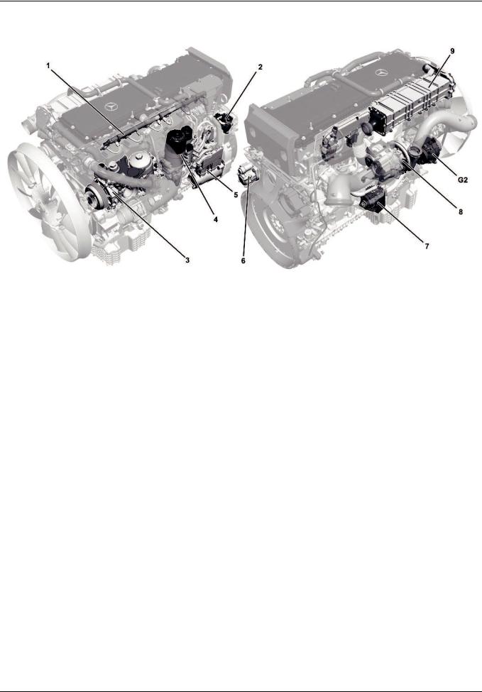
Engine
SN00.00>W>0002>04H |
Engine OM!471 |
|
|
|
|
|
|
|
|
|
|
|
|
|
|
|
|
|
|
|
W01.10>1090>09 |
1 |
Amplified Pressure Common>Rail |
4 |
Fuel filter module |
9 |
Cooled and regulated exhaust gas |
|
System (APCRS) |
5 |
Compressor |
|
recirculation (AGR) |
2 |
Diesel fuel>metering device (for |
6 |
Power steering pump |
|
|
|
regeneration of diesel particulate |
7 |
Oil separator for crankcase |
G2 |
Generator |
|
filter (DPF)) |
|
ventilation system |
|
|
3 |
Oil/coolant module |
8 |
Turbocharger |
|
|
The engine OM 471 is the first 6>cylinder inline engine with two overhead camshafts to be used in a Mercedes>Benz commercial vehicle.
Both camshafts are driven by a gear drive which is located at the output side of the engine. The position of this drive gear makes a major contribution to reducing noise emission.
The extremely compact design of the engine is based on the optimized cylinder liner concept in which the overhead seat is located at the bottom in the crankcase > this design measure
allows the gap between the cylinders to be reduced considerably.
>>>>>>>>>>>>>>>>>>>>>>>>>>>>>>>>>>>>>>>>>>>>>>>>>>>>>>>>>>>>>>>>>>>>>>>>>>>>>>>>>>>>>>>>>
The positive properties of the new engine have been made possible by a variety of new technical developments:
•The new injection system, the amplified pressure common rail system (APCRS) (1), is the first common rail system to be used in Mercedes>Benz commercial vehicles that minimizes the quantity of fuel required for combustion. The advantage of this system lies in the fact that the rail and high>pressure lines have a relatively low pressure of 900 bar, and the fuel pressure required for injecting into the injector is generated, which has a particularly positive effect on material loads and
therefore on component longevity.
>>>>>>>>>>>>>>>>>>>>>>>>>>>>>>>>>>>>>>>>>>>>>>>>>>>>>>>>>>>>>>>>>>>>>>>>>>>>>>>>>>>>>>>>>
i With each maintenance and repair work to the engine as well as to the ancillary assemblies and detachable parts comes the danger of property damage caused by soiling and foreign bodies. The high pressure diesel injection system, the intake system and the oil circuit, in particular, are at risk here.
The OM 471 engine is available in four output stages between 310 and 375 kW.
Advantages of new 6>cylinder inline engine:
•Lower fuel consumption in relation to high output
•Smooth running characteristics, whereby only four counterweights are required on the crankshaft
•Excellent application capability for the various emissions standards
•Implementation of particularly high combustion pressures of up to 230 bar
>>>>>>>>>>>>>>>>>>>>>>>>>>>>>>>>>>>>>>>>>>>>>>>>>>>>>>>>>>>>>>>>>>>>>>>>>>>>>>>>>>>>>>>>>
•The completely redesigned engine brake system has an even higher braking power.
•The cooled and regulated exhaust gas recirculation (EGR) (9) and the diesel particulate filter (DPF) as well as the modified oil separator of the crankcase ventilation system (7) ensure that tomorrow's emissions regulations can also be met.
•The regulated coolant pump installed in the oil/coolant module (3), which has already been installed in Actros
vehicles, also contributes to fuel economy.
>>>>>>>>>>>>>>>>>>>>>>>>>>>>>>>>>>>>>>>>>>>>>>>>>>>>>>>>>>>>>>>>>>>>>>>>>>>>>>>>>>>>>>>>>
To avoid any damage, when conducting repair work not only the specified special tools must be used along with observance of the WIS repair instructions, but in addition to this special care must be given to cleanliness at the workbay.
Additional information is available in the document AH00.00>N>5000>01H.
10
– This printout will not be recorded by the update service. Status: 09 / 2011 –

Technical data
SN00.00>W>0002>05H |
Technical data of diesel engine OM 471 |
|
|
|
|
|
|
|
|
|
|
|
|
|
|
|
|
General information |
|
|
|
|
|
|
|
|
|
|
OM 471 |
|
|
|
|
|
|
|
|
|
|
|
|
|
|
|
Displacement (l) |
|
12,8 |
|
|
|
|
|
|
|
|
|
|
|
|
|
|
|
No. of cylinders |
|
6 (in line) |
|
|
|
|
|
|
|
|
|
|
|
|
|
|
|
Valve control |
|
DOHC |
|
|
|
|
|
|
|
|
|
|
|
|
|
|
|
Valve number for each cylinder |
2/2 |
|
|
|
|
|
|
|
(intake/exhaust) |
|
|
|
|
|
|
|
|
|
|
|
|
|
|
|
|
|
Idle speed (rpm) |
|
560 |
|
|
|
|
|
|
|
|
|
|
|
|
|
|
|
Compression ratio (f) |
|
17,3 |
|
|
|
|
|
|
|
|
|
|
|
|
|
|
|
Stroke (mm) |
|
156 |
|
|
|
|
|
|
|
|
|
|
|
|
|
|
|
Stroke:bore ratio |
|
1,18 |
|
|
|
|
|
|
|
|
|
|
|
|
|
|
|
Weight (kg) |
|
approx. 1200 |
|
|
|
|
|
|
|
|
|
|
|
|
|
|
|
Power categories |
|
|
|
|
|
|
|
|
|
|
OM 471 with |
OM 471 with |
OM 471 with |
|
OM 471 with |
|
|
|
|
code M3A |
code M3B |
code M3C |
|
code M3D |
|
|
|
|
|
|
|
|
|
|
|
Output (kW) |
|
310 |
330 |
350 |
|
375 |
|
|
|
|
|
|
|
|
|
|
|
Output (horsepower) |
|
421 |
449 |
476 |
|
510 |
|
|
|
|
|
|
|
|
|
|
|
Torque (Nm) |
|
2100 |
2200 |
2300 |
|
2500 |
|
|
|
|
|
|
|
|
|
|
|
Piston |
|
|
|
|
|
|
|
|
|
|
OM 471 |
|
|
|
|
|
|
|
|
|
|
|
|
|
|
|
Diameter (mm) |
|
132 |
|
|
|
|
|
|
|
|
|
|
|
|
|
|
|
Overall height (mm) |
|
113 |
|
|
|
|
|
|
|
|
|
|
|
|
|
|
|
Compression height (mm) |
|
75 |
|
|
|
|
|
|
|
|
|
|
|
|
|
|
|
Shank length |
|
71,65 |
|
|
|
|
|
|
|
|
|
|
|
|
|
|
|
Piston pin |
|
|
|
|
|
|
|
|
|
|
OM 471 |
|
|
|
|
|
|
|
|
|
|
|
|
|
|
|
Inside diameter (mm) |
|
23.5 |
|
|
|
|
|
|
|
|
|
|
|
|
|
|
|
Outside diameter (mm) |
|
58 |
|
|
|
|
|
|
|
|
|
|
|
|
|
|
|
Length (mm) |
|
88 |
|
|
|
|
|
|
|
|
|
|
|
|
|
|
|
Fuel system |
|
|
|
|
|
|
|
|
|
|
OM 471 |
|
|
|
|
|
|
|
|
|
|
|
|
|
|
|
Rail pressure, max. (bar) |
|
900 |
|
|
|
|
|
|
|
|
|
|
|
|
|
|
|
Crankshaft bearing |
|
|
|
|
|
|
|
|
|
|
OM 471 |
|
|
|
|
|
|
|
|
|
|
|
|
|
|
|
Diameter (mm) |
|
114 |
|
|
|
|
|
|
|
|
|
|
|
|
|
|
|
Width (mm) |
|
36 |
|
|
|
|
|
|
|
|
|
|
|
|
|
|
|
Connecting rod |
|
|
|
|
|
|
|
|
|
|
OM 471 |
|
|
|
|
|
|
|
|
|
|
|
|
|
|
|
Length (mm) |
|
268 |
|
|
|
|
|
|
|
|
|
|
|
|
|
|
|
Connecting rod bearing |
|
|
|
|
|
|
|
|
|
|
OM 471 |
|
|
|
|
|
|
|
|
|
|
|
|
|
|
|
Diameter (mm) |
|
95 |
|
|
|
|
|
|
|
|
|
|
|
|
|
|
|
Width (mm) |
|
36,4 |
|
|
|
|
|
|
|
|
|
|
|
|
|
|
|
Crankcase, cylinder liner (wet) |
|
|
|
|
|
|
|
|
|
|
OM 471 |
|
|
|
|
|
|
|
|
|
|
|
|
|
|
|
Cylinder diameter (mm) |
|
132 |
|
|
|
|
|
|
|
|
|
|
|
|
|
|
|
Cylinder distance (mm) |
|
165 |
|
|
|
|
|
|
|
|
|
|
|
|
|||
|
|
|
|
|
||||
i Introduction of engine OM 471 and exhaust aftertreatment > 09/2011 > |
|
|
|
11 |
||||
– This printout will not be recorded by the update service. Status: 09 / 2011 –
As>built configurations
GF01.20>W>0801H |
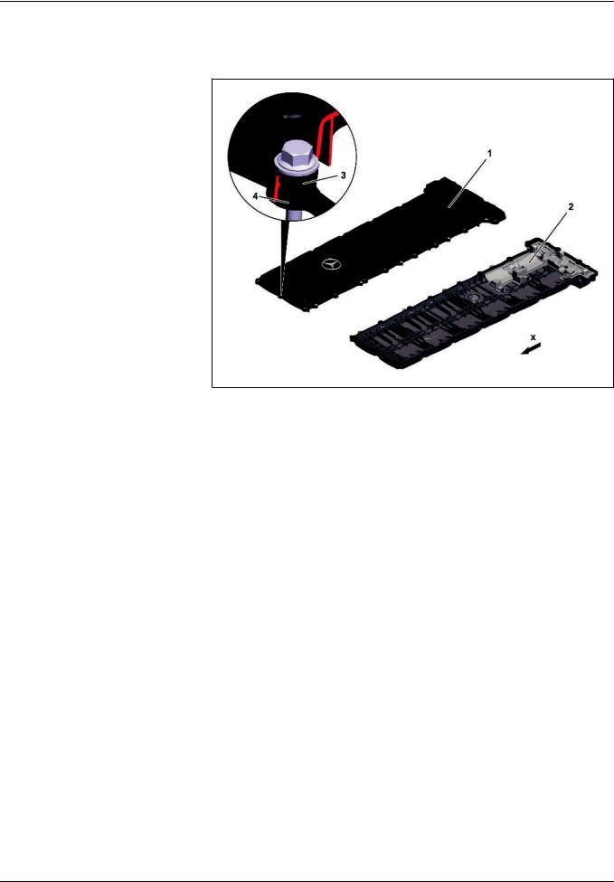
Cylinder head cover, as>built configuration |
1.7.11 |
|
|
|
ENGINES 471.9
1Cylinder head cover
2Prefilter
3 Elastomer element
4Elastomer seal
xDirection of travel
The cylinder head cover (1) consists of plastic and, on the one hand, prevents ingress of water and foreign objects into the valve assembly. On the other hand it seals the camshaft case to the outside using an elastomer seal (4) and prevents escape of the engine oil used to lubricate the valve assembly.
A prefilter (2) is integrated in the cylinder head cover (1). The prefilter (2) ensures that the engine oil which is swirled by the valve assembly and mixes with the blow>by gases is roughly separated before the blow>by gases are passed on to the oil separator for the crankcase ventilation system.
W01.20>1046>76
For acoustic decoupling of the cylinder head cover (1) an elastomer element (3) is inserted in all through holes which serve to attach the cylinder head cover (1) to the camshaft case. The elastomer elements (3) reduce noise emissions and possible damage which can occur due to vibrations.
12
– This printout will not be recorded by the update service. Status: 09 / 2011 –
As>built configurations
GF01.30>W>0800H |
Cylinder head, as>built configuration |
1.7.11 |
|
|
|
ENGINES 471.9
The engine OM 471 has a one>piece cylinder head.
There are two intake valves and two exhaust valves for each cylinder in the cylinder head. The narrow engine design means that overall a symmetrical location of the valves can ensue. This symmetrical valve pattern is optimum for the combustion.
Tightening procedure for cylinder head |
|
bolts |
|
1 > 38 Cylinder head bolt (M15¥2) |
39 Bolt (M10) |
Cylinder head bolts
In order to ensure that the correct bolts are used when installing the cylinder head, on each bolt head there is an embossing which provides information on the thread strength of the respective cylinder head bolt.
The cylinder head bolts have the M15 2 thread and therefore have the embossing "15".
All the cylinder head bolts must be tightened in four stages as per a set tightening pattern. The tightening torques and the tightening angle can be obtained from the repair instructions.
W01.30>1105>78
40 Bolt (M10)
As the cylinder head bolts elongate due to assembly, the shank length for each bolt which has already been used once must be measured before it is reassembled.
The relevant bolt must be replaced when the permissible shank length is exceeded.
i The cylinder head bolts are no longer assembled when the valve assembly is mounted. The valve assembly must be removed before dismantling the cylinder head.
i Introduction of engine OM 471 and exhaust aftertreatment > 09/2011 > |
13 |
– This printout will not be recorded by the update service. Status: 09 / 2011 –
As>built configurations
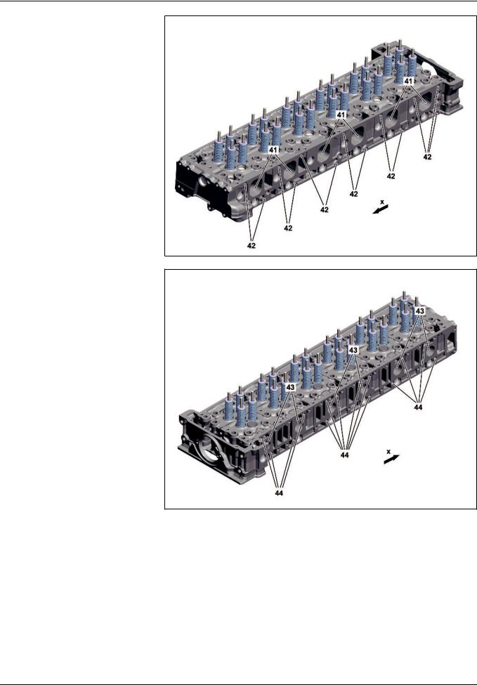
41Intake ports
42Threaded holes for the charge air manifold attachment
xDirection of travel
W01.30>1122>76
43Exhaust ducts
44Threaded holes for the charge air manifold attachment
xDirection of travel
W01.30>1123>76
14
– This printout will not be recorded by the update service. Status: 09 / 2011 –
As>built configurations
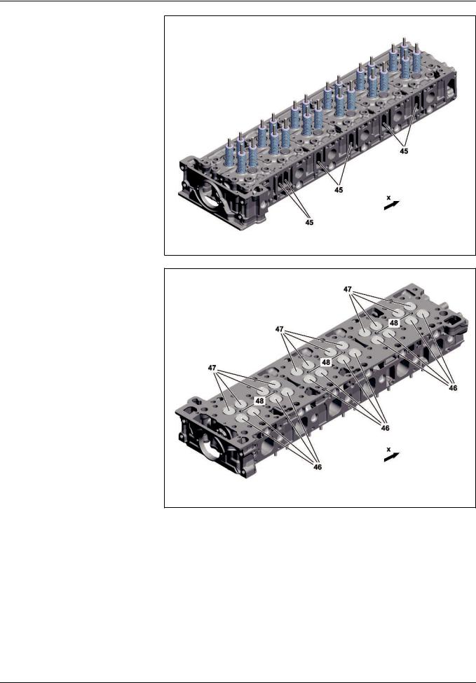
45 Connectors for coolant collector block
xDirection of travel
W01.30>1124>76
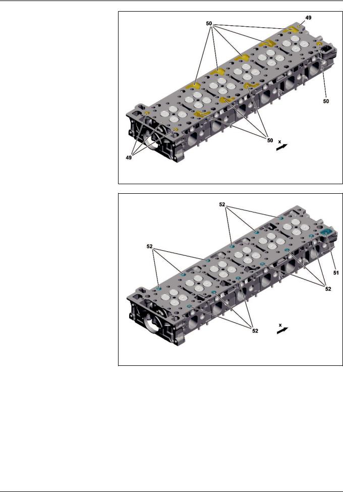
46Inlet valves
47Exhaust valves
48Bores for the fuel injectors
xDirection of travel
W01.30>1125>76
i Introduction of engine OM 471 and exhaust aftertreatment > 09/2011 > |
15 |
– This printout will not be recorded by the update service. Status: 09 / 2011 –
As>built configurations
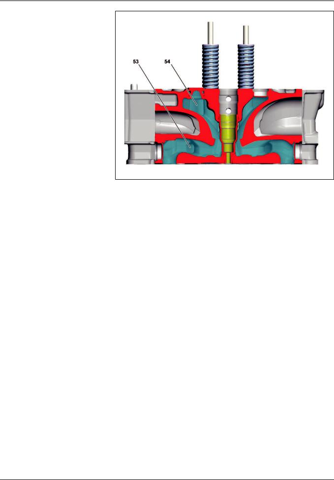
49OiI overflow holes from cylinder crankcase to cylinder head
50Oil return flow openings or oil return flow holes from cylinder head to cylinder crankcase
xDirection of travel
51Coolant short>circuit channel from cylinder head to cylinder crankcase
52Coolant overflow holes from cylinder crankcase to cylinder head
xDirection of travel
16
W01.30>1126>76
W01.30>1127>76
– This printout will not be recorded by the update service. Status: 09 / 2011 –
As>built configurations
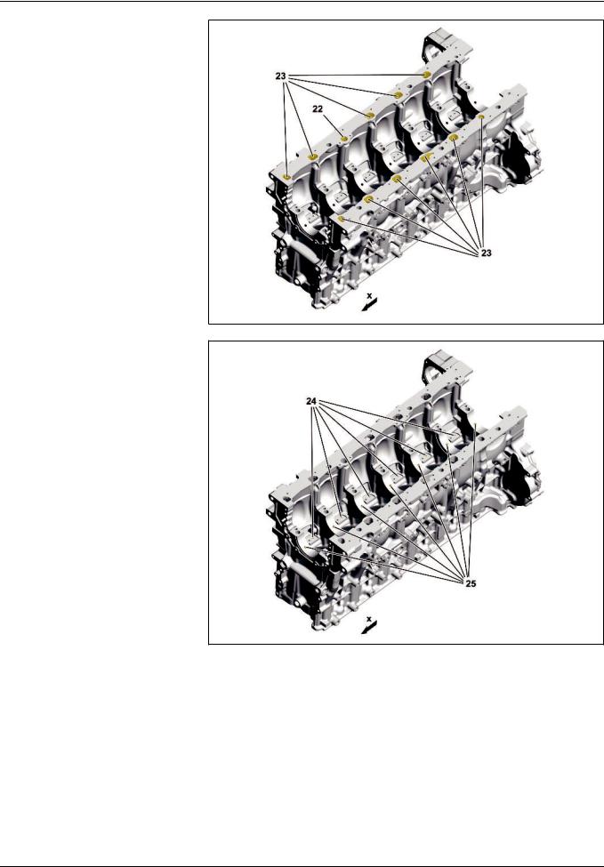
Cooling levers
53Lower cooling level
54Upper cooling level
Cooling
The cylinder head has a divided coolant jacket. This means that the coolant, after it has flushed around the cylinders, flows into the cylinder head on the inlet side and on the exhaust side. The advantage is that the coolant first flushes around the fuel injectors and valve seat rings in the lower cooling level (53) of the cylinder head.
W01.30>1128>76
After this the coolant flows into the upper cooling level (54) of the cylinder head and cools the valve guides. The coolant is collected there and directed outwards.
i Introduction of engine OM 471 and exhaust aftertreatment > 09/2011 > |
17 |
– This printout will not be recorded by the update service. Status: 09 / 2011 –
As>built configurations
GF01.30>W>0801H |
|
Cylinder head gasket, as>built configuration |
1.7.11 |
||
|
|
|
|
|
|
ENGINES 471.9 |
|
|
|
||
Upper side of the cylinder head seal |
|
|
|||
|
|
||||
OD |
Engine oil feed openings |
|
|
|
|
OR |
Engine oil return opening |
|
|
|
|
WR |
Coolant bypass duct opening |
|
|||
WZ |
Coolant feed opening |
|
|
|
|
KG |
Opening for the blow>by duct to the |
|
|||
|
crankcase ventilation system |
|
|||
xDirection of travel
W01.30>1120>06
The cylinder head gasket consists of a number of layers of stainless steel.
The cylinder head gasket at the engine oil feed openings (OD) and at the coolant feed opening (WZ) is fitted with raised elastomer elements through which the seal between the cylinder head and the cylinder crankcase is improved.
18
– This printout will not be recorded by the update service. Status: 09 / 2011 –

As>built configurations
GF01.40>W>0802H |
Crankcase as>built configuration |
1.7.11 |
|
|
|
ENGINES 471.9
Crankcase from above, shown with coolant ducts
1Coolant bypass duct
2 Recess for oil>water heat exchanger
3 Coolant connection for fuel cooler
4 Coolant connection for compressor
5Coolant connection for exhaust gas recirculation positioner
6Coolant overflow holes to the cylinder
head
7 Coolant return from the cylinder head
xDirection of travel
W01.40>1144>76
Crankcase from above, shown with oil ducts
8Oil hole closed longitudinally
9 Connection for the oil pressure sensor
10Oil return duct from oil filter (for changing the oil filter)
11Oil feed from oil/coolant module (from oil filter) to crankcase
12Oil feed from crankcase (from the oil pump) to
oil/coolant module
13Oil hole closed off laterally
14Bores for oil supply to the gear drive
|
|
|
|
|
W01.40>1145>76 |
15 |
Connection for oil supply of the |
17 |
Oil return duct from turbocharger |
20 |
OiI overflow holes to the cylinder |
|
centrifuge on the oil separator to the |
18 |
Connection for oil supply to the |
|
head |
|
crankcase ventilation system |
|
turbocharger |
21 |
Oil return ducts from cylinder head |
16 |
Oil return duct from oil separator for |
19 |
Oil hole closed off laterally |
|
|
|
crankcase ventilation system |
|
|
x |
Direction of travel |
i Introduction of engine OM 471 and exhaust aftertreatment > 09/2011 > |
19 |
– This printout will not be recorded by the update service. Status: 09 / 2011 –
As>built configurations
Crankcase from below, shown with oil ducts
22Oil return duct to oil/coolant module
23Oil return ducts to oil pan
xDirection of travel
Crankcase from below, shown with oil ducts
24Bores for oil supply to the oil spray nozzles
25Bores for oil supply to the main bearing, crankshaft and connecting rod bearing
xDirection of travel
W01.40>1146>76
W01.40>1147>76
The crankcase consists of cast iron and is characterized by the following features:
fa high rigidity and low noise emissions due to the vertical and horizontal reinforcements, as well as due to the design form of the oil return ducts
fa compact design due to the low distance from the cylinder
The crankcase also has 1.5 mm recesses at the sealing surface to the cylinder head for all coolant overflow holes to the cylinder head (6) and for all oil overflow holes to the cylinder head (20). These serve to receive the respective elastomer elements in the cylinder head gasket.
The following major assemblies and components are located on the crankcase:
Right>hand side
fTurbocharger
fStarter
fOil separator for crankcase ventilation system
Left>hand side
fOil/coolant module
fEngine management (MCM) control unit
fFuel filter module
fFuel high pressure pump
fCompressor, power steering pump
20
– This printout will not be recorded by the update service. Status: 09 / 2011 –
As>built configurations
GF03.10>W>0800H |
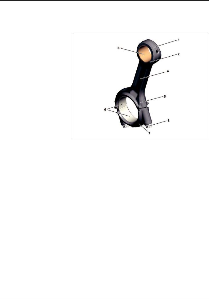
Connecting rod, as>built configuration |
1.7.11 |
|
|
|
ENGINES 471.9
1Connecting rod
2 Connecting rod small end (small)
3 Connecting rod bushing
4 Connecting>rod shank
5Connecting rod big end
6 Connecting rod bearing shells
7 Connecting rod bearing cap
8Stretch bolt
W03.10>1119>76
The connecting rods are forged in steel and are characterized by their high strength.
The connecting point between the connecting rod (1) and the connecting rod bearing cap (7) is cracked. This has the advantages, amongst other things, that one has no offset after screwing together both parts and the connecting rod bearing cap (7) cannot slip.
A connecting rod bushing (3) is pressed into a small connecting rod small end (2).
i Introduction of engine OM 471 and exhaust aftertreatment > 09/2011 > |
21 |
– This printout will not be recorded by the update service. Status: 09 / 2011 –
As>built configurations
GF03.10>W>0801H |
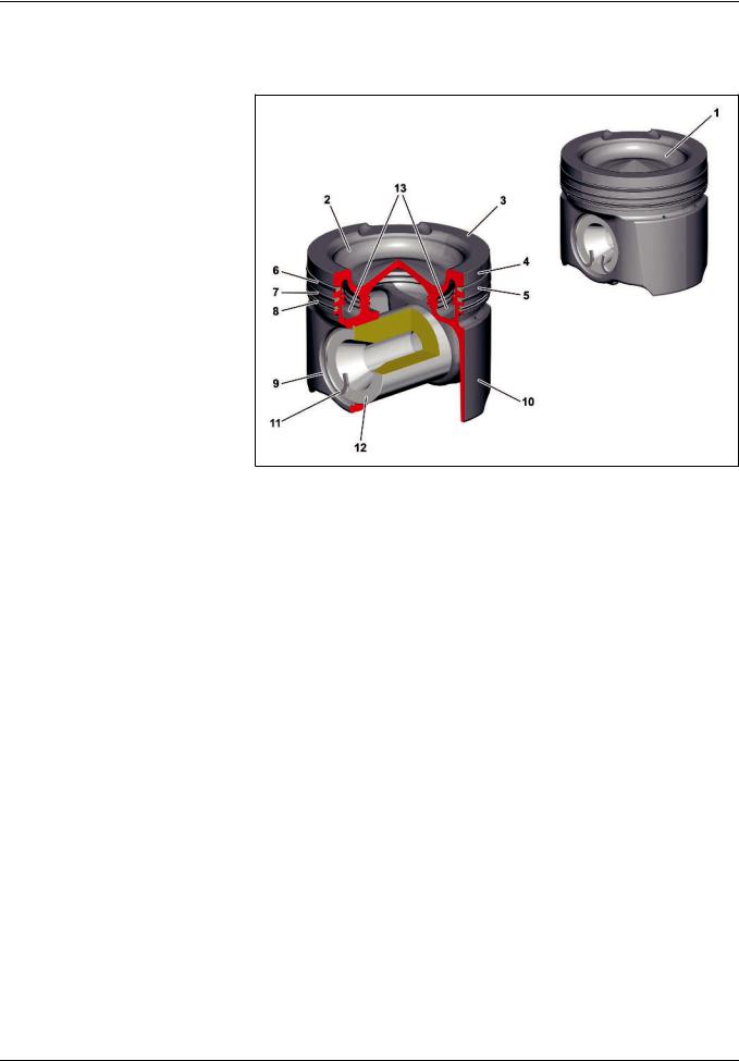
Piston, as>built configuration |
2.8.11 |
|
|
|
ENGINE 471.9
1Piston
2 Combustion recess
3 Piston crown
4Top land
5 Piston ring zone
6 1st piston ring
7 2nd piston ring
8 Oil scraper ring
9 Bolt eye
10Piston skirt
11Piston bolt circlip
12Piston pin
13Cooling duct
Feature
|
OM 471 |
|
|
Version |
Two piece |
|
|
Material |
Steel |
|
|
Weight (with spring steel sheet) |
3,339 KG |
|
|
Piston diameter |
132 mm |
|
|
Bolt diameter |
58 mm |
|
|
Surface |
friction optimized |
|
|
Piston (1)
The piston (1) consists of a forged upper section and a forged lower section, which are connected to each other by means of a friction weld.
Piston crown (3)
The piston crown (3) is fitted with a combustion recess (2). Through the combustion recess (2) the clearance volume is partially transferred into the piston (1).
Top land (4)
The top land (4) protects the 1st piston ring (6) against excessively
heating during the combustion process.
>>>>>>>>>>>>>>>>>>>>>>>>>>>>>>>>>>>>>>>>>>>>>>>>>>>>>>>>>>>>>>>>>>>>>>>>>>>>>>>>>>>>>>>>>
W03.10>1124>76
Piston ring zone (5)
The 1st piston ring (6), the 2nd piston ring (7) and the oil scraper ring (8) are located in the piston ring zone (5).
The 1st piston ring (6), the 2nd piston ring (7) take on the task of fine sealing to the crankcase.
The oil scraper ring (8) wipes off excess oil on the cylinder wall and leads the oil back into the oil pan.
Piston skirt (10)
The piston skirt (10) serves to guide the piston (1) into the cylinder liner. It transfers the lateral forces to the cylinder wall.
Located in the piston skirt (10) is the bolt eye (9) which supports
the piston pin (12).
>>>>>>>>>>>>>>>>>>>>>>>>>>>>>>>>>>>>>>>>>>>>>>>>>>>>>>>>>>>>>>>>>>>>>>>>>>>>>>>>>>>>>>>>>
22
– This printout will not be recorded by the update service. Status: 09 / 2011 –
As>built configurations
Cooling
The piston (1) is cooled via an oil spray nozzle for each cylinder located in the crankcase.
The oil spray nozzle continuously sprays engine oil into an injection opening in the cooling duct (13). Due to the coaxial spray direction of the oil spray nozzle the greatest possible throughput of engine oil is achieved in the cooling duct (13) and thus cooling of the piston is improved significantly.
One further opening which is located on the opposite side serves as a drain.
Additional bores in the cooling duct (13) serve to achieve better lubrication of the piston pin (12) and the connecting rod bearing bushing.
Protecting the contact surfaces
In order to protect the contact surfaces the friction, above all in the startup phase of the engine, is reduced by the applied protective coatings. This allows a longer working life and engine damage is avoided by the emergency running characteristics which result from the coating if the lubrication is faulty.
GF03.20>W>0800H |
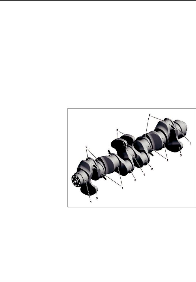
Crankshaft, as>built configuration |
2.8.11 |
|
|
|
ENGINE 471.9
1Crankshaft bearing journals
2 Connecting rod bearing journals
3Counterweight
Arrows Oil holes
The crankshaft is mounted in the crankcase with 7 crankshaft bearing journals (1).
Counterweights (3) are forged onto the webs to avoid vibrations arising.
The crankshaft bearing journals (1) and the connecting rod journals (2) are inductively hardened and ground in the surface layer.
W03.20>1216>06
There are oil holes (arrows) on the crankshaft bearing journals (1) and on the connecting rod journal (2) over which the crankshaft bearing and connecting rod bearing are lubricated.
i Introduction of engine OM 471 and exhaust aftertreatment > 09/2011 > |
23 |
– This printout will not be recorded by the update service. Status: 09 / 2011 –
As>built configurations
GF05.00>W>0800H |
Valve control; as>built configuration |
1.7.11 |
|
|
|
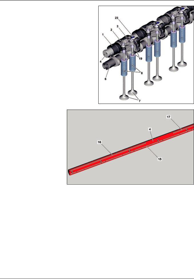
ENGINES 471.9
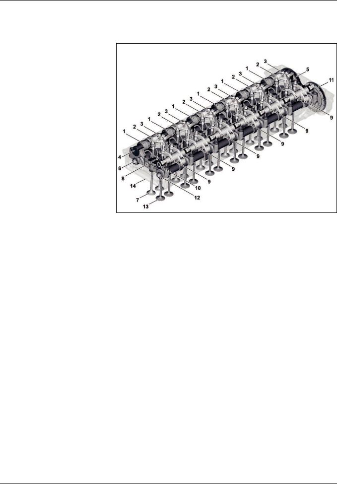
Valve control overall
1Exhaust rocker arm
2Exhaust rocker arm with
hydroelement
3Brake rocker arm
4Exhaust rocker arm spindle
5 Drive gear for exhaust camshaft
6 Exhaust camshaft
7 Outlet valve
8Valve spring
9Intake rocker arm
10Intake rocker arm spindle
11Drive gear for intake camshaft
12Intake camshaft
13Inlet valve
14Camshaft frame
W05.00>1033>06
The gas exchange system in the combustion chambers is controlled via the valve control.
Components of the valve control include:
•Two upper recumbent camshafts > the intake camshaft (12) and the exhaust camshaft (6), which are driven by the gear drive via the pinion gear drive for the intake camshaft (11) or via the pinion gear drive for the exhaust camshaft (5)
•Two rocker arm spindles > the intake rocker arm spindle (10) and the exhaust rocker arm spindle (4) on which the intake rocker arm (9) or exhaust rocker arm (1), the exhaust rocker arm with hydroelement (2) as well as the brake rocker arm
(3) are mounted
•Two exhaust valves (7) and two intake valves (13) per cylinder which are located symmetrically and pressed onto their seat via the valve springs (8) if they are not actuated by the corresponding rocker arm.
24
– This printout will not be recorded by the update service. Status: 09 / 2011 –
As>built configurations
Valve control on the exhaust side
1Exhaust rocker arm
2 Exhaust rocker arm with hydroelement
3Brake rocker arm
4 Exhaust rocker arm spindle
6 Exhaust camshaft
7 Exhaust valves
8Valve springs
19 Adjusting elements for adjusting the valve clearance
23 Adjusting element for engine brake
W05.00>1034>82
Design of the exhaust rocker arm spindle
(4)
4 Exhaust rocker arm spindle
15Lubricating oil duct
16Oil duct for cylinders 1 and 3
17Oil duct for cylinders 4 and 6
W05.00>1035>75
i Introduction of engine OM 471 and exhaust aftertreatment > 09/2011 > |
25 |
– This printout will not be recorded by the update service. Status: 09 / 2011 –
As>built configurations
|
W05.00>1036>01 |
|
W05.00>1037>01 |
|
W05.00>1038>01 |
Design of the rocker arm |
|
|
|
|
|
1 |
Exhaust rocker arm |
2 |
Exhaust rocker arm with |
3 |
Brake rocker arm |
18 |
Rocker arm roller |
|
hydroelement |
18 |
Rocker arm roller |
19 |
Adjusting element for adjusting the |
18 |
Rocker arm roller |
23 |
Adjusting element for engine brake |
|
valve clearance |
19 |
Adjusting element for adjusting the |
|
|
20 |
Oil inlet hole |
|
valve clearance |
|
|
|
|
20 |
Oil inlet hole |
|
|
|
|
21 |
Piston |
|
|
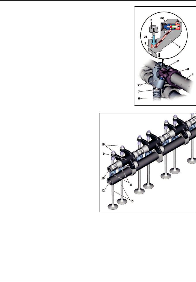
The valve control of the exhaust side is characterized by the fact that every cylinder has three rocker arms > one exhaust rocker arm (1), one exhaust rocker arm with hydroelement (2) and one brake rocker arm (3).
All rocker arms are fitted with a rocker arm roller (18). Use of rocker arm rollers (18) means that wear between the respective actuation cams of the exhaust camshaft (6) and the corresponding rocker arm is reduced. The noise emission of the valve assembly is also reduced.
The exhaust rocker arm (1) and exhaust rocker arm with hydroelement (2) are each equipped with an adjusting element for adjusting the valve clearance (19). The clearance between the brake rocker arm (3) and exhaust rocker arm with hydroelement
(2) is set using the adjusting element for the engine brake (23). The exhaust rocker arm (1), exhaust rocker arm with hydroelement (2) and brake rocker arm (3) are mounted rotatable on the exhaust rocker arm spindle (4).
The exhaust rocker arm spindle (4) is made out of solid material due to the higher loads in the engine brake system and is fitted with oil ducts > a lubricating oil duct (15) and two oil ducts for operation of the engine brake.
Exhaust valve control for a deactivated engine brake
2 Exhaust rocker arm with hydroelement
3Brake rocker arm
4 Exhaust rocker arm spindle
6 Exhaust camshaft
7 Outlet valve
21Piston
22Check valve
Rotational movement of the camshaft is converted into linear travel by the exhaust cam on the exhaust camshaft (6) and transferred to the associated exhaust rocker arm on the exhaust rocker arm spindle (4). The exhaust rocker arms steer the linear travel in turn onto the respective exhaust valves (7) which are opened and then closed again by the valve springs.
Because the pistons (21) are pressed by a spring to their lower limit stop when the engine brake is deactivated, no contact takes place between the brake rocker arms (3) and the exhaust rocker arms with hydroelement (2) and the brake rocker arms (3) run in idle. This serves to prevent any unnecessary piston (21) motion and therefore any unnecessary wear.
W05.00>1024>73
26
– This printout will not be recorded by the update service. Status: 09 / 2011 –
As>built configurations
Exhaust valve control for an activated engine brake
2 Exhaust rocker arm with hydroelement
3Brake rocker arm
4 Exhaust rocker arm spindle
6 Exhaust camshaft
7 Outlet valve
21Piston
22Check valve
When in engine brake operation up to six exhaust valves (7), one per cylinder are opened as follows, according to the engine brake stage, by the brake cam of the exhaust camshaft (6): The corresponding exhaust rocker arms with hydroelement (2) have oil pressure applied to them in engine brake operation via the oil inlet hole (20). If the corresponding brake rocker arm (3) now presses on the piston (21), the check valve (22) is closed by the increased oil pressure. Depressurization is prevented and the downward movement of the respective brake rocker arm (3) is transmitted by the piston (21) onto the associated exhaust rocker arm with hydroelement (2) which opens the respective exhaust valve (7).
W05.00>1025>73
Valve control on the inlet side
8Valve springs
9Intake rocker arm
10 Intake rocker arm spindle
12Intake camshaft
13Inlet valves
19 Adjusting elements for adjusting the valve clearance
W05.00>1039>82
i Introduction of engine OM 471 and exhaust aftertreatment > 09/2011 > |
27 |
– This printout will not be recorded by the update service. Status: 09 / 2011 –
 Loading...