


 Loading...
OM 501 LA – OM 502 LA engines
Operating Instructions
O rd e r no . 6462 9807 02 Pa rt n o . 5 41 58 4 09 81 EN Ed i ti o n A , 0 8/03

Thank you for choosing this
Mercedes-Benz engine.
Please get to know your new MercedesBenz en gine first. Make sure you read the Operating Instructions in particular before using the engine for the first time. In this way you can ensure successful and safe use. At the same time you will avoid endangering yourself and others when o perating the engine.
Items of special equipment are marked with an asterisk *. The equipment in your Mercedes-Benz drive train may vary, depending on the version. Mercedes-Benz is constantly updating its engines to the state of the art. You cannot, therefore, base any claims on the data, illustrations or descriptions in these Operating Instructions.
Fo r furth er information co ntact a Mercedes-Benz Service Centre.
The Operating Instructions and Maintenance Booklet belong with the engine. You should therefore always keep them with the engine and pass them on to the new owner if you sell it.
The technical documentation team at DaimlerChrysler AG wishes you every success.

Contents
Introduction |
|
The aim of these Operating |
|
Instructions . . . . . . . . . . . . . . . . . . . . . |
5 |
Symbols . . . . . . . . . . . . . . . . . . . . . . . . |
6 |
Protection of the environment . . . . . . |
7 |
Operating safety . . . . . . . . . . . . . . . . . |
8 |
Correct use . . . . . . . . . . . . . . . . . . . . |
9 |
1 At a glance |
|
OM 501 LA overview . . . . . . . . . . . . . 12 OM 502 LA overview . . . . . . . . . . . . . 16 Location of sensors . . . . . . . . . . . . . . 20
Engine plate . . . . . . . . . . . . . . . . . . . . 22
2Before commissioning
General remarks . . . . . . . . . . . . . . . . 26 Type designation . . . . . . . . . . . . . . 26 Engine data card . . . . . . . . . . . . . . . 26 Description of the engine . . . . . . . . 27 Flame-start system* . . . . . . . . . . . . 28 Engine exhaust brake / constantlyopen throttle valves* . . . . . . . . . . . 29 Telligent® engine system . . . . . . . . 31
Transport/installation . . . . . . . . . . . 35
3Safety
Safety precautions . . . . . . . . . . . . . . . 38 Personnel requirements . . . . . . . . . . 39
Commissioning parts and modifications . . . . . . . . . . . . . . . . . . . 40
Safety /emergency running
programs . . . . . . . . . . . . . . . . . . . . . . 41 Replacement parts. . . . . . . . . . . . . . . 42
4Operation
Commissioning. . . . . . . . . . . . . . . . . . 44 Preparation . . . . . . . . . . . . . . . . . . . 44 Initial commissioning . . . . . . . . . . . 46 Starting the engine . . . . . . . . . . . . . 49
Monitoring engine operation . . . . . . 51 Charge current . . . . . . . . . . . . . . . . 51 Telligent® engine system . . . . . . . . 52 Oil pressure . . . . . . . . . . . . . . . . . . 52 Flame-start system* . . . . . . . . . . . . 53
Stopping the engine . . . . . . . . . . . . . . 54
Winter operation . . . . . . . . . . . . . . . . 55
Cleaning/protective treatment . . . . 57 Cleaning the engine . . . . . . . . . . . . 57 Cleaning the cooling system. . . . . . 58 Protective treatment . . . . . . . . . . . . 60 Service products . . . . . . . . . . . . . . . . 61 Diesel fuels. . . . . . . . . . . . . . . . . . . 62
Engine oils . . . . . . . . . . . . . . . . . . . |
64 |
Coolant . . . . . . . . . . . . . . . . . . . . . . |
65 |
5 Maintenance |
|
Maintenance instructions . . . . . . . . . |
68 |
Overview of work plans . . . . . . . . . . . |
69 |
Main ten ance service. . . . . . . . . . . . |
69 |
Additional work. . . . . . . . . . . . . . . . |
69 |
Additional work during every |
|
3rd maintenance service . . . . . . . . |
69 |
Work plans . . . . . . . . . . . . . . . . . . . . . |
70 |
Engine: Checking for leaks and |
|
general condition . . . . . . . . . . . . . . |
70 |
Lines and hoses on the engine: |
|
Checking for leaks and general |
|
condition . . . . . . . . . . . . . . . . . . . . . |
70 |
Engine: Oil change and filter |
|
replacement . . . . . . . . . . . . . . . . . . |
71 |
Adjusting the valve clearance . . . . . |
74 |
Fuel connections. . . . . . . . . . . . . . . |
78 |
Fuel prefilter with heated water |
|
separator*: Replacing the filter |
|
element . . . . . . . . . . . . . . . . . . . . . . |
79 |
Replacing the fuel filter element . . . |
81 |
Intake pipe between air cleaner |
|
and engine: Checking for leaks and |
|
general condition . . . . . . . . . . . . . . |
83 |

Contents
Poly-V-belt: Checking the condition |
83 |
Engine brake*: Checking the |
|
condition and adjustment . . . . . . . . |
88 |
Engine cooling system: Checking |
|
and correcting the fluid level and |
|
the antifreeze/ corrosion inhibitor . 90 |
|
Cooling and heatin g system: |
|
Checking for leaks and general |
|
condition . . . . . . . . . . . . . . . . . . . . . |
91 |
Renewing coo lan t . . . . . . . . . . . . . . |
93 |
6Practical advice
Malfunctions, causes and solutions 96
Jump-starting . . . . . . . . . . . . . . . . . . 104
7Technical data
Engine data . . . . . . . . . . . . . . . . . . . . 106
Test values and adjustment values 109 Tightening torques. . . . . . . . . . . . . . 110
8Glossary and index
Technical terms . . . . . . . . . . . . . . . . 113 Index . . . . . . . . . . . . . . . . . . . . . . . . . 115

Introduction
The aim of these Operating Instructions 
The aim of these Operating Instructions
These Operating Instructions are intended to assist you in all situatio ns with your new engine. Each section has a print register to help you find the information you require quickly:
1At a glance
This section gives you an overview o f the layout of important components in the engine.
2Getting started
This contains the basic information you require for initial operation. If this is your first Mercedes-Benz engine, you should read this section first.
3Safety
This section contains important aspects with regard to safety in the use of the Mercedes-Benz OM 501 LA and
OM 502 LA engines.
4Controls in detail
Here you will find all the information you will need when you are operating the engine.
5Operation
This is where you will find more detailed in - formation abo ut maintenance work.
6Practical advice
Here you will find practical help for possible problems.
7Technical data
All the important technical data for the en - gine is listed here.
8Glossary and index
The glossary of technical terms explains the most important technical terms.
The index is intended to help you find information quickly.
The engine documentation comprises the following:
these Operating Instructions
the Maintenance Booklet
Specifications for Service Products
You may receive additio nal supplements depen ding on the equipment.
5

Introduction
 Symbols
You will find the following symbols used in these Operating Instructions:
*This asterisk indicates special equipment. Since not all models have the same standard equipment, the layout of your engine may differ from certain descriptions and illustrations.
Wa rning |
G |
A warning draws your attention to possible risks of accident and injury to yourself and others.
You should therefore always read and observe all warning notices.
Environmental note |
H |
An environmental note gives you tips on the protection of the environment.
!
This note draws your attention to possible hazards to your engine.
i
This tip contains advice or further information you may find useful.
This symbol mean s that yo u have to do so mething.
A number of these symbols one after the other indicates a sequence of action s.
page |
This symbol indicates the page |
|
on which you will find further in- |
|
formation on the subject . |
This continuation symbol indicates an interrupted sequence of actions that will be continued on the next page.
-> |
This symbol in the glossary of |
|
technical terms means that the |
|
term fo llowing the arrow is also |
|
explained. |
6

Protection of the environment
Environmental note |
H |
DaimlerChrysler's declared policy is one of integrated environmental protection. This policy starts at the root causes and encompasses in its management decisions all the consequences for the environment which could arise from production processes or the products themselves.
The objectives are for the natural resources which form the basis of our existenceon this planet to be used sparingly and in a manner which takes the requirements of both nature and humanity into account.
Operate the engine in an environmentally responsible manner, and you will help to protect the environment.
Introduction
Protection of the environment 
Fuel consumption and engine wear depend on the operating conditions.
Therefore you should:
not warm up the engine in idling mode
switch off the engine during operationassociated waiting times
check fuel consumption
carry out the specified maintenance work regularly
7

Introduction
 Operating safety
The operating safety of an engine firstly depends on its proper installation into the complete system (e.g. vehicle, machine, etc.). Secondly, as operator or service perso nnel, you also have a direct in fluence on the safe operation of the engine.
Some of the requiremen ts for operating the en gine safely can be achieved by adhering to the specified maintenance intervals and en suring that the required maintenance work is carried o ut correctly.
However, safe engine operation also depends on correct servicing, such as checking the engine oil level at regular intervals.
Risk of accident |
G |
Improper operation of the engine, e.g. exceeding the permitted maximum engine speed in overrun mode or operating the engine with too little oil, can cause engine damage. Engine damage can lead to an increase in the risk of accident.
Therefore, observe the notes on operating the engine in these Operating Instructions.
Risk of accident |
G |
Faulty maintenance work or failure to carry out maintenance work, e.g. not changing the oil filter or not observing the correct maintenance interval, can cause engine damage. Engine damage can lead to an increase in the risk of accident.
Therefore, observe the notes on engine maintenance in these Operating Instructions.
8
Risk of accident |
G |
Work incorrectly carried out on electronic components and its software could impair the functioning of these components. Since the electronic systems are networked, this might also affect systems that have not been modified.
Always have work on or modifications to electronic components carried out at a qualified specialist workshop which has the necessary specialist knowledge and tools to carry out the work required.
Mercedes-Benz recommends that you use a Mercedes-Benz Service Centre for this purpose.
Introduction
Operating safety 
Correct use
The engine is only designed for installation in accordance with the specifications determined in the contract.
The manufacturer of the end product is personally respo nsible for the complete system of the end product, and in particular for the correct installation and compat - ibility of this engine with the complete system.
The engine must not be modified. DaimlerChrysler accepts no respon sibility for damage caused as the result of modifications.
Correct use of the engine includes adhering to these Operating In structions, adhering to the maintenance intervals and performing maintenance wo rk correctly in accordance with these Operating Instructions.
9

10

At a glance
OM 501 LA overview
OM 502 LA overview
Location of sensors
Engine plate
1
11
At a glance
 OM 501 LA overview
1
12

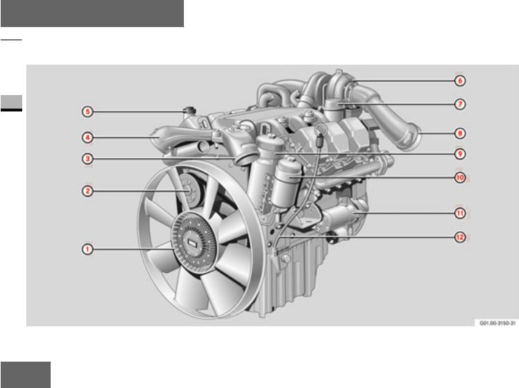
1 Fan
2 Coolant pump
3Charge-air pressure pipe (with flamestart system*) from charge-air cooler
4Charge-air pressure pipe to charge-air cooler
5 Oil filler neck
6 Exhaust gas turbocharger
7 Crankcase ventilation system oil trap
8 Exhaust pipe (with engine brake throttle valve*)
9 Oil filter a Fuel filter
b Starter motor c Dipstick
At a glance
OM 501 LA overview 
1 |
13
At a glance
 OM 501 LA overview
1
14

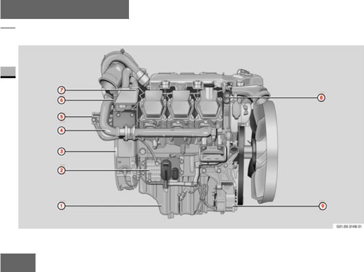
1 Oil sump
2 Engine control unit
3 Flywheel housing
4 Exhaust manifold
5Fuel pump (with flange-mounted power-steering pump*)
6 Air compressor*
7Resonator* (only in conjunctio n with air compressor)
8 Start-Stop buttons
9 Alternator
At a glance
OM 501 LA overview 
1 |
15
At a glance
 OM 502 LA overview
1
16

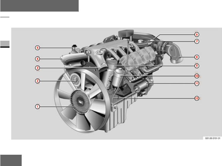
1 Fan
2 Coolant pump
3Charge-air pressure pipe (with flamestart system*) from charge-air cooler
4Charge-air pressure pipe to charge-air cooler
5 Oil filler neck
6 Exhaust gas turbocharger
7 Crankcase ventilation system oil trap
8 Exhaust pipe (with engine brake throttle valve*)
9 Oil filter a Fuel filter
b Starter motor c Dipstick
At a glance
OM 502 LA overview 
1 |
17

At a glance
 OM 502 LA overview
1
18
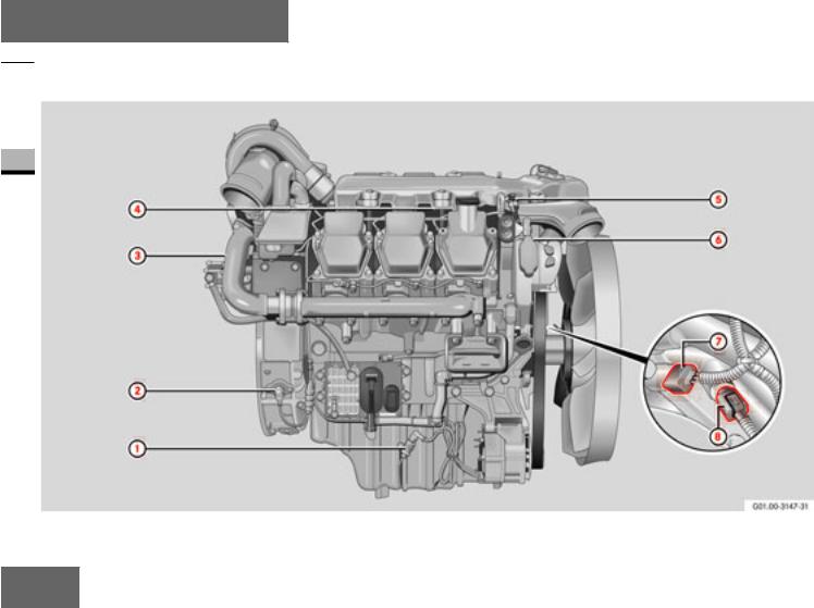
1 Oil sump
2 Engine control unit
3 Flywheel housing
4 Exhaust manifold
5Fuel pump (with flange-mounted power-steering pump*)
6 Air compressor*
7Resonator* (only in conjunctio n with air compressor)
8 Start-Stop buttons
9 Alternator
At a glance
OM 502 LA overview 
1 |
19
At a glance
 Location of sensors
1
20

1 Oil level sen sor
2Crankshaft position sensor (on the flywheel)
3Cylinder 1 TDC sensor (on the camshaft sprocket)
4 Fuel temperature sensor
5 Combined charge-air pressure and temperature sensor
6 Coolant temperature sensor
7 Oil pressure sensor
8 Oil temperature sensor
At a glance
Location of sensors 
1 |
21
At a glance
 Engine plate
|
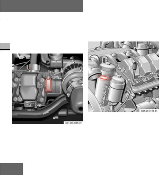
Location |
|
The engine plate is located on the left-hand |
1 |
side of the engine, on the engine block af- |
ter the last cylinder. |
A second engine plate is mounted on the front of the oil filter casing.
Engine plate, left -hand side of engine, fan end
Engine plate, left-hand side of engine, flywheel end
22
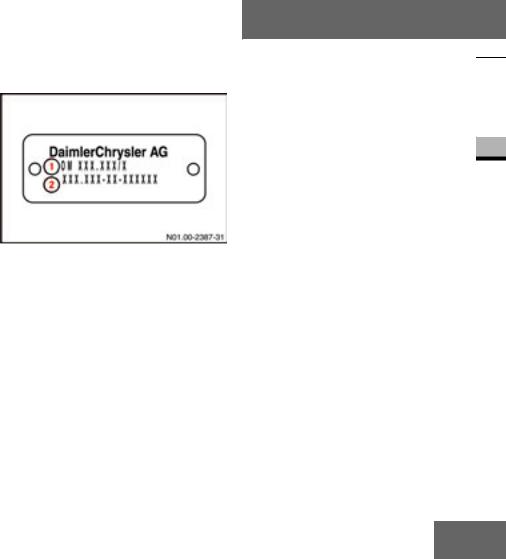
Information on the engine plate
On motor vehicles, the engine plate shows the engine model designation 1and the full engine number 2alon g with the manufacturer's name.
In addition to this, engines for mobile machines and equipment carry th e engine series designatio n and approval number.
Engine plate
1Engine mo del designation
2Engine number
At a glance
Engine plate 
1 |
23

24

Before commissioning
General remarks
Transport /installation
2
25

Before commissioning
 General remarks
Type designation
OM 501 L A
OM |
Oil engine (diesel |
2 |
en gine) |
501 |
Engine model1 |
LCharge-air co oling
AExhaust gas turbocharger
1 Engine model 501: 6-cylinder, engine model 502: 8-cylinder
|
Engine data card |
|
Engine data card |
||
|
The en gine data card (DIN A4 sheet) forms an integral part of the documents belonging to the engine and should always be kept with the Maintenan ce Booklet. It contains details about the engine's construction , in cluding special equipment features.
The engine data card must be produced for the procurement of genuine parts.
i
The engine data card describes the scope of delivery from the supplying factory; later changes to the scope of delivery are not included on the data card.
Always keep the engine data card with the Maintenance Bo oklet .
26

Description of the engine
The OM 501 LA and OM 502 LA engines are water-cooled 4-stroke direct injection diesel engines.
The 6 or 8 cylinders are arranged in a 90° V and have separate fuel-injection pumps (unit pumps) with a short highpressure fuel injection line to the multihole injection nozzle located centrally in relation to th e combustion chamber. Th e unit
pumps are mounted directly on the crankcase and is driven by the camshaft. Each cylinder has two inlet valves and two exhaust valves.
The OM 501 LA and OM 502 LA engines are equipped with an exhaust gas turbocharger and a charge-air cooler as standard. The engine can be optio nally equipped with an engine brake* (throttle valve and constantly-open throttle valves) and a flame-start system.
Thanks to their fully electronic control system for controlling the injection quantity and injection timing via solenoid valves, these are particularly low-emission engines.
The control system comprises an en gineresident control unit, an engine control (MR) with integrated heat exchanger for cooling by means of the forward fuel flo w and an application-related control unit, a vehicle con trol (FR) or an adaptation mo d- ule (ADM), all interconnected via the Controller Area Network (CAN).
Before commissioning
General remarks 
2 |
27
Before commissioning
 General remarks
2 |
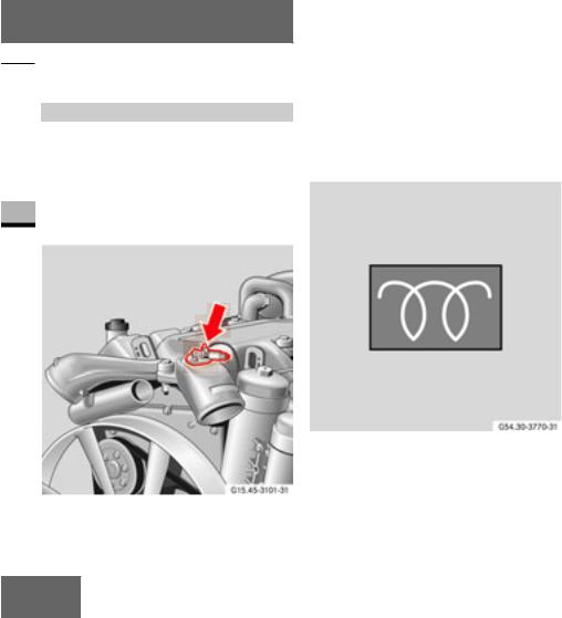
Flame-start system*
The flame-start system is a cold-start aid for starting at low outside temperatures. It reduces the white smoke emission after the en gine is started. In addition, it reduces the strain on the starter motor and batteries by shortening the startup time.
Fuel can be ignited by a flame heater plug mounted in the charge-air duct intake. The fuel is supplied to the flame heater plug via a solenoid valve with a dosin g jet.
The flame-start system is primed after a preglow time (maximum 20 seconds) which is dependent on the outside temperature. After this time the flame-start system indicator lamp goes out.
Once the engine has started, the flamestart system is supplied with fuel by the engine's fuel delivery pump.
Flame-start system indicator lamp (example)
Flame-start system
28
Loading...