


 Loading...
The Chamberlain Group, Inc. 845 Larch Avenue
Elmhurst, Illinois 60126-1196 www.liftmaster.com
®
COMMERCIAL DOOR OPENER
Model ATS 211X 1/2 HP
For Residential And Light Duty Commercial Use
Install on Sectional Doors Only
L O W H
IL
GA
H M
N O R
UP
FORCE
|
L |
|
O |
H |
W |
IL
GA
H M
N O R
DOWN
FORCE
Owner’s Manual
■Please read this manual and the enclosed safety materials carefully!
■Fasten the manual near the garage door after installation.
■The door WILL NOT CLOSE unless the Protector System® is connected and properly aligned.
■Periodic checks of the opener are required to ensure safe operation.
■The model number label is located on the front panel of your opener.

TABLE OF CONTENTS |
|
Introduction |
2-5 |
Safety symbol and signal word review........................ |
2 |
Preparing your garage door ........................................ |
3 |
Tools needed ............................................................... |
3 |
Planning ..................................................................... |
4 |
Carton inventory .......................................................... |
5 |
Hardware inventory ..................................................... |
5 |
Assembly |
6-7 |
Attach the rail to the motor unit ................................... |
6 |
Attach the chain to the sprocket and install |
|
the rail support bracket ............................................. |
6 |
Tighten the chain......................................................... |
7 |
Installation |
7-19 |
Installation safety instructions ..................................... |
7 |
Determine the header bracket location ....................... |
8 |
Install the header bracket............................................ |
9 |
Attach the rail to the header bracket ......................... |
10 |
Position the opener ................................................... |
11 |
Hang the opener........................................................ |
11 |
Install the door control............................................... |
12 |
Install the light ........................................................... |
13 |
Attach the emergency release rope and handle |
.......13 |
Electrical requirements.............................................. |
14 |
Install the Protector System®................................ |
15-17 |
Fasten the door bracket ............................................ |
18 |
Connect the door arm to the trolley .......................... |
19 |
Adjustment |
20-22 |
Adjust the travel limits ............................................... |
20 |
Adjust the force ......................................................... |
21 |
Test the safety reversal system................................. |
22 |
Test the Protector System®........................................ |
22 |
Operation |
23-25 |
Operation safety instructions..................................... |
23 |
Using your garage door opener ................................ |
23 |
Using the wall-mounted door control ........................ |
24 |
To open the door manually........................................ |
24 |
Care of your garage door opener.............................. |
24 |
Having a problem? .................................................... |
25 |
Programming |
26-28 |
3-Channel remote controls (Optional) ....................... |
26 |
Multi-Function door control (Optional)....................... |
27 |
To add or change a Keyless Entry PIN (Optional) ....28 |
|
Repair Parts |
29-30 |
Rail assembly parts ................................................... |
29 |
Installation parts ........................................................ |
29 |
Motor unit assembly parts ......................................... |
30 |
Accessories |
31 |
Repair Parts and Service |
32 |
Warranty |
32 |
INTRODUCTION
Safety Symbol
and Signal Word Review
This garage door opener has been designed and tested to offer safe service provided it is installed, operated, maintained and tested in strict accordance with the instructions and warnings contained in this manual.
 WARNING
Mechanical
 WARNING
Electrical
CAUTION
When you see these Safety Symbols and Signal Words on the following pages, they will alert you to the possibility of serious injury or death if you do not comply with the warnings that accompany them. The hazard may come from something mechanical or from electric shock. Read the warnings carefully.
When you see this Signal Word on the following pages, it will alert you to the possibility of damage to your garage door and/or the garage door opener if you do not comply with the cautionary statements that accompany it. Read them carefully.
2
Preparing your garage door
Before you begin:
•Disable locks.
•Remove any ropes connected to garage door.
•Complete the following test to make sure your garage door is balanced and is not sticking or binding:
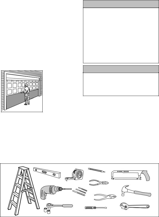
1.Lift the door about halfway as shown. Release the door. If balanced, it should stay in place, supported entirely by its springs.
2.Raise and lower the door to see if there is any binding or sticking.
If your door binds, sticks, or is out of balance, call a trained door systems technician.
Sectional Door
 WARNING
To prevent possible SERIOUS INJURY OR DEATH:
•ALWAYS call a trained door systems technician if garage door binds, sticks, or is out of balance. An unbalanced garage door may not reverse when required.
•NEVER try to loosen, move or adjust garage door, door springs, cables, pulleys, brackets or their hardware, all of which are under EXTREME tension.
•Disable ALL locks and remove ALL ropes connected to garage door BEFORE installing and operating garage door opener to avoid entanglement.
•This product is for use on sectional garage doors only. SERIOUS INJURY could result from the use of this product on one piece garage doors.
CAUTION
To prevent damage to garage door and opener:
•ALWAYS disable locks BEFORE installing and operating the opener.
•ONLY operate garage door opener at 120V, 60 Hz to avoid malfunction and damage.
Tools needed
During assembly, installation and adjustment of the opener, instructions will call for hand tools as illustrated below.
Carpenter’s
Level (Optional)
Pencil
1 |
2 |
Hack Saw
Tape Measure
Wire Cutters
|
Drill |
3/16", 5/16" and |
|
Claw Hammer |
|
|
5/32" Drill Bits |
|
Pliers |
|
|
|
|
|
Stepladder |
1/2" and 7/16" Sockets |
Screwdriver |
|
|
and Wrench |
|
Adjustable End Wrench |
||
|
|
|
||
3

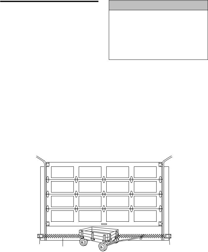
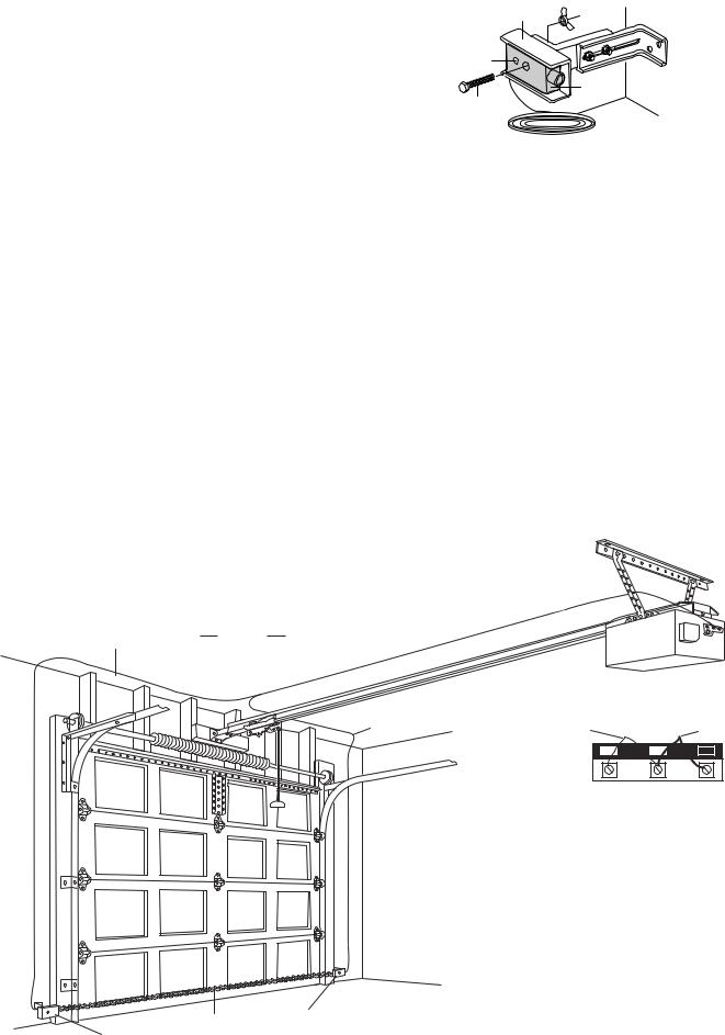
Planning
Identify the type and height of your garage door. Survey your garage area to see if any of the conditions below apply to your installation. Additional materials may be required. You may find it helpful to refer back to this page and the accompanying illustrations as you proceed with the installation of your opener.
 WARNING
Without a properly working safety reversal system, persons (particularly small children) could be SERIOUSLY INJURED or KILLED by a closing garage door.
•The gap between the bottom of the garage door and the floor MUST NOT exceed 1/4". Otherwise, the safety reversal system may not work properly.
•The floor or the garage door MUST be repaired to eliminate the gap.
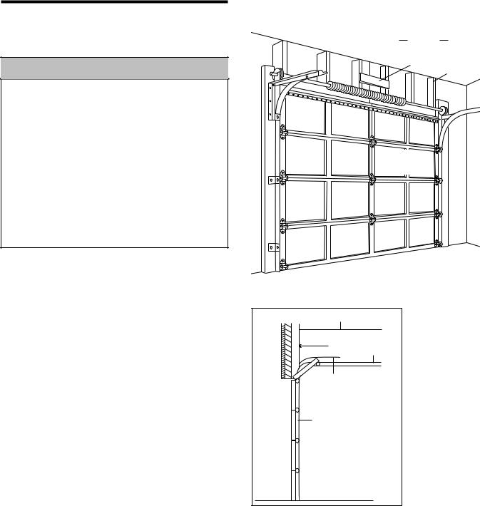
SECTIONAL DOOR INSTALLATION
Horizontal and vertical reinforcement is needed for lightweight garage doors
(fiberglass, steel, aluminum, door with glass panels, etc.). See page 18 for details.
Slack in chain tension is normal when garage door is closed.
FINISHED CEILING
Support bracket & fastening hardware is required.
See page 11.
Header Wall
—— Door Center —
— — —
— —
Gap between floor and bottom of door must not exceed 1/4"
Safety Reversing Sensor
Extension Spring |
|
|
OR |
|
|
Torsion Spring |
Wall- |
|
mounted |
||
Access Door |
||
Door |
||
|
||
|
Control |
Safety |
|
|
|
|
|
Reversing |
|
|
|
|
|
Sensor |
|
|
|
|
|
|
Header |
Chain Pulley |
|
CLOSED POSITION |
|
|
Bracket |
Bracket |
|
|
Rail |
|
|
Chain |
Trolley |
||
|
|
|
|||
|
|
|
|
|
|
|
|
Garage |
|
|
|
|
|
Door |
|
|
|
|
|
Spring |
|
|
Emergency |
|
|
|
|
|
|
|
|
|
|
|
Release |
|
|
Straight |
|
Rope & Handle |
|
|
|
Door |
|
|
|
|
|
Arm |
|
|
|
|
|
Curved |
|
|
|
|
|
Door |
|
|
|
Header |
|
Arm |
|
|
|
Wall |
Door Bracket |
|
|
|
|
Garage |
|
|
|
||
|
|
|
|
|
|
Door |
|
|
|
|
|
4 |
|
|
|
|
|
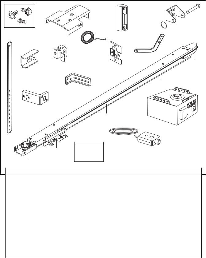
Carton Inventory
Your garage door opener is packaged in two cartons which contain the motor unit and all parts illustrated below. Accessories will depend on the model
purchased. If anything is missing, carefully check the packing material. Parts may be stuck in the foam. Hardware for installation is also listed below.
|
LY |
NT |
ON |
|
|
OU |
|
G M |
|
ILIN |
|
CE |
|
UP |
|
Header Bracket with
Clevis Pin and Fastener
Mounting Hardware |
Rail Support |
|
|
(Rail Support Bracket) |
Lighted Door |
||
Bracket |
|||
|
Control Button |
||
|
|
||
|
|
2 -Conductor Bell Wire |
|
|
|
White & White/Red |
Curved Door Arm
Styrofoam
Door Bracket
Door Bracket Plate
"C" Wrap (2)
Chain
Safety Reversing Sensor
Mounting Bracket
With Slot (2)
Safety Reversing Sensor
Mounting Bracket
With Square Holes (2)
Rail
Motor Unit
Straight
Door Arm
Trolley |
Safety Labels |
|
and Literature |
Chain
Pulley Bracket
(2) Safety Reversing Sensors
(1 Sending Eye and 1 Receiving Eye) with 2-Conductor White & White/Black Bell Wire attached
HARDWARE INVENTORY
Assembly Hardware |
Installation Hardware |
Hardware for Safety |
|
Washered Screw, 5/16"-18x1/2" |
Hex Screw 5/16"-18x7/8" (4) |
Reversing Sensor |
|
|
|||
(2) (Mounted in Opener) |
Nut 5/16"-18 (4) |
Lag Screw 1/4x1-1/2" (4) |
|
Hex Screw 1/4"-20x5/8" (2) |
Lock Washer 5/16" (4) |
Carriage Bolt 1/4"-20x1/2" (4) |
|
Lock Nut 1/4"-20 (4) |
|||
Lock Washer 1/4"-20x5/8" (2) |
Rail Grease |
||
Wing Nut (2) |
|||
Screw #8-32x3/8" (1) |
Lag Screw 5/16"-9x1-5/8" (4) |
||
Washered Screw |
Screw 6ABx1-1/2" (2) |
Hex Screw 1/4-20x1-1/2" (2) |
|
5/16"-18x1/2" (2) |
Handle |
Screw #10-32x3/8" (4) |
|
|
Ring Fastener (3) |
Lock Nut #10x32 (4) |
|
|
Self-Threading Screw |
Insulated Staples (20) |
|
|
1/4"-14x5/8" (2) |
|
|
|
Insulated Staples (10) |
|
|
|
Drywall Anchors (2) |
|
|
|
Clevis Pin 5/16"x2-3/4" (1) |
|
|
|
Clevis Pin 5/16"x1" (2) |
|
|
|
Rope |
|
5
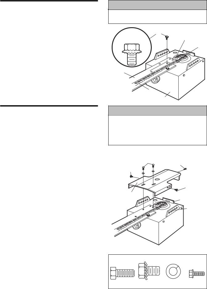
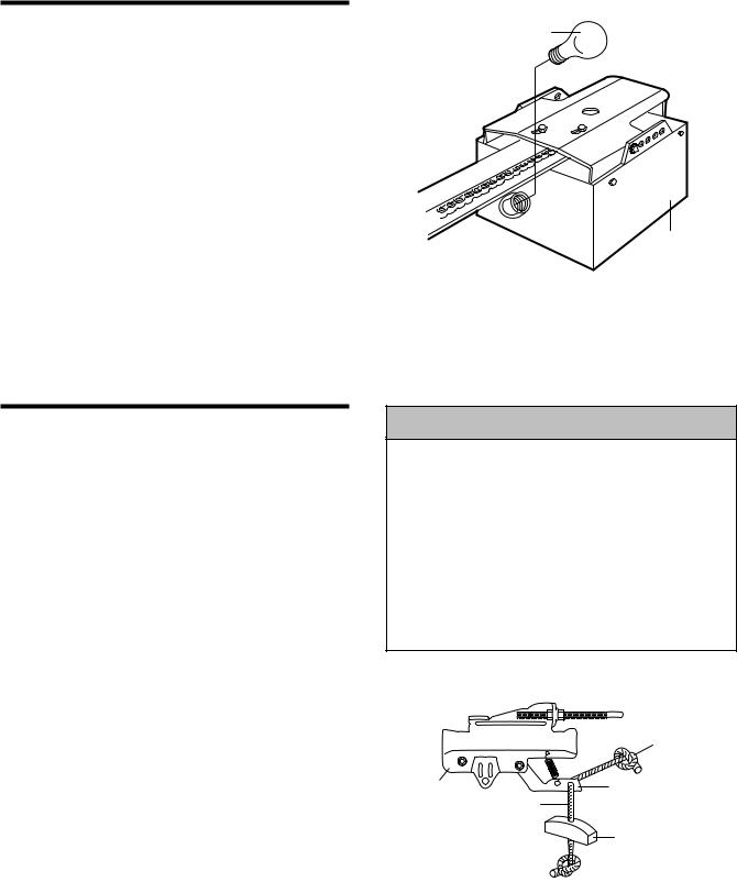
ASSEMBLY STEP 1
Attach the Rail to the Motor Unit
To avoid installation difficulties, do not run the garage door opener until instructed to do so.
•Place the opener on packing material to protect the cover.
•Remove the (2) 5/16"-18x1/2" washered bolts mounted in the top of the motor unit.
•Position rail at a 45˚ angle to opener so one hole in rail and motor unit line up.
•Thread one of the washered bolts part way in.
Use only these bolts! Use of any other bolts will cause serious damage to door opener.
• Align rail over sprocket. Cut tape from rail.
ASSEMBLY STEP 2
Attach the Chain to the Sprocket and Install the Rail Support Bracket
•Guide the chain over chain spreader and opener sprocket. If necessary, loosen the outer nut on the trolley to obtain more chain slack. Insert the second washered bolt. Use only the bolts previously removed from opener.
•Tighten both bolts securely through the rail into the opener as shown.
•Position the rail support bracket on the opener.
•Attach the bracket to the rail with 1/4"-20x5/8" hex screws and lock washers. Do not overtighten.
•Attach the bracket to the opener by inserting a 5/16"-18x1/2" washered bolt through a hole in each side flange and a matching hole in the bracket. Complete the connection by inserting the #8-32x3/8" screw through the back flange and the hole in rail support.
Proceed to Assembly Step 3.
CAUTION
To avoid SERIOUS damage to opener, ONLY use bolts/fasteners mounted in top of motor unit.
|
Washered Bolt |
|
5/16"-18x1/2" |
USE ONLY THIS |
Chain |
TYPE AND SIZE |
Spreader |
BOLT |
|
Sprocket
Rail
Chain
Opener
 WARNING
To avoid possible SERIOUS INJURY to fingers from moving garage door opener:
•ALWAYS keep hand clear of sprocket while operating opener.
•Securely attach rail support bracket BEFORE operating.
Hex bolts
with Lock Washers
1/4"-20x5/8" Screw #8-32x3/8"
Washered Bolt 5/16"-18x1/2"
Washered Bolt 5/16"-18x1/2"
Rail Support |
Opener |
|
Bracket |
||
Back Flange |
||
|
Opener
Side Flange
HARDWARE SHOWN ACTUAL SIZE
Hex Bolt |
Washered Bolt |
Lock Washer |
Screw |
1/4"-20x5/8" |
5/16"-18x1/2" |
|
#8-32x3/8" |
6
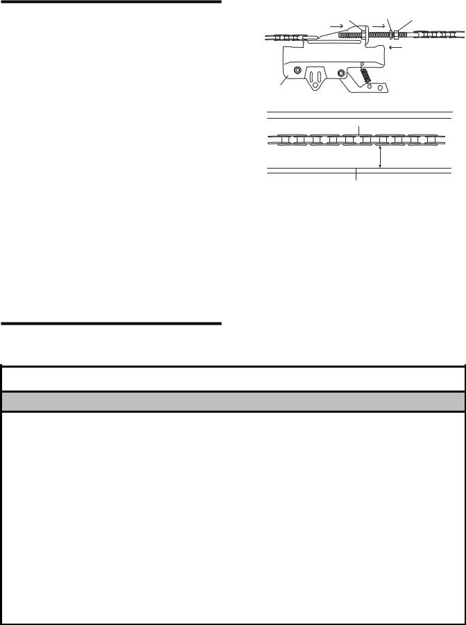
ASSEMBLY STEP 3
Tighten the Chain
•Spin the inner nut and lock washer down the threaded shaft, away from the trolley.
•To tighten the chain, turn outer nut in the direction shown. As you turn the nut, keep the chain from twisting.
•When the chain is approximately 1/2" above the base of the rail at its midpoint, re-tighten the inner nut to secure the adjustment.
Sprocket noise can result if chain is either too loose or too tight.
When installation is complete, you may notice some chain droop with the door closed. This is normal. If the chain returns to the position shown when the door is open, do not re-adjust the chain.
NOTE: During future maintenance, ALWAYS pull the emergency release handle to disconnect trolley before adjusting chain.
You have now finished assembling your garage door opener. Please read the following warnings before proceeding to the installation section.
INSTALLATION
|
Lock |
|
Outer Nut |
Washer |
Inner Nut |
To Tighten Outer Nut |
|
|
|
|
|
|
|
To Tighten |
|
|
Inner Nut |
Trolley |
|
|
Chain |
|
|
1/2 Inch
Base of rail
IMPORTANT INSTALLATION INSTRUCTIONS
 WARNING
To reduce the risk of severe injury or death:
1.READ AND FOLLOW ALL INSTALLATION WARNINGS AND INSTRUCTIONS.
2.Install garage door opener only on properly balanced and lubricated garage door. An improperly balanced door may not reverse when required and could result in SEVERE INJURY or DEATH.
3.All repairs to cables, spring assemblies and other hardware MUST be made by a trained door systems technician BEFORE installing opener.
4.Disable all locks and remove all ropes connected to garage door BEFORE installing opener to avoid entanglement.
5.Install garage door opener 7 feet or more above floor.
6.Mount emergency release handle 6 feet above floor.
7.NEVER connect garage door opener to power source until instructed to do so.
8.NEVER wear watches, rings or loose clothing while installing or servicing opener. They could be caught in garage door or opener mechanisms.
9.Install wall-mounted garage door control:
•within sight of the garage door
•out of reach of children at minimum height of 5 feet
•away from all moving parts of the door.
10.Place entrapment warning label on wall next to garage door control.
11.Place manual release/safety reverse test label in plain view on inside of garage door.
12.Upon completion of installation, test safety reversal system. Door MUST reverse on contact with a 1-1/2" high object (or a 2x4 laid flat) on the floor.
7
INSTALLATION STEP 1
Determine the Header Bracket
Location
 WARNING
To prevent possible SERIOUS INJURY or DEATH:
•Header bracket MUST be RIGIDLY fastened to structural support on header wall or ceiling, otherwise garage door might not reverse when required. DO NOT install header bracket over drywall.
•Concrete anchors MUST be used if mounting header bracket or 2x4 into masonry.
•NEVER try to loosen, move or adjust garage door, springs, cables, pulleys, brackets, or their hardware, all of which are under EXTREME tension.
•ALWAYS call a trained door systems technician if garage door binds, sticks, or is out of balance. An unbalanced garage door might not reverse when required.
1.Close the door and mark the inside vertical centerline of the garage door.
2.Extend the line onto the header wall above the door.
You can fasten the header bracket within 4 feet of the left or right of the door center only if a torsion spring or center bearing plate is in the way; or you can attach it to the ceiling (see page 9) when clearance is minimal. (It may be mounted on the wall upside down if necessary, to gain approximately 1/2".)
If you need to install the header bracket on a 2x4 (on wall or ceiling), use lag screws (not provided) to securely fasten the 2x4 to structural supports as shown here and on page 9.
3.Open your door to the highest point of travel as shown. Draw an intersecting horizontal line on the header wall 2" above the high point. This height will provide travel clearance for the top edge of the door.
Proceed to Step 2, page 9.
Finished
Ceiling
Header |
2x4 |
Structural |
Wall |
||
|
|
Supports |
 Vertical
Centerline
of Garage Door
Ceiling
Header Wall

 2" Track
Highest Point
of Travel
Sectional door
with curved
track
Door
8
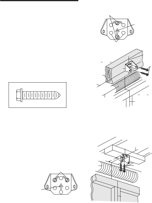
INSTALLATION STEP 2
Install the Header Bracket
You can attach the header bracket either to the wall above the garage door, or to the ceiling. Follow the instructions which will work best for your particular requirements. Do not install the header bracket over drywall. If installing into masonry, use concrete anchors (not provided).
WALL HEADER BRACKET INSTALLATION
•Center the bracket on the vertical centerline with the bottom edge of the bracket on the horizontal line as shown (with the arrow pointing toward the ceiling).
•Mark the vertical set of bracket holes (do not use the holes designated for ceiling mount). Drill 3/16" pilot holes and fasten the bracket securely to a structural support with the hardware provided.
HARDWARE SHOWN ACTUAL SIZE
Lag Screw 5/16"-9x1-5/8"
Wall Mounting Holes
CEILING MOUNT ONLY
UP
Optional
Wall Mounting Holes
|
Header |
|
Wall |
2x4 |
Header |
Structural |
Bracket |
Support |
|
Horizontal |
|
Line |
|
Highest Point of
Garage Door Travel 
|
LY |
NT |
ON |
OU |
|
G M |
|
ILIN |
|
CE |
|
UP |
|
The nail hole is for positioning only.
You must use lag screws
to mount the header bracket.
Vertical
Centerline
of Garage Door
Lag Screws 5/16"-9x1-5/8"
Door Spring
Garage
Door
Vertical
Centerline
of Garage Door
CEILING HEADER BRACKET INSTALLATION
•Extend the vertical centerline onto the ceiling as shown.
•Center the bracket on the vertical mark, no more than 6" from the wall. Make sure the arrow is pointing toward the wall. The bracket can be mounted flush against the ceiling when clearance is minimal.
•Mark the side holes. Drill 3/16" pilot holes and fasten bracket securely to a structural support with the hardware provided.
Ceiling Mounting Holes
CEILING MOUNT ONLY
UP
The nail hole is for positioning only.
You must use lag screws
to mount the header bracket.
— Finished Ceiling —
|
Vertical |
|
Header |
Centerline |
|
Bracket |
of Garage Door |
|
PU |
|
|
6" Maximum |
|
|
Door |
Lag Screws |
|
Spring |
||
5/16"-9x1-5/8" |
||
|
||
|
Header Wall |
|
Garage Door |
|
Vertical
Centerline
of Garage Door
9
Header Wall
Header
Bracket
Chain
Pulley
Bracket
Rail
Garage
Door
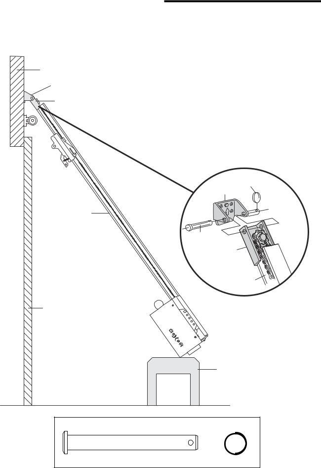
INSTALLATION STEP 3
Attach the Rail to the Header Bracket
•Position the opener on the garage floor below the header bracket. Use packing material as a protective base. NOTE: If the door spring is in the way you’ll need help. Have someone hold the opener securely on a temporary support to allow the rail to clear the spring.
•Position the chain pulley bracket against the header bracket.
•Align the bracket holes and join with a clevis pin as shown.
•Insert a ring fastener to secure.
Ring Fastener
Header Bracket
Clevis Pin 5/16"x2-3/4"
Chain
Pulley
Bracket
Rail
Temporary
Support
HARDWARE SHOWN ACTUAL SIZE
Clevis Pin |
|
5/16"x2-3/4" |
Ring Fastener |
10
INSTALLATION STEP 4
Position the Opener
SECTIONAL DOOR ONLY
A 2x4 laid flat is convenient for setting an ideal door-to-rail distance.
•Remove foam packaging.
•Raise the opener onto a stepladder. You will need help at this point if the ladder is not tall enough.
•Open the door all the way and place a 2x4 laid flat on the top section beneath the rail.
Trolley
Release Arm
ENGAGED |
RELEASED |
CAUTION
To prevent damage to garage door, rest garage door opener rail on 2x4 placed on top section of door.
•If the top section or panel hits the trolley when you raise the door, pull down on the trolley release arm to disconnect inner and outer sections. Slide the outer trolley toward the motor unit. The trolley can remain disconnected until Installation Step 12
is completed.
Rail |
2 x 4 |
|
Door
INSTALLATION STEP 5
Hang the Opener
Two representative installations are shown. Yours may be different. Hanging brackets should be angled (Figure 1) to provide rigid support. On finished ceilings (Figure 2), attach a sturdy metal bracket to structural supports before installing the opener. This bracket and fastening hardware are not provided.
1.Measure the distance from each side of the motor unit to the structural support.
2.Cut both pieces of the hanging bracket to required lengths.
3.Drill 3/16" pilot holes in the structural supports.
4.Attach one end of each bracket to a support with 5/16"-18x1-7/8" lag screws.
5.Fasten the opener to the hanging brackets with 5/16"-18x7/8" hex bolts, lock washers and nuts.
6.Check to make sure the rail is centered over the door (or in line with the header bracket if the bracket is not centered above the door).
7.Remove the 2x4. Operate the door manually. If the door hits the rail, raise the header bracket.
8.Grease the top and underside of the rail surface where the trolley slides with rail grease.
HARDWARE SHOWN ACTUAL SIZE
Lag Screw 5/16"-9x1-5/8"
Hex Bolt |
|
|
5/16"-18x7/8" |
Nut 5/16"-18 |
Lock Washer 5/16" |
 WARNING
To avoid possible SERIOUS INJURY from a falling garage door opener, fasten it SECURELY to structural supports of the garage. Concrete anchors MUST be used if installing any brackets into masonry.
Structural
Supports
Figure 1
Lag Screws 5/16"-9x1-5/8"
Measure
Distance
Bolt 5/16"-18x7/8"
Lock Washer 5/16"
Nut 5/16"-18
Hidden Support |
FINISHED CEILING |
|
Lag Screws |
|
5/16"-9x1-5/8" |
Bracket |
(Not Provided) |
Bolt 5/16"-18x7/8" |
|
(Not Provided) |
Lock Washer 5/16" |
|
Nut 5/16"-18 |
Figure 2
Bolt 5/16"-18x7/8"
Lock Washer 5/16"
Nut 5/16"-18
11
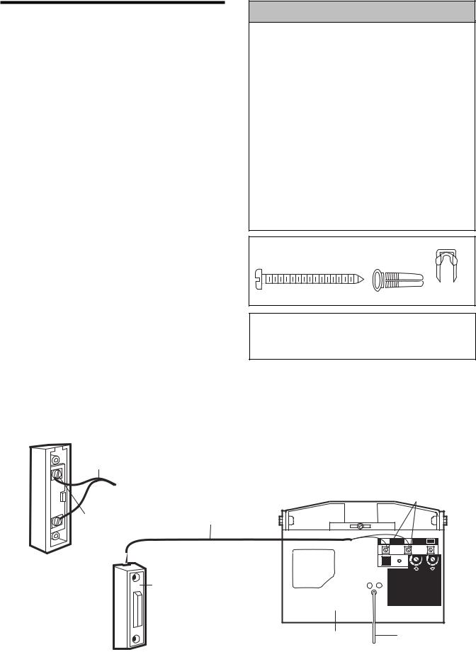
INSTALLATION STEP 6
Install the Door Control
Locate the door control within sight of the door at a minimum height of 5 feet where small children cannot reach, and away from all moving parts of the door and door hardware.
1.Strip 1/4" of insulation from one end of the bell wire. Connect it to the two screw terminals on the back of the door control by color: white wire to 2 and white/red wire to 1.
2.Fasten the Lighted Door Control Button securely with 6ABx1-1/2" screws. If installing into drywall, drill 5/32" holes and use the anchors provided.
3.Run the bell wire up the wall and across the ceiling to the opener. Use insulated staples to secure the wire in several places. Be careful not to pierce the wire with a staple, creating a short or open circuit.
4.Receiver terminal screws and the antenna are located on the back panel of the motor unit. Position the antenna wire as shown.
5.Connect the bell wire by color to the opener terminal screws: white to 2 and white/red to 1.
6.Use tacks or staples to permanently attach the entrapment warning label to the wall near the door control, and the manual release/safety reverse test in a prominent location on the inside of the
garage door.
NOTE: DO NOT connect the power and operate the opener at this time. The trolley will travel to the full open position, but will not return to the close position until the sensor beam is connected and properly aligned. See Safety Reversing Sensor instructions beginning on page 15.
2-Conductor Bell Wire
WHT |
|
|
-2 |
|
|
RED |
Lighted |
2-Conductor |
-1 |
||
|
Door Control |
Bell Wire |
|
Terminal Screws |
|
Lighted
Door Control
Button

 WARNING
To prevent possible SERIOUS INJURY or DEATH from electrocution:
•Be sure power is not connected BEFORE installing door control.
•Connect ONLY to 24 VOLT low voltage wires.
To prevent possible SERIOUS INJURY or DEATH from a closing garage door:
•Install door control within sight of garage door, out of reach of children at a minimum height of 5 feet, and away from all moving parts of door.
•NEVER permit children to operate or play with door control push buttons or remote control transmitters.
•Activate door ONLY when it can be seen clearly, is properly adjusted, and there are no obstructions to door travel.
•ALWAYS keep garage door in sight until completely closed. NEVER permit anyone to cross path of closing garage door.
HARDWARE SHOWN ACTUAL SIZE
Screw 6ABx1-1/2" |
Drywall Anchors |
Insulated |
Lighted Door Control Button |
Staples |
Outside Keylock Accessory Connections
To opener terminal screws: White to 2 and white/red to 1.
Opener
Terminal
Screws
1 |
2 |
|
|
3 |
|
9 |
1 |
9 |
1 |
|
7 |
3 |
7 |
3 |
|
|
5 |
|
5 |
|
|
KG |
|
KG |
Back Panel |
Antenna |
|
|
|
|
|
|
|
|
of Opener |
|
|
|
|
12
INSTALLATION STEP 7
Install the Light
•Install a 75 watt maximum light bulb in the socket. The light will turn ON and remain lit for approximately 4-1/2 minutes when power is connected. Then the light will turn OFF.
•If the bulb burns out prematurely due to vibration, replace with a "Garage Door Opener" bulb.
NOTE: Use only standard light bulbs. The use of short neck or speciality light bulbs may overheat the endpanel or light socket.
75 Watt Max.
Light Bulb
Opener
INSTALLATION STEP 8
Attach the Emergency Release
Rope and Handle
•Thread one end of the rope through the hole in the top of the red handle so "NOTICE" reads right side up as shown. Secure with an overhand knot at least 1" from the end of the rope to prevent slipping.
•Thread the other end of the rope through the hole in the release arm of the outer trolley.
•Adjust rope length so the handle is 6 feet above the floor. Secure with an overhand knot.
NOTE: If it is necessary to cut the rope, heat seal the cut end with a match or lighter to prevent unraveling.
 WARNING
To prevent possible SERIOUS INJURY or DEATH from a falling garage door:
•If possible, use emergency release handle to disengage trolley ONLY when garage door is CLOSED. Weak or broken springs or unbalanced door could result in an open door falling rapidly and/or unexpectedly.
•NEVER use emergency release handle unless garage doorway is clear of persons and obstructions.
NEVER use handle to pull door open or closed. If rope knot becomes untied, you could fall.
Trolley
Rope
NOTICE
Overhand
Knot
Trolley
Release Arm
Emergency
Release Handle
13
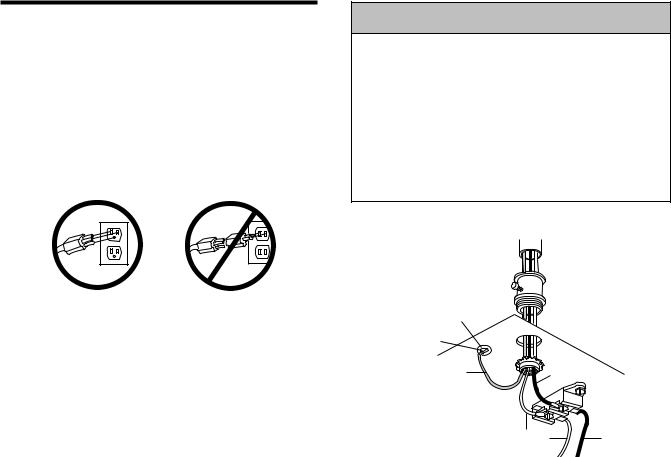
INSTALLATION STEP 9
Electrical Requirements
To avoid installation difficulties, do not run the opener at this time.
To reduce the risk of electric shock, your garage door opener has a grounding type plug with a third grounding pin. This plug will only fit into a grounding type outlet. If the plug doesn't fit into the outlet you have, contact a qualified electrician to install the proper outlet.
RIGHT |
WRONG |
If permanent wiring is required by your local code, refer to the following procedure.
To make a permanent connection through the 7/8" hole in the top of the motor unit:
•Remove the motor unit cover screws and set the cover aside.
•Remove the attached 3-prong cord.
•Connect the black (line) wire to the screw on the brass terminal; the white (neutral) wire to the screw on the silver terminal; and the ground wire to the green ground screw. The opener must be grounded.
•Reinstall the cover.
To avoid installation difficulties, do not run the opener at this time.
 WARNING
To prevent possible SERIOUS INJURY or DEATH from electrocution or fire:
•Be sure power is not connected to the opener, and disconnect power to circuit BEFORE removing cover to establish permanent wiring connection.
•Garage door installation and wiring MUST be in compliance with all local electrical and building codes.
•NEVER use an extension cord, 2-wire adapter, or change plug in ANY way to make it fit outlet. Be sure the opener is grounded.
PERMANENT WIRING
CONNECTION
Ground Tab
Green
Ground Screw
Ground Wire |
Black |
Wire |
White Wire |
Black Wire |
14
INSTALLATION STEP 10
Install The Protector System®
The safety reversing sensor must be connected and aligned correctly before the garage door opener will move in the down direction.
IMPORTANT INFORMATION ABOUT
THE SAFETY REVERSING SENSOR
When properly connected and aligned, the sensor will detect an obstacle in the path of its electronic beam. The sending eye transmits an invisible light beam to the receiving eye. If an obstruction breaks the light beam while the door is closing, the door will stop and reverse to full open position, and the opener lights will flash 10 times.
The units must be installed inside the garage so that the sending and receiving eyes face each other across the door, no more than 6" above the floor. Either can be installed on the left or right of the door as long as the sun never shines directly into the receiving eye lens.
 WARNING
•Be sure power is not connected to the garage door opener BEFORE installing the safety reversing sensor.
•To prevent SERIOUS INJURY or DEATH from a closing garage door:
–Correctly connect and align the safety reversing sensor. This required safety device MUST NOT be disabled.
–Install the safety reversing sensor so beam is NO HIGHER than 6" above garage floor.
If it is necessary to mount the units on the wall, the brackets must be securely fastened to a solid surface such as the wall framing. If installing in masonry construction, add a piece of wood at each location to avoid drilling extra holes in masonry if repositioning is necessary.
The invisible light beam path must be unobstructed. No part of the garage door (or door tracks, springs, hinges, rollers or other hardware) may interrupt the beam while the door is closing.
Sensor Beam |
Invisible Light Beam |
Sensor Beam |
|
6" max. |
6" max. |
||
Protection Area |
|||
above floor |
above floor |
||
|
Facing the door from inside the garage
15
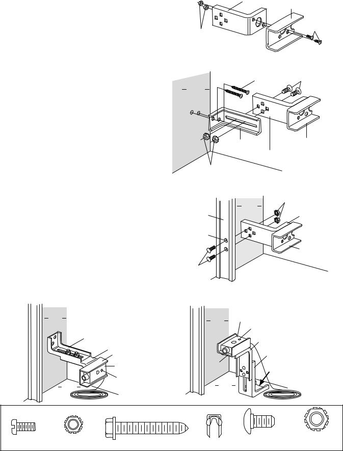
INSTALLING THE BRACKETS
Figure 1, 2 and 3 show recommended assembly of bracket(s) and “C” wrap based on the wall installation of the sensors on each side of the garage door as shown on page 15, or on the garage door tracks themselves.
Figure 4 and 5 are variations which may fit your installation requirements better. Make sure the wraps and brackets are aligned so the sensors will face each other across the garage door.
Garage Wall or Door Track Installation
1.Fasten the “C” wraps to the mounting brackets having square holes, using th hardware shown in Figure 1.
Garage Wall Installation
2.Connect each assembly to a slotted bracket, using the hardware show on Figure 2. Note alignment of brackets for left and right sides of door.
3.Finger tighten the lock nuts.
4.Use bracket mounting holes as a template to locate and drill (2) 3/16" diameter pilot holes on both sides of the garage door, 4"-6" above the floor but not exceeding 6" (see warning on page 15).
5.Attach bracket assembly with 1/4"x1-1/2" lag screws as shown in Figure 2.
6.Adjust right and left bracket assemblies to the same distance out from mounting surface. Make sure all door hardware obstructions are cleared. Tighten the nuts securely.
Garage Door Track Installation
Discard slotted bracket. Drill 3/8" holes in each track and fasten securely with hardware as shown in Figure 3.
Figure 4 |
Alternate Wall Mount |
Inside
Garage
Wall
Mounting Bracket with Slot
Mounting Bracket with Square Holes
"C" Wrap
Sensor with wire
Indicator Light
Garage
Floor
Figure 1
Garage WALL or DOOR Track Installation
Mounting Bracket
With Square Holes
"C" Wrap
Screws
#10-32x3/8"
Lock Nuts #10-32
Figure 2
Garage WALL Installation
Lag Screws |
Carriage Bolts1/4-20x1/2" |
1/4x1-1/2" |
(with square shoulder) |
Inside
Garage
Wall
Mounting Bracket |
"C" Wrap |
with Slot
Mounting Bracket with Square Holes
Lock Nuts 1/4"-20
Figure 3 |
|
Garage DOOR Track Installation |
|
|
|
Inside |
Lock Nuts 1/4" |
Garage |
|
Mounting Bracket |
|
|
Garage |
||
Door Track |
|
Wall |
with Square Holes |
Drill 3/8" |
|
|
|
Holes |
|
|
|
|
|
|
"C" Shaped |
|
|
|
Wrap |
Carriage Bolts |
|
|
|
1/4-20x1/2" |
|
|
|
Figure 5 |
Alternate Floor Mount |
||
|
Inside |
Sensor with wire |
|
|
Garage |
|
|
|
|
|
|
|
Wall |
Indicator Light |
|
|
|
||
|
|
Mounting Bracket |
|
|
|
with Square Holes |
|
|
|
|
Mounting Bracket |
|
|
|
with Slot |
"C" Wrap |
|
Attach with |
|
|
|
|
concrete anchors |
|
|
|
(not provided) |
|
Garage |
|
|
|
Floor |
|
|
|
|
HARDWARE SHOWN ACTUAL SIZE |
|
|
Screw |
Lock Nut |
Lag Screw 1/4x1-1/2" |
Carriage Bolts |
Lock Nut |
#10-32x3/8" |
#10x32 |
Staples |
1/4"-20x1/2" |
1/4"-20 |
16
MOUNTING AND WIRING THE SAFETY SENSORS
•Center each sensor unit in a "C" wrap with lenses pointing toward each other across the door
(see Figure 6).
•Secure sensors with the hardware shown. Finger tighten the wing nut on the receiving eye to allow for final adjustment. Securely tighten the sending eye wing nut.
•Run the wires from both sensors to the opener (see Figure 7). Use insulated staples to secure the wire to wall and ceiling.
•Strip 1/4" of insulation from each set of wires. Separate white and white/black wires sufficiently to connect to the opener terminal screws: white to 2 and white/black to 3.
ALIGNING THE SAFETY SENSORS
•Plug in the opener. The indicator lights in both the sending and receiving eyes will glow steadily if wiring connections and alignment are correct.
The sending eye indicator light will glow regardless of alignment or obstruction. If the indicator light in the receiving eye is off, dim, or flickering (and the invisible light beam path is not obstructed), alignment is required.
•Loosen the sending eye wing nut and readjust, aiming directly at the receiving eye. Lock in place.
•Loosen the receiving eye wing nut and adjust sensor until it receives the sender’s beam. When the green indicator light glows steadily, tighten the wing nut.
Figure 6 |
"C" Wrap |
Wing |
|
|
Nut |
Indicator
Light
Sensor with Wire
Hex Bolt 1/4-20 x 1-1/2"
TROUBLESHOOTING THE SAFETY SENSORS
1.If the sending eye indicator light does not glow steadily after installation, check for:
•Electric power to the opener.
•A short in the white or white/black wires. These can occur at staples, or at opener connections.
•Incorrect wiring between sensors and opener.
•A broken wire.
2.If the sending eye indicator light glows steadily but the receiving eye indicator light doesn't:
•Check alignment.
•Check for an open wire to the receiving eye.
3.If the receiving eye indicator light is dim, realign either sensor.
NOTE: When the invisible beam path is obstructed or misaligned while the door is closing, the door will reverse. If the door is already open, it will not close. The opener lights will blink 10 times. See page 15.
Figure 7
Connect Wire to
Opener Terminals
|
Finished |
Bell Wire |
Ceiling |
Bell Wire |
Wall Control |
|
Sensor |
|
Connections |
||
|
Connections |
|
|
|
(dotted line) |
|
|
|
1 |
2 |
3 |
OPENER TERMINAL SCREWS
|
Sensor |
|
Invisible Light Beam |
Sensor |
Protection Area |
17
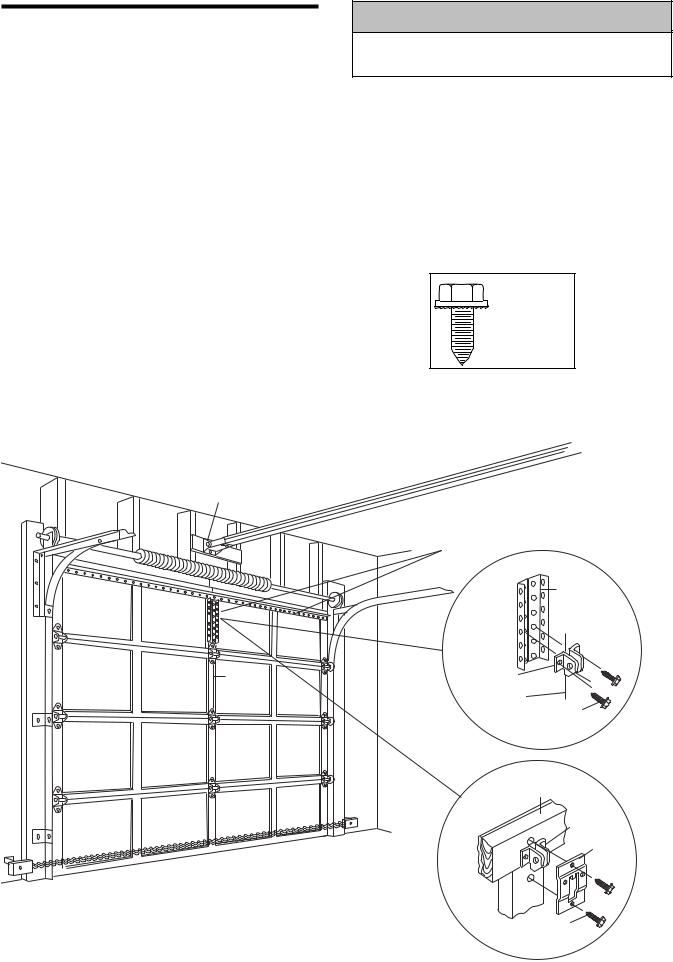
INSTALLATION STEP 11
Fasten the Door Bracket
A horizontal brace should be long enough to be secured to 2 vertical supports. A vertical brace should cover the height of the top panel.
The illustration shows one piece of angle iron as the horizontal brace. For the vertical brace, 2 pieces of angle iron are used to create a "U"-shaped support. The best solution is to check with your garage door manufacturer for an opener installation door reinforcement kit.
•Center the door bracket on the previously marked vertical guideline used for the header bracket installation.
•Position the bracket on the face of the door within the following limits:
A)The top edge of the bracket 2"-4" below the top edge of the door.
B)The top edge of the bracket directly below any structural support across the top of the door.
•Mark and drill 3/16" left and right fastening holes. Secure the bracket as shown in Figure 1 if there is vertical reinforcement.
Header
Bracket
Door
Bracket 
Location
Vertical
Guideline
CAUTION
To prevent damage to garage door, reinforce inside of door with angle iron both vertically and horizontally.
If your installation doesn't require vertical reinforcement but does need top and bottom fastening holes for the door bracket, fasten as shown in Figure 2.
HARDWARE
SHOWN
ACTUAL SIZE
Self-Threading Screw 1/4"-14x5/8"
Horizontal and vertical reinforcement is needed for lightweight garage doors (fiberglass, aluminum, steel,
doors with glass panel, etc).
Vertical
Reinforcement
Door
Bracket
Vertical
Guideline
Self-Threading Screw 1/4"-14x5/8"
Figure 2
Inside Edge of Door or
Reinforcement Board
Door
Bracket
Door
Bracket
Plate
Self-Threading Screw 1/4"-14x5/8"
18
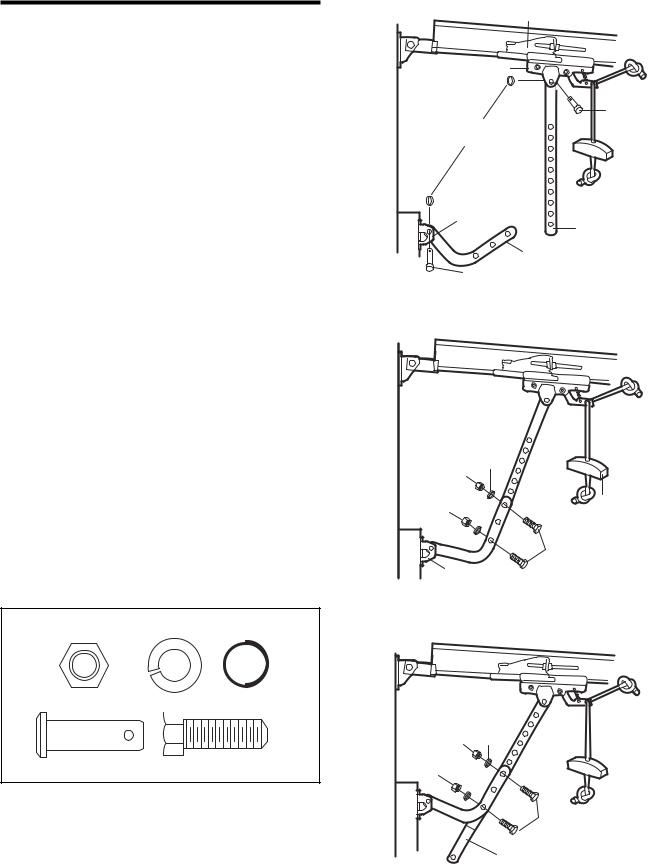
INSTALLATION STEP 12
Connect Door Arm to Trolley
SECTIONAL DOORS ONLY
•Make sure garage door is fully closed. Pull the emergency release handle to disconnect the outer trolley from the inner trolley. Slide the outer trolley back (away from the door) about 2" as shown in Figures 1, 2 and 3.
•Figure 1:
–Fasten straight door arm section to outer trolley with the 5/16"x1" clevis pin. Secure the connection with a ring fastener.
–Fasten curved section to the door bracket in the same way, using the 5/16"x1-1/4" clevis pin.
•Figure 2:
–Bring arm sections together. Find two pairs of holes that line up and join sections. Select holes as far apart as possible to increase door arm rigidity.
•Figure 3, Hole alignment alternative:
–If holes in curved arm are above holes in straight arm, disconnect straight arm. Cut about 6" from the solid end. Reconnect to trolley with cut end down as shown.
–Bring arm sections together.
–Find two pairs of holes that line up and join with bolts, lock washers and nuts.
•Proceed to Adjustment Step 1, page 20. Trolley will re-engage automatically when opener is operated.
HARDWARE SHOWN ACTUAL SIZE
Nut 5/16"-18 Lock Washer 5/16" Ring Fastener
|
|
|
|
|
|
|
|
|
|
Clevis Pin |
|
|
Hex Bolt |
|
|
||||
5/16"x1" |
|
|
5/16"-18x7/8" |
|
Inner Trolley
Outer Trolley
Clevis Pin
Ring 5/16"x1"
Fastener
|
Door |
|
|
Bracket |
Straight |
|
|
|
|
|
Door Arm |
|
|
Curved |
|
Clevis Pin |
Door Arm |
Figure 1 |
|
|
5/16"x1" |
|
Lock Washers 5/16"
Nuts |
|
5/16"-18 |
Emergency |
|
Release |
|
Handle |
Bolts 5/16"-18x7/8"
Door Bracket
Figure 2
Lock Washers 5/16"
Nuts 5/16"-18
Bolts 5/16"-18x7/8"
Cut This End
Figure 3
19
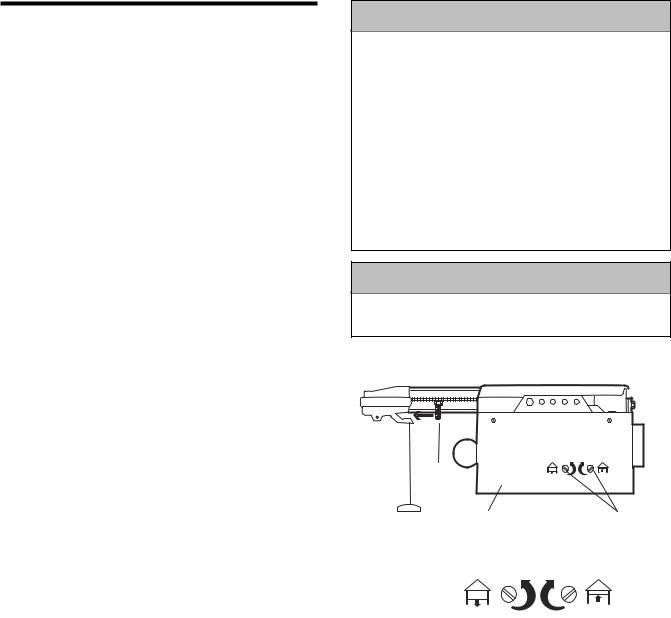
ADJUSTMENT STEP 1
Adjust the UP and DOWN Travel
Limits
Limit adjustment settings regulate the points at which the door will stop when moving up or down.
To operate the opener, press the Door Control push bar. Run the opener through a complete travel cycle.
•Does the door open and close completely?
•Does the door stay closed and not reverse unintentionally when fully closed?
If your door passes both of these tests, no limit adjustments are necessary unless the reversing test fails (Adjustment Step 3, page 22).
Adjustment procedures are outlined below. Read the procedures carefully before proceeding to Adjustment Step 2. Use a screwdriver to make limit adjustments. Run the opener through a complete travel cycle after each adjustment.
NOTE: Repeated operation of the opener during adjustment procedures may cause the motor to overheat and shut off. Simply wait 15 minutes and try again.
NOTE: If anything interferes with the door’s upward travel, it will stop. If anything interferes with the door’s downward travel (including binding or unbalanced doors), it will reverse.
HOW AND WHEN TO ADJUST THE LIMITS
•If the door does not open completely but opens at least five feet:
Increase up travel. Turn the UP limit adjustment screw clockwise. One turn equals 2" of travel.
NOTE: To prevent the trolley from hitting the cover protection bolt, keep a minimum distance of 2-4" between the trolley and the bolt.
•If door does not open at least 5 feet:
Adjust the UP (open) force as explained in Adjustment Step 2.
•If the door does not close completely:
Increase down travel. Turn the down limit adjustment screw counterclockwise. One turn equals 2" of travel.
If door still won't close completely and the trolley bumps into the pulley bracket (page 4), try lengthening the door arm (page 19) and decreasing the down limit.
•If the opener reverses in fully closed position:
Decrease down travel. Turn the down limit adjustment screw clockwise. One turn equals 2" of travel.
 WARNING
Without a properly installed safety reversal system, persons (particularly small children) could be SERIOUSLY INJURED or KILLED by a closing garage door.
•Incorrect adjustment of garage door travel limits will interfere with proper operation of safety reversal system.
•If one control (force or travel limits) is adjusted, the other control may also need adjustment.
•After ANY adjustments are made, the safety reversal system MUST be tested. Door MUST reverse on contact with 1-1/2" high object (or 2x4 laid flat) on floor.
CAUTION
To prevent damage to vehicles, be sure fully open door provides adequate clearance.
2-4"
Cover
Protection
Bolt
Left Side |
Limit |
|
Panel |
Adjustment |
|
|
Screws |
|
|
|
|
|
|
|
Adjustment Label
•If the door reverses when closing and there is no visible interference to travel cycle:
If the opener lights are flashing, the Safety Reversing Sensors are either not installed, misaligned, or obstructed. See Troubleshooting, page 17.
Test the door for binding: Pull the emergency release handle. Manually open and close the door. If the door is binding or unbalanced, call for a trained door systems technician. If the door is balanced and not binding, adjust the DOWN (close) force. See Adjustment Step 2.
20
Loading...