


Visit us at : http://www.lgservice.com
LG
LG
AHU Control Kit / EEV Kit
Installation Manual
Models: PRCKA0
PRLK048A0
IMPORTANT
•Please read this installation manual completely before installing the product.
•Installation work must be performed in accordance with the national wiring standards by authorized personnel only.
•Please retain this installation manual for future reference after reading it thoroughly.
<![endif]>ENGLISH

AHU Control Kit / EEV Kit Installation Manual
TABLE OF CONTENTS
■ Safety Precautions............................................................. |
3 |
■ Installation Scene............................................................... |
4 |
■ Supplies.............................................................................. |
5 |
■ Optional Accessories ......................................................... |
6 |
■ Part Description.................................................................. |
7 |
■ Control Kit (PRCKA0) ................................................................................. |
7 |
■ EEV Kit(PRLK048A0)................................................................................. |
8 |
■ Before Installation .............................................................. |
9 |
■ EEV Kit Installation .......................................................... |
11 |
■ Mechanical installation........................................................................ |
11-12 |
■ Brazing work ....................................................................................... |
13-14 |
■ Electrical work .......................................................................................... |
15 |
■ Control Kit Installation...................................................... |
16 |
■ Mechanical installation ............................................................................. |
16 |
■ Electric wiring work ............................................................................. |
17-19 |
■ Dry contact connection_optional accessory ............................................ |
20 |
■ Thermistors Installation ................................................... |
21 |
■ Pipe thermistors installation................................................................ |
21-23 |
■ Room thermistor....................................................................................... |
24 |
■ Test Operation.................................................................. |
25 |
■ Troubleshooting................................................................ |
26 |
2 AHU Control Kit / EEV Kit
Safety Precautions
Safety Precautions
To prevent injury to the user or other people and property damage, the following instructions must be followed.
■Incorrect operation due to ignoring instruction will cause harm or damage. The seriousness is classified by the following indications.
WARNING |
This symbol indicates the possibility of death or serious injury. |
CAUTION |
This symbol indicates the possibility of injury or damage. |
■ Meanings of symbols used in this manual are as shown below.
Be sure not to do.
Be sure to follow the instruction.
<![endif]>ENGLISH
 WARNING
■ Installation
Don't touch with the |
Use standard |
hands while the power is |
parts(connector). |
on |
|
•There is risk of fire or electric shock.
Use the correctly rated breaker or fuse.
•There is risk of fire or electric shock.
•Do not disassemble or repair the product. There is risk of fire or electric shock.
Do not install, remove, or reinstall the unit by yourself (customer).
•There is risk of fire, electric shock, explosion, or injury.
For electrical work, contact the dealer, seller, a qualified electrician, or an Authorized Service Center.
•Do not disassemble or repair the product. There is risk of fire or electric shock.
■ Operation
When the product is soaked (flooded or submerged), contact an Authorized Service Center.
• There is risk of fire or electric shock.
Be cautious that water could not enter the product.
•There is risk of fire, electric shock, or product damage.
Installation Manual 3
Installation Scene
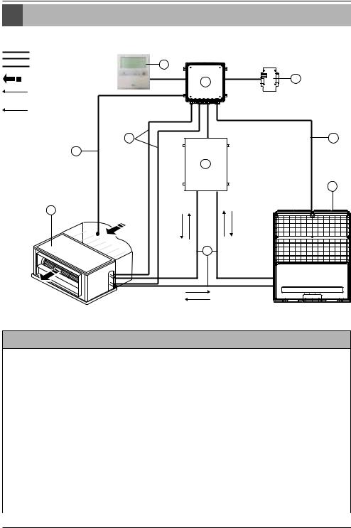
Installation Scene
Signal |
|
|
Pipe |
9 |
|
Thermistor |
|
|
|
|
|
Air flow |
3 |
10 |
Refrigerant flow |
|
|
|
|
|
(Cooling) |
|
|
Refrigerant flow |
|
|
(Heating) |
|
|
7 |
|
6 |
8
4
2
1
5 |
Parts and components
No. |
Name |
Remarks |
|
|
|
1 |
Air Handling Unit |
Field supply |
|
|
|
2 |
Outdoor Unit |
Multi_V |
|
|
|
3 |
AHU Control Kit(PRCKA0) |
- |
|
|
|
4 |
AHU EEV Kit(PRLK048A0) |
- |
|
|
|
5 |
Field piping |
Field supply |
|
|
|
Wiring connections |
|
|
|
|
|
6 |
Control kit wiring |
(Power supply and communication between control kit and outdoor unit) |
|
|
|
7 |
Pipe thermistors (EBG36949304/EBG36949305) |
Evaporator (In/Out) control of Air Handling Unit |
|
|
|
8 |
Room thermistor (EBG36949303) |
Return air control |
|
|
|
9 |
Remote controller(PQRCUSA0) |
Optional accessory |
|
|
|
10 |
Dry contact PCB(PQDSBNGCM0) |
Optional accessory |
|
|
|
4 AHU Control Kit / EEV Kit

Supplies
Supplies
PRCKA0
Components |
AHU Control Kit |
Room thermistor |
Pipe thermistors |
Installation |
Capacity setting |
||||
manual |
option PCB |
||||||||
|
|
|
|
||||||
|
|
|
|
|
|
|
|
|
|
P/NO |
AJT57850901 |
EBG36949303 |
EBG36949304(black) |
MFL50024801 |
EBR52358907/09 |
||||
EBG36949305 (red) |
/10/11/12 |
||||||||
|
|
|
|
|
|
|
|||
|
|
|
|
|
|
|
|
|
|
|
|
|
|
|
|
|
|
|
|
|
|
|
|
|
|
|
|
|
|
|
|
|
|
|
|
|
|
|
|
Shape |
H |
|
|
|
|
|
|
|
|
|
|
|
|
|
|
D |
W |
|
|
|
Quantity(EA) |
|
1 |
1 |
2(Each 1) |
1 |
5(Each 1) |
PRLK048A0 |
|
|
|
|
|
|
Components |
|
|
AHU EEV Kit |
|
Installation manual |
|
P/NO |
|
|
AJT57850801 |
|
MFL50024801 |
|
Shape
W
|
|
H |
D |
|
|
|
|
|
|
|
|
|
|
Quantity(EA) |
|
1 |
|
|
|
1 |
Model Name |
Weight(kg) |
|
Dimension(mm) |
|
POWER |
|
|
|
|
|
|
||
|
NET |
Gross |
W |
H |
D |
|
PRCKA0 |
2.2 |
3.6 |
280 |
135 |
280 |
220~240V/50Hz/1Phase |
PRLK048A0 |
3.1 |
3.6 |
404 |
83 |
217 |
- |
<![endif]>ENGLISH
Installation Manual 5

Optional Accessories
Optional Accessories
Accessories
Components |
Remote controller |
Dry contact PCB |
|
|
|
|
|
Model name |
PQRCUSA0 |
PQDSBNGCM0 |
|
|
|
|
|
|
|
|
|
|
|
|
|
|
|
|
|
Shape
*For further details of the accessories, refer to the manual provided at the time of purchasing the accessories.
6 AHU Control Kit / EEV Kit
Part Description
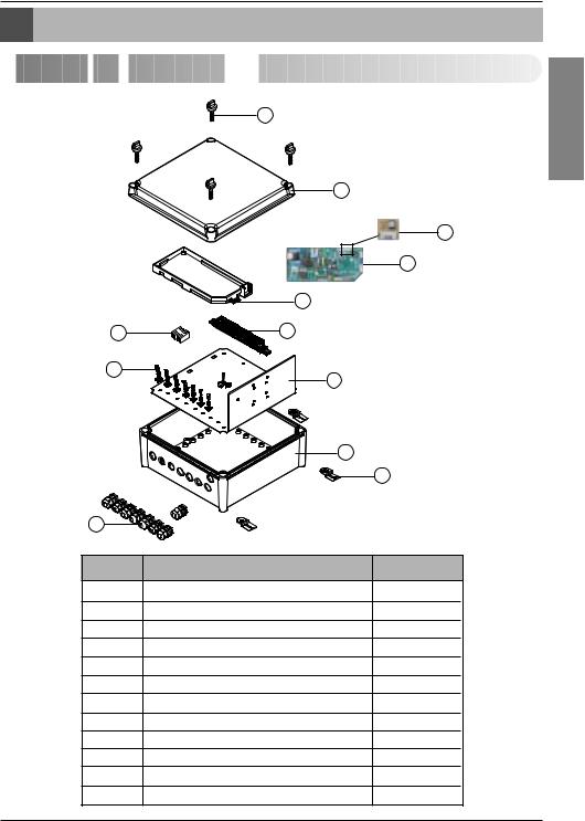
Part Description


 Control
 Kit
Kit
 (PRCKA0)


1
2
CN-OPTION |
4 |
3
5
7 |
6 |
9
8
|
10 |
|
|
|
12 |
11 |
|
|
No. |
Part Name |
Quantity(EA) |
1 |
Plastic (+) bolt |
4 |
2 |
Control box cover |
1 |
3 |
Main PCB |
1 |
4 |
Option PCB(36k) |
1 |
5 |
Main PCB case |
1 |
6 |
Terminal block (communication) |
1 |
7 |
Terminal block (POWER Supply) |
1 |
8 |
Panel |
1 |
9 |
Support Tie wrap |
8 |
10 |
Control box case |
1 |
11 |
Cable gland(2type) |
8 |
12 |
Bracket |
4 |
<![endif]>ENGLISH
Installation Manual 7
Part Description


 EEV
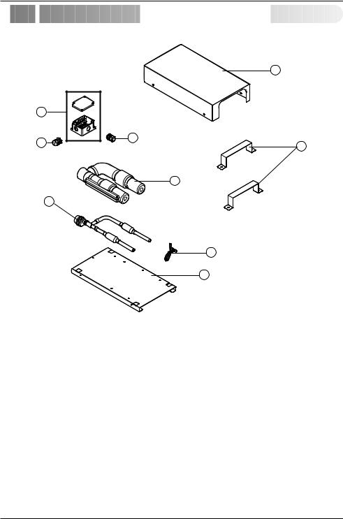
EEV Kit(PRLK048A0)


|
1 |
|
3 |
|
|
4 |
4 |
|
2 |
||
|
5
6
7
8
No. |
Part Name |
Quantity(EA) |
|
|
|
1 |
Panel upper |
1 |
|
|
|
2 |
Bracket |
2 |
|
|
|
3 |
Terminal box |
1 |
|
|
|
4 |
Cable gland |
2 |
|
|
|
5 |
Insulator tube |
1 |
|
|
|
6 |
EEV assembly (EEV, Strainer, Tube) |
1 |
|
|
|
7 |
Support tie wrap |
1 |
|
|
|
8 |
Panel base |
1 |
|
|
|
8 AHU Control Kit / EEV Kit

Before Installation
Before Installation
 CAUTION
■ Don't install or operate the unit in rooms mentioned below.
 Where mineral oil, like cutting oil is present.
 Where the air contains high levels of salt such as air near the ocean.
 Where sulphurous gas is present such as that in areas of hot spring.
 In vehicles or vessels.
 Where voltage fluctuates a lot such as that in factories.
 Where high concentration of vapor spray are present.
 Where machines generating electromagnetic waves are present.
 Where acidic or alkaline vapor is present.
 The option boxes must be installed with entrances downward.
■ Check the mentioned below, when you apply the AHU(Field supply).
 If the AHU (Field supply) provided in the field is exclusively for heating, you must not change the operating mode to cooling on the remote controller. If not, it can cause electric shock, injury or death. If you want to operate in cooling mode, AHU (Field supply) must comply with the following details.
(Following)
- The insulation level of AHU (Field supply) motor must be ‘F’ or above, and the protection level must satisfy ‘IP 54’.
- AHU (Field supply) must have the drain pan installed.
 Fan speed button on the wired remote controller(PQRCUSA0) is not operated.
 For refrigerant piping of outdoor unit, refer to the installation manual supplied with the outdoor unit.
 For installation of the wired remote controller(PQRCUSA0), refer to the manual supplied with the wired remote controller.
 For connection of the Dry contact PCB(PQDSBNGCM0), refer to the manual supplied with the Dry contact PCB(PQDSBNGCM0).
■ AHU Control Kit
 Thermistor cable and remote controller wire should be located at least 50mm away from power supply wires and from wires to the controller. Not following this guideline may result in malfunction due to electrical noise.
 Use only specified wires, and tightly connect wires to the terminals. Keep wiring in neat order so that it does not obstruct other equipment. Incomplete connections could result in overheating, and in worse case electric shock or fire.
<![endif]>ENGLISH
Installation Manual 9
 Loading...