


LG
LG
New Wide Wired Remote Controller
Owner's & Installation Manual
Models: PQRCVSL0
PQRCVSL0QW
IMPORTANT
• Please read this owner's & installation manual completely before installing the product.
• Installation work must be performed in accordance with the national wiring standards by authorized personnel only.
• Please retain this owner's & installation manual for future reference after reading it thoroughly.
P/No.: MFL62129202
PORTUGUÊS кмллдав DEUTSCH FRANÇAIS ESPAÑOL ITALIANO ENGLISH
New Wide Wired Remote Controller Owner’s & Installation Manual
TABLE OF CONTENTS
Safety Precaution ......................................................................................................................................... |
3 |
|
Part Description............................................................................................................................................ |
4 |
|
Installation instruction................................................................................................................................. |
5 |
|
Group control.............................................................................................................................................. |
7 |
|
Installer Setting - How to enter installer setting mode................................................................................ |
8 |
|
Installer Setting - Test Run Mode............................................................................................................. |
11 |
|
Installer Setting - Setting Address of Central Control............................................................................... |
12 |
|
Installer Setting - E.S.P. ........................................................................................................................... |
13 |
|
Installer Setting - Thermistor .................................................................................................................... |
15 |
|
Installer Setting - Ceiling Height Selection ............................................................................................... |
16 |
|
Installer Setting - Static Pressure Setting................................................................................................. |
17 |
|
Installer Setting - Remote Controller Master/Slave Setup ....................................................................... |
18 |
|
Installer Setting - Override Master/Slave Setting ..................................................................................... |
19 |
|
Installer Setting - Dry Contact Mode Setting ............................................................................................ |
20 |
|
Installer Setting - Zone State.................................................................................................................... |
21 |
|
Installer Setting - Celsius / Fahrenheit Switching..................................................................................... |
22 |
|
Installer Setting - Zone Type Setting........................................................................................................ |
23 |
|
Installer Setting - Zone Number Setting ................................................................................................... |
24 |
|
Installer Setting - Emergency Heater Setting .......................................................................................... |
25 |
|
Installer Setting - Option Function Setting................................................................................................ |
27 |
|
Owner's instruction.................................................................................................................................... |
28 |
|
Standard Operation - Standard Cooling................................................................................................... |
28 |
|
Standard Operation - Power Cooling ....................................................................................................... |
29 |
|
Standard Operation - Heating Mode ........................................................................................................ |
29 |
|
Standard Operation - Dehumidification Mode .......................................................................................... |
30 |
|
Standard Operation - Fan Mode............................................................................................................... |
30 |
|
Standard Operation - Auto Operation Mode ............................................................................................ |
31 |
|
Standard Operation - Temperature Setting/Room Temperature Check................................................... |
32 |
|
Standard Operation - Airflow Setting........................................................................................................ |
33 |
|
Sub function - Direct Wind / Indirect Wind .............................................................................................. |
34 |
|
Sub function - Plasma Purification ........................................................................................................... |
36 |
|
Sub function - Humidifier.......................................................................................................................... |
37 |
|
Sub function - Electric Heater................................................................................................................... |
38 |
|
Sub function - Energy-Saving Cooling Operation..................................................................................... |
39 |
|
Sub function - Robot Cleaning Manual Setup .......................................................................................... |
40 |
|
Function setting - Child Lock.................................................................................................................... |
41 |
|
Function setting - Robot Cleaning Automatic Setup................................................................................. |
42 |
|
Function setting - Filter Sign Clear........................................................................................................... |
43 |
|
Function setting - Elevation Grill............................................................................................................... |
44 |
|
Function setting - Vane Angle Control...................................................................................................... |
45 |
|
Function Setting - Change Temp ............................................................................................................. |
46 |
|
Function setting - Zone Control................................................................................................................ |
47 |
|
Function |
setting - Changing Current Time .............................................................................................. |
48 |
Function |
setting - Auto Cleaning ............................................................................................................. |
50 |
Programming - Simple Reservation ......................................................................................................... |
51 |
|
Programming - Sleep Reservation ........................................................................................................... |
52 |
|
Programming - ON Reservation............................................................................................................... |
53 |
|
Programming - OFF Reservation ............................................................................................................. |
55 |
|
Programming - Weekly Reservation......................................................................................................... |
57 |
|
Programming - Holiday Reservation ........................................................................................................ |
59 |
|
Ventilation Product User Manual - Interlinked Air conditioner and Ventilation ......................................... |
60 |
|
Ventilation Product User Manual - Interlinked operation with general ventilation ................................... |
61 |
|
Manual Conversion - Pressing ‘Ventilation’ button in ventilation mode will manually convert.................. |
62 |
|
Ventilation Product User Manual - Interlinked Operation with Direct Expansion Ventilation.................... |
63 |
|
Ventilation Product User Manual - Single Operation with Direct Expansion Ventilation .......................... |
64 |
|
Ventilation Product Additional Operations - Fast / Power Saving ............................................................ |
65 |
|
Ventilation Product Function Settings ...................................................................................................... |
66 |
|
Ventilation Product Reservations Settings ............................................................................................... |
67 |
|
Ventilation Product Installer Setting Functions - Entering Method ........................................................... |
68 |
|
Different mode drive ................................................................................................................................ |
69 |
|
Checkups before reporting breakdown .................................................................................................... |
70 |
|
2 New Wide Wired Remote Controller
|
Safety Precaution |
|
|
|
|
|
ENGLISH |
|
|
|
|
|
Safety Precaution |
|
|
|
|
|
|
• The installation requires expert skills, and it should be installed by the service center or other shops specialized |
|
|
|
in the installation and recognized by our company. |
|
|
|
• For all the problems arising after installation by someone who has no relevant qualifications, our company will |
|
|
|
not provide free service. |
|
|
|
• The following safety cautions are provided to prevent unexpected dangers or losses. |
|
|
|
WARNING : If the user does not follow the mandatory items, it may result in serious injury or death. |
|
|
|
CAUTION : If the user does not follow the mandatory items, it may cause personal injury or property |
|
|
|
|
damage. |
|
|
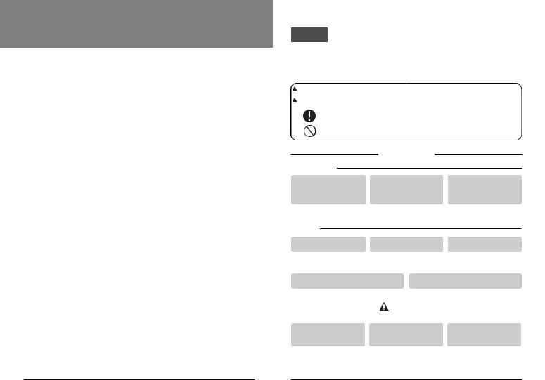
:Warning and Caution are to call the user’s attention to the possible danger. Read and follow them carefully in order to prevent a safety accident.
:Warning and Caution are indicated in this guide and the product itself to help protect the users from danger.
 WARNING
■ Installation
Be sure to request to the service center or installation specialty store when installing products.
•It will cause fire or electric shock or explosion or injury.
Request to the service center or installation specialty store when reinstalling the installed product.
•It will cause fire or electric shock or explosion or injury.
Do not disassemble, fix, and modify products randomly.
• It will cause fire or electric shock.
■ In-use
|
Do not place flammable |
Do not allow water to run |
Do not give the shock to the |
||||
|
stuffs close to the product. |
into the product. |
product. |
||||
|
• It will cause fire. |
• It will cause electric shock or |
• It will cause breakdown when |
||||
|
|
|
breakdown. |
|
|
giving the shock to the product. |
|
|
Request to the service center or installation |
Do not give the shock using sharp and |
|||||
|
specialty store when the product becomes wet. |
pointed objects. |
|||||
|
• It will cause fire or electric shock. |
|
|
• It will cause breakdown by damaging parts. |
|||
|
|
|
|
|
|
|
|
|
|
|
|
CAUTION |
|
|
|
|
|
|
|
|
|
||
|
■ In-use |
|
|
|
|
|
|
|
|
|
|
|
|
|
|
|
|
|
|
|
|
||
|
|
|
|
|
|
|
|
|
Do not clean using the |
Do not press the screen |
Do not touch or pull the lead |
||||
|
powerful detergent like |
using powerful pressure or |
wire with wet hands. |
||||
|
solvent but use soft cloths. |
select two buttons. |
|
||||
|
• It will cause fire or product |
• It will cause product breakdown or |
• It will cause product breakdown or |
||||
|
deformation. |
malfunction. |
|
|
electric shock. |
||
Owner’s & Installation Manual 3
Part Description
Part Description
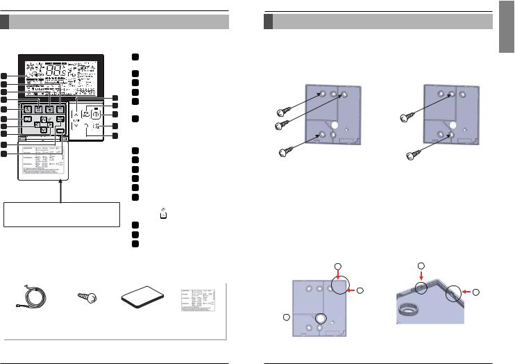
Name and Function of Remote Controller
1 |
|
|
10 |
|
|
9 |
|
|
8 |
2 |
|
|
||
7 |
3 |
|
4 |
||
11 |
||
|
||
12 |
5 |
|
13 |
6 |
|
|
||
14 |
|
|
15 |
|
Please attach the inform label inside of the door. Please choose proper language depend on your country.
1OPERATION INDICATION SCREEN
2 SET TEMPERATURE BUTTON
3 FAN SPEED BUTTON
4 ON/OFF BUTTON
5OPRATION MODE SELECTION BUTTON
6WIRELESS REMOTE CONTROLLER RECEIVER
•Some products don't receive the wireless signals.
7 AIR FLOW BUTTON
8 SUBFUNCTION BUTTON
9 FUNCTION SETTING BUTTON
10VENTILATION BUTTON
11RESERVATION
12UP,DOWN,LEFT,RIGHT BUTTON
•To check the indoor temperature, press 
 button.
13ROOM TEMPERATURE BUTTON
14SETTING/CANCEL BUTTON
15EXIT BUTTON
Some functions may not be operated and displayed depending on the product type.
Accessory
Connection Cable |
Screw |
Owner's / Installation |
Inform label |
(1EA, 10m) |
(4 EA) |
manual |
(8EA-8Languages) |
|
|||
|
|
|
|
Installation instruction
Installation instruction
1.Please fix tightly using provided screw after placing remote controller setup board on the place where you like to setup.
-Please set it up not to bend because poor setup could take place if setup board bends. Please set up remote controller board fit to the reclamation box if there is a reclamation box.
-Install the product so as not to make a gap with the wall side and to prevent shaking after the installation.
2.Can set up Wired remote controller cable into three directions.
-Setup direction: the surface of wall reclamation, upper, right
-If setting up remote controller cable into upper and right side, please set up after removing remote controller cable guide groove.
Remove guide groove with long nose.
Reclamation to the surface of the wall
Upper part guide groove
Right part guide groove
2 |
2 |
3 |
3 |
1 
<Wire guide grooves>
ENGLISH
4 New Wide Wired Remote Controller |
Owner’s & Installation Manual 5 |
Installation instruction
3.Please fix remote controller upper part into the setup board attached to the surface of the wall, as the picture below, and then, connect with setup board by pressing lower part.
-Please connect not to make a gap at the remote controller and setup board’s upper and lower, right and left part.
-Before assembly with the installation board, arrange the Cable not to interfere with circuit parts.
<Connecting order>
Wall |
|
|
|
Wall |
|
|
|
||
Side |
|
|
|
Side |
|
|
|
|
|
When separating remote controller from setup board, as the picture below, after inserting into the lower separating hole using screw driver and then, spinning clockwise, remote controller is separated.
- There are two separating holes. Please individually separate one at a time.
- Please be careful not to damage the inside components when separating.
<Separating order>
Wall |
|
|
|
Wall |
|
|
|
||
|
|
|||
Side |
|
|
|
Side |
|
|
|
|
|
4. Please connect indoor unit and remote controller using connection cable.
12V |
Red |
|
|
Signal |
Yellow |
Please check if connector is normally connected. |
|
|
|||
GND |
Black |
Indoor |
|
Unit side |
|||
|
|
||
|
|
Connecting cable |
 CAUTION
•Installation work must be performed in accordance with the national wiring standards by authorized personnel only.
•Installations must comply with the applicable local/national or international standards.
•Apply totally enclosed noncombustible conduit (metal raceway) in case of local electric & building code require plenum cable usage.
5.Please use extension cable if the distance between wired remote controller and indoor unit is more than 10m.
 CAUTION
When installing the wired remote controller, do not bury it in the wall. (It can cause damage in the temperature sensor.)
Do not install the cable to be 50m or above. (It can cause communication error.)
•When installing the extension cable, check the connecting direction of the connector of the remote controller side and the product side for correct installation.
•If you install the extension cable in the opposite direction, the connector will not be connected.
•Specification of extension cable: 2547 1007 22# 2 core 3 shield 5 or above.
Installation instruction
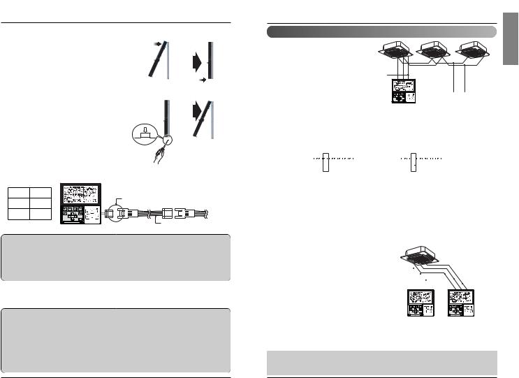
Group control
1.When installing more than 2 units of air conditioner to one wired remote controller, please connect as the right figure.
•If it is not event communication indoor unit, set the unit as slave.
•Check for event communication through the product manual.
GND  Signal wire
12V
GND Signal wire
When controlling multiple indoor units with event communication function with one remote controller, you must change the master/slave setting from the indoor unit.
-Indoor units, the master/slave configuration of the product after completion of indoor unit power ‘OFF’ and then ‘ON’ the power after 1 minutes elapsed sign up.
-For ceiling type cassette and duct product group, change the switch setting of the indoor PCB.
|
ON |
|
ON |
|||||||||||||||||
|
|
|
|
|
|
|
|
|
|
|
|
|
|
|
|
|
|
|
|
|
|
|
|
|
|
|
|
|
|
|
|
|
|
|
|
|
|
|
|
|
|
|
1 2 3 4 5 6 7 8 |
|
|
1 2 3 4 5 6 7 8 |
|
|||||||||||||||
#3 switch OFF: Master |
|
|
#3 switch ON: Slave |
|||||||||||||||||
(Factory default setting) |
|
|
|
|
|
|
|
|
|
|
|
|||||||||
-For wall-mount type and stand type product, change the master/slave setting with the wireless remote controller. (Refer to wireless remote controller manual for detail)
When installing 2 remote controllers to one indoor unit with event communication function, set the master/slave of the remote controller. (Refer to remote controller master/slave selection)
When controlling the group, some functions excluding basic operation setting, fan level Min/Mid/Max, remote controller lock setting and time setting may be limited.
2.When installing more than 2 wired remote controllers to one air conditioner, please connect as the right picture.
•When installing more than 2 units of wired remote controller to one air conditioner, set one wired remote controller as master and the others all as slaves, as shown in the right picture.
•You cannot control the group as shown in the right for some products.
•Refer to the product manual for more detail.
GND |
|
|
|
|
|
|
|
|
|
|
|
|
|
|
GND |
|
|
|
|
|
|
|
|
|
|
|
|
|
|||
Signal wire |
|
|
|
|
|
|
|
|
|
|
|
|
|
||
12V |
|
|
|
|
|
|
|
|
|
|
|
|
|
|
Signal wire |
|
|
|
|
|
|
|
|
|
|
|
|
|
12V |
||
|
|
|
|
|
|
|
|
|
|
|
|
|
|
|
|
|
|
|
B |
Y |
R |
|
|
|
B Y R |
||||||
|
|
|
|
|
|
|
|
|
|
|
|
|
|
|
|
|
|
|
|
|
|
|
|
|
|
|
|
|
|
|
|
MASTER SLAVE
<When simultaneously connecting 2 sets of wired remote controller>
•When controlling in groups, set the master/slaver of the remote controller. Refer to Installer setting section on how to set master/slave for more detail.
ENGLISH
6 New Wide Wired Remote Controller |
Owner’s & Installation Manual 7 |
Installation instruction
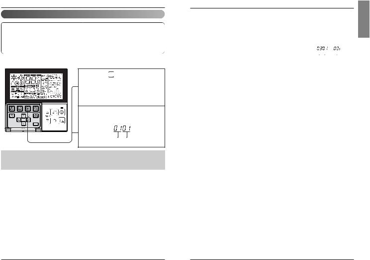
Installer Setting -How to enter installer setting mode
 CAUTION
Installer setting mode is to set the detail function of the remote controller.
If the installer setting mode is not set correctly, it can cause problems to the product, user injury or property damage. This must be set by an certificated installer, and any installation or change that is carried out by a non-certificated person should be responsible for the results. In this case, free service cannot be provided.
1 If pressing 

 button long for 3 seconds, it enters into remote controller setter setup mode.
- If pressing once shortly, it enters into user setup mode. Please press more than 3 seconds for sure.
2 When you enter the setting mode initially, Function code is displayed on the bottom of the LCD screen.
Function Code |
Value |
•Some categories of the menu may not be displayed according to the function of the product, or the menu name may be different.
Installation instruction
<Installer Setting Code Table>
1) General air-conditioner product
No. |
Function |
Code |
|
|
Value |
|
|
|
|
|
|
|
|
|
|
|
1 |
Test Run |
01 |
01:Set |
|
|
|
|
|
|
|
|
|
|
|
|
|
2 |
Address Setting |
02 |
00~FF : Address |
|
|
|
|
|
|
|
|
|
|
|
||
|
|
|
<ESP Step> |
<ESP Value> |
|
<Example> |
||||||||||
|
|
|
01:VeryLow |
0 ~ 255 |
|
|
|
|
|
|
|
|
|
|
||
3 |
E.S.P. Value |
03 |
02:Low |
|
|
|
|
|
|
|
|
|
|
|
|
|
03:Med |
|
|
|
|
|
|
|
|
|
|
|
|
||||
|
|
|
04:High |
|
Function Code ESP step |
|
ESP value |
|||||||||
|
|
|
|
|
|
|
|
|
|
|
|
|
|
|
||
|
|
|
05:Very High |
|
|
|
|
|
|
|
|
|
|
|
||
|
|
|
01:Remo |
|
|
|
|
|
|
|
|
|
|
|
|
|
4 |
Thermistor |
04 |
02:Indoor |
|
|
|
|
|
|
|
|
|
|
|
|
|
|
|
|
03:2TH |
|
|
|
|
|
|
|
|
|
|
|
|
|
|
|
|
01:Low |
|
|
|
|
|
|
|
|
|
|
|
|
|
5 |
Ceiling Height |
05 |
02:Med |
|
|
|
|
|
|
|
|
|
|
|
|
|
03:High |
|
|
|
|
|
|
|
|
|
|
|
|
||||
|
|
|
|
|
|
|
|
|
|
|
|
|
|
|
||
|
|
|
04:Very High |
|
|
|
|
|
|
|
|
|
|
|
||
|
|
|
01:V-H |
|
|
|
|
|
|
|
|
|
|
|
|
|
6 |
Static Pressure |
06 |
02:F-H |
|
|
|
|
|
|
|
|
|
|
|
|
|
03:V-L |
|
|
|
|
|
|
|
|
|
|
|
|
||||
|
|
|
|
|
|
|
|
|
|
|
|
|
|
|
||
|
|
|
04:F-L |
|
|
|
|
|
|
|
|
|
|
|
|
|
7 |
Master Setting |
07 |
00:Slave If only “Plus1” series models |
|
00 : Group setting |
|||||||||||
01:Master |
|
01 : Single setting |
|
|
|
|
||||||||||
|
|
|
|
|
|
|
|
|||||||||
8 |
Override Setting |
08 |
00:Slave |
|
|
|
|
|
|
|
|
|
|
|
|
|
01:Master |
|
|
|
|
|
|
|
|
|
|
|
|
||||
|
|
|
|
|
|
|
|
|
|
|
|
|
|
|
||
9 |
Dry Contact |
09 |
00:Auto-Off |
|
|
|
|
|
|
|
|
|
|
|
||
01:Auto-On |
|
|
|
|
|
|
|
|
|
|
|
|||||
|
|
|
|
|
|
|
|
|
|
|
|
|
|
|||
10 |
Release 3 Min. |
10 |
01:Set |
|
|
|
|
|
|
|
|
|
|
|
|
|
Delay |
|
|
|
|
|
|
|
|
|
|
|
|
||||
|
|
|
|
|
|
|
|
|
|
|
|
|
|
|
||
11 |
Zone State |
11 |
01:Variable |
|
|
|
|
|
|
|
|
|
|
|
||
02:Fixed |
|
|
|
|
|
|
|
|
|
|
|
|
||||
|
|
|
|
|
|
|
|
|
|
|
|
|
|
|
||
12 |
Celsius |
12 |
00:Celsius |
(Optimized only for U.S.A) |
|
|
|
|
||||||||
Fahrenheit Switching |
01:Fahrenheit |
|
|
|
|
|||||||||||
|
|
|
|
|
|
|
|
|
|
|
|
|
||||
13 |
Zone Type |
13 |
00:Zone Controller |
|
|
|
|
|
|
|
|
|
|
|
||
01:Damper Controller |
|
|
|
|
|
|
|
|
|
|
||||||
|
|
|
|
|
|
|
|
|
|
|
|
|
||||
14 |
Zone Number |
14 |
02~04(Zone number) |
|
|
|
|
|
|
|
|
|
|
|||
|
|
|
Select mode |
Setup Low Ambient Heating Operation |
|
|
|
|
|
|
Setup FAN Speed |
|||||
|
Emergency Heater |
|
00 : not use |
0 : not use |
|
|
|
|
|
|
|
0 : fan off |
||||
15 |
18 |
01 : use |
1 : use – compressor off(0 /-18 )/on(5 /-15 ) |
1 : fan on |
||||||||||||
Setting |
||||||||||||||||
|
|
|
2 : use – compressor off(5 /-15 )/on(10 /-12 ) |
|
|
|
|
|||||||||
|
|
|
|
|
|
|
|
|||||||||
|
|
|
|
3 : use – compressor off(10 /-12 )/on(15 /-9 ) |
|
|
|
|
||||||||
|
|
|
|
|
|
|
|
|
|
|
|
|
|
|
|
|
16 |
Plasma |
20 |
|
|
|
|
|
|
|
|
|
|
|
|
|
|
17 |
Electric heater |
21 |
00: Not Installed |
|
|
|
|
|
|
|
|
|
|
|
||
18 |
Humidifier |
22 |
|
|
|
|
|
|
|
|
|
|
|
|||
01: Installed |
|
|
|
|
|
|
|
|
|
|
|
|||||
19 |
Elevation Grill |
23 |
|
|
|
|
|
|
|
|
|
|
|
|||
|
|
|
|
|
|
|
|
|
|
|
|
|
||||
20 |
Ventilation Kit |
24 |
|
|
|
|
|
|
|
|
|
|
|
|
|
|
21 |
Auxiliary Heater |
25 |
|
|
|
|
|
|
|
|
|
|
|
|
|
|
Some contents may not be displayed depending on the product function
ENGLISH
8 New Wide Wired Remote Controller |
Owner’s & Installation Manual 9 |
Installation instruction
2) General Ventilation product
No. |
Function |
Code |
|
|
Value |
|
|
|
|
|
|
|
||
1 |
Test Run |
01 |
01 |
: Test Run Setup |
|
|
|
|
|
|
|
|
|
|
2 |
Address Setting |
02 |
00~FF : Address of Central Control |
|
|
|
|
|
|
|
||||
|
|
|
|
|
|
|
|
|
|
|
|
|
||
3 |
SA(Supply Air) ESP |
03 |
<ESP level> |
<ESP value> |
<Example> |
|||||||||
|
|
|
01 |
: Low |
0~255 |
|
|
|
|
|
|
|
|
|
4 |
EA(Exhaust Air) ESP |
04 |
02 |
: High |
|
|
|
|
|
|
|
|
|
|
|
|
|
03 |
: Super High |
Function Code |
|
ESP step |
ESP value |
||||||
|
|
|
|
|
|
|
|
|
|
|
|
|
||
5 |
Product Direction |
05 |
01 |
: Normal |
|
|
|
|
|
|
|
|
|
|
02 |
: Opposite |
|
|
|
|
|
|
|
|
|
|
|||
|
|
|
|
|
|
|
|
|
|
|
|
|
||
6 |
Quick Refresh Priority |
06 |
01 |
: Supply Air First |
|
|
|
|
|
|
|
|
|
|
02 |
: Exhaust Air First |
|
|
|
|
|
|
|
|
|
|
|||
|
|
|
|
|
|
|
|
|
|
|
|
|
||
7 |
Master Setting |
07 |
00 |
: Slave |
|
|
|
|
|
|
|
|
|
|
01 |
: Master |
|
|
|
|
|
|
|
|
|
|
|||
|
|
|
|
|
|
|
|
|
|
|
|
|
||
8 |
Override Setting |
08 |
00 |
: Slave |
|
|
|
|
|
|
|
|
|
|
01 |
: Master |
|
|
|
|
|
|
|
|
|
|
|||
|
|
|
|
|
|
|
|
|
|
|
|
|
||
9 |
Dry Contact |
09 |
00 |
: Auto-Off |
|
|
|
|
|
|
|
|
|
|
01 |
: Auto-On |
|
|
|
|
|
|
|
|
|
|
|||
|
|
|
|
|
|
|
|
|
|
|
|
|
||
10 |
Release Of 3 Minute Delay |
10 |
01 |
: Set |
|
|
|
|
|
|
|
|
|
|
11 |
Zone State |
11 |
01 |
: Variable |
|
|
|
|
|
|
|
|
|
|
02 |
: Fixed |
|
|
|
|
|
|
|
|
|
|
|||
|
|
|
|
|
|
|
|
|
|
|
|
|
||
12 |
Humidification for Singular |
13 |
00 |
: Not in Use |
|
|
|
|
|
|
|
|
|
|
Ventilation |
01 |
: Use |
|
|
|
|
|
|
|
|
|
|
||
|
|
|
|
|
|
|
|
|
|
|
|
|||
13 |
Humidification for Heat Mode |
14 |
00 |
: Automatic |
|
|
|
|
|
|
|
|
|
|
Ventilation |
01 |
: Manual |
|
|
|
|
|
|
|
|
|
|
||
|
|
|
|
|
|
|
|
|
|
|
|
|||
Some contents may not be displayed depending on the product function
|
Installation instruction |
|
|
|
|
|
ENGLISH |
|
|
|
|
For details related to this operation, refer to the product manual. |
|
|
|
Installer Setting -Test Run Mode |
|
|
|
After installing the product, you must run a Test Run mode. |
|
|
|
|
|
|
|
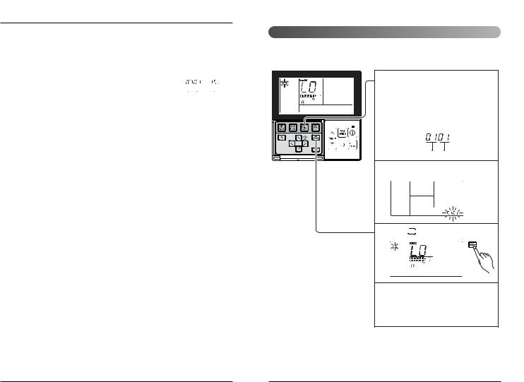
1 If pressing  button long for 3 seconds, it enters into remote controller setter setup mode.
- If pressing once shortly, it enters into user setup mode. Please press more than 3 seconds for sure.
- Please cancel the right and left of wind direction for RAC product.
Function Code Set
2 Setup figure '01' blinks at the lower part of indication window.
3 Press 
 button to start.
4 During the test run, pressing the below button will exit the test run.
-Select operation, temperature up/down, wind flow control, wind direction, start/stop button.
10 New Wide Wired Remote Controller |
Owner’s & Installation Manual 11 |

Installation instruction
Installer Setting - Setting Address of Central Control
It's the function to use for connecting central control.
Please refer to central controller manual for the details
|
If pressing |
button long for 3 |
1 seconds, it enters into remote |
||
|
controller setter setup mode. |
|
|
- If pressing once shortly, it enters |
|
|
into user setup mode. Please press |
|
|
more than 3 seconds for sure. |
|
2 |
If entering into address setup mode by using |
|
button, it indicates as picture below. |
||
|
|
Indoor No. |
|
|
Group No |
|
|
Function Code |
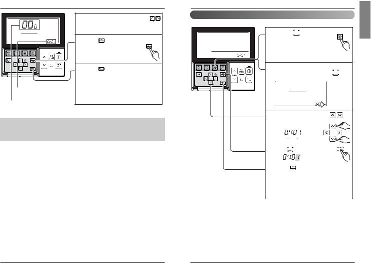
3 Set Group No. by pressing 
 button.(0~F)
4 Move to Indoor No. setting option by pressing 


 button.
5 Setbutton.Indoor No. by pressing 


6 Press 

 button to save.
7 Pressing 


 button will exit settings mode.After setup, it automatically gets out of
setup mode if there is no button input for 25 seconds.
When exiting without pressing set button, the manipulated value is not reflected.
Installation instruction
Installer Setting -E.S.P.
This is the function that decides the strength of the wind for each wind level and because this function is to make the installation easier.
•If you set ESP incorrectly, the air conditioner may malfunction.
•This setting must be carried out by a certificated-technician.
|
|
If pressing |
button long for 3 |
|
|
1 seconds, it enters into remote |
|
||
|
|
controller setter setup mode. |
|
|
|
|
- If pressing once shortly, it enters |
|
|
|
|
into user setup mode. Please press |
|
|
|
|
more than 3 seconds for sure. |
|
|
|
2 |
If entering into ESP setup mode by using |
||
|
button, it indicates as the picture |
|||
|
|
below. |
|
|
|
|
|
ESP step |
|
|
|
|
Function Code |
ESP value |
Function code, |
3 |
Select ESP fan step by pressing |
|
|
ESP code |
|
|||
button. (01: very low, 02: low, |
||||
ESP value |
|
03: medium, 04: high, 05: very high) |
||
|
|
|
|
|
|
4 |
Move to ESP value setting by pressing |
||
|
button. |
|
|
|
|
|
(It is 000 when delivering |
|
|
|
|
from the warehouse.) |
|
|
|
5 Press |
button to setup ESP value. |
||
|
(It is possible to setup ESP |
|
||
|
value from 1 to 255, and 1 is |
|
||
|
the smallest and 255 is the |
|
||
|
biggest.) |
|
|
|
•When setting ESP value on the product without very weak wind or power wind function, it may not work.
ENGLISH
12 New Wide Wired Remote Controller |
Owner’s & Installation Manual 13 |
Installation instruction |
|
|
|
Select ESP fan step again by using |
|
6 button and setup ESP value, as No. 4 |
||
|
and 5, that corresponds each wind flow |
|
7 Press |
button to save. |
|
8 |
Press |
button to exit. |
After setup, it automatically gets out of |
||
|
setup mode if there is no button input |
|
|
for 25 seconds. |
|
Function code, |
When exiting without pressing set |
|
ESP code |
button, the manipulated value is not |
|
|
reflected. |
|
ESP value |
|
|
•Please be careful not to change the ESP value for each fan step.
•It does not work to setup ESP value for very low/power step for some products.
•ESP value is available for specific range belongs to the product.
Installation instruction
Installer Setting -Thermistor
This is the function to select the temperature sensor to judge the room temperature.
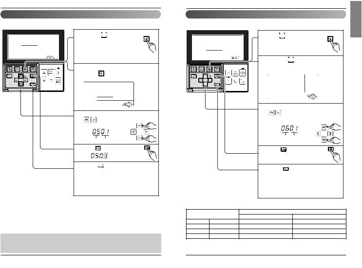
1 If pressing 
 button long for 3 seconds, it enters into remote
controller setter setup mode. - If pressing once shortly, it enters
into user setup mode. Please press more than 3 seconds for sure.
2 If moving to room temperature perception sensor selection menu by pressing 
 button, it indicates as picture below.
|
|
|
|
Set Thermistor value by pressing |
||||||||||||||||
|
|
|
|
3 button. (01: Remote Controller, |
||||||||||||||||
|
|
|
|
02: Indoor, 03: 2TH) |
||||||||||||||||
|
|
|
|
|
|
|
|
|
|
|
|
|
|
|
|
|
|
|
|
|
|
|
|
|
Function Code |
|
Thermistor setting |
||||||||||||||
|
|
|
|
|
|
|
|
|
|
|
|
|
|
|
|
|
|
|
|
|
|
|
|
|
4 Press |
|
|
|
button to save. |
|
|
|
|
|
|
||||||
|
|
|
|
|
|
|
|
|
|
|
|
|
||||||||
|
|
|
|
|
|
|||||||||||||||
|
|
|
|
|
|
|
|
|
|
|
||||||||||
|
|
|
|
|
|
|
|
|
|
|
|
|
|
|
|
|
|
|
||
|
|
|
|
Pressing |
|
|
button will exit settings mode. |
|||||||||||||
|
|
|
|
|
|
|||||||||||||||
|
|
|
|
5 After setup, |
it automatically gets out of |
|||||||||||||||
|
|
|
|
setup mode if there is no button input for |
||||||||||||||||
|
|
|
|
25 seconds. |
||||||||||||||||
|
|
|
|
When exiting without pressing set button, |
||||||||||||||||
|
|
|
|
the manipulated value is not reflected. |
||||||||||||||||
<Thermistor Table> |
|
|
|
|
|
|
|
|
|
|
|
|
|
|
|
|
|
|
||
|
|
|
|
|
|
|
|
|
|
|
|
|
|
|
|
|
|
|||
|
|
|
|
|
|
|
|
|
|
|||||||||||
Temperature sensor selection |
|
|
|
|
|
|
Function |
|||||||||||||
01 |
Remote controller |
Operation in remote controller temperature sensor |
||||||||||||||||||
02 |
Indoor unit |
Operation in indoor unit temperature sensor |
||||||||||||||||||
|
|
Cooling |
Operation of higher temperature by comparing indoor unit's and wired |
|||||||||||||||||
|
|
remote controller’s temperature. |
||||||||||||||||||
03 |
2TH |
|
(There are products that operate at a lower temperature.) |
|||||||||||||||||
|
|
Heating |
Operation of lower temperature by comparing indoor unit's and wired remote |
|||||||||||||||||
|
|
controller's temperature. |
|
|
|
|
|
|
|
|
|
|
|
|
||||||
|
|
|
|
|
|
|
|
|
|
|
|
|
|
|
||||||
|
|
|
|
|
|
|
|
|
|
|
|
|
|
|
|
|
|
|
|
|
The function of 2TH has different operation characteristics according to the product.
ENGLISH
14 New Wide Wired Remote Controller |
Owner’s & Installation Manual 15 |
Installation instruction
Installer Setting -Ceiling Height Selection
This function is to adjust FAN Airflow rate according to ceiling height (For ceiling type product)
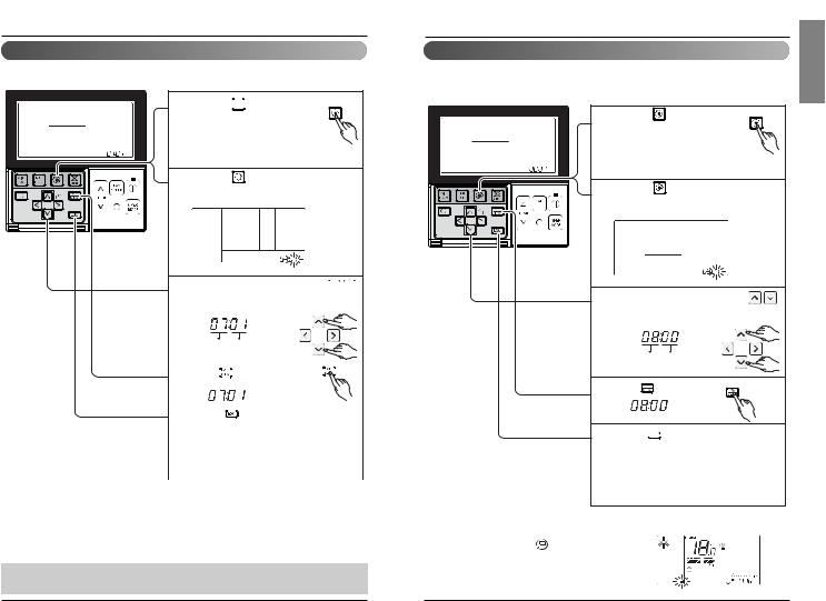
1 If pressing 
 button long for 3 seconds, it enters into remote
controller setter setup mode. - If pressing once shortly, it enters
into user setup mode. Please press more than 3 seconds for sure.
If moving to ceiling height selection menu by |
|
2 pressing |
button, it indicates as picture |
below.
3 |
Select ceiling height value by pressing |
|
|
button. (01:Low, 02:Medium, |
|
|
03:High, 04:Very high) |
|
Function Code |
Thermistor setting |
|
4 |
Press |
button to save. |
Pressing 


 button will exit settings mode. 5 After setup, it automatically gets out of
setup mode if there is no button input for 25 seconds.
When exiting without pressing set button, the manipulated value is not reflected.
<Ceiling Height Selection Table>
|
Ceiling Height Level |
Description |
01 |
Low |
Decrease the indoor airflow rate 1 step from standard level |
02 |
Medium |
Set the indoor airflow rate as standard level |
03 |
High |
Increase indoor airflow rate 1 step from standard level |
04 |
Very high |
Increase indoor airflow rate 2 steps from standard level |
•Ceiling height setting is available only for some products.
•Ceiling height of ‘Very high’ function may not exist depending on the indoor unit.
•Refer to the product manual for more details.
Installation instruction
Installer Setting -Static Pressure Setting
This function is applied to only duct type. Setting this in other cases will cause malfunction.
1 Press 
 button for 4 seconds to enter the installer setting mode until timer segment displays “01:01”.
2 If pressing 
 button repeatedly, it moves to static pressure selection menu as picture below.
|
|
3 |
Select static pressure by pressing |
||
|
|
|
button. |
||
|
|
|
(01:V-H, 02:F-H, 03:V-L, 04:F-L) |
||
|
|
|
Function Code |
Pressure |
|
|
|
4 Press |
|
button to save. |
|
|
|
5 |
Pressing |
|
button will exit settings mode. |
|
|
After setup, it automatically gets out of |
|||
|
|
|
setup mode if there is no button input for |
||
|
|
|
25 seconds. |
||
|
|
|
When exiting without pressing set button, |
||
|
|
|
the manipulated value is not reflected. |
||
<Static Pressure Setting Table> |
|
|
|
|
|
Pressure selection |
|
|
Function |
||
Zone state |
|
ESP standard value |
|||
|
|
|
|||
01 |
V-H |
Variable |
|
High |
|
02 |
F-H |
Fixed |
|
High |
|
03 |
V-L |
Variable |
|
Low |
|
04 |
F-L |
Fixed |
|
Low |
|
ENGLISH
16 New Wide Wired Remote Controller |
Owner’s & Installation Manual 17 |
Installation instruction
Installer Setting-Remote Controller Master/Slave Setup
It is a function for settings in group control, or 2-remote controller control.
1 If pressing 
 button long for 3 seconds, it enters into remote
controller setter setup mode. - If pressing once shortly, it enters
into user setup mode. Please press more than 3 seconds for sure.
2 If pressing  button repeatedly, it moves to master/slave selection menu as picture below.
3 Selectbutton.Master/ Slave by pressing 


 (00: Slave, 01: Master)
|
|
Function Code |
|
|
Master/Slave value |
|
||||||||
|
|
|
|
|
|
|
|
|
|
|
|
|
|
|
|
|
4 Press |
|
|
|
button to save. |
|
|
|
|
|
|
|
|
|
|
|
|
|
|
|
|
|
|
|
|
|||
|
|
|
|
|
||||||||||
|
|
|
|
|
|
|
|
|
|
|||||
|
|
|
|
|
|
|
|
|
|
|
|
|
|
|
|
|
Pressing |
|
|
button will exit settings mode. |
|
||||||||
|
|
|
|
|
||||||||||
|
|
5 After setup, |
it automatically gets out of |
|
||||||||||
|
|
setup mode if there is no button input for |
|
|||||||||||
|
|
25 seconds. |
|
|||||||||||
|
|
When exiting without pressing set button, |
|
|||||||||||
|
|
the manipulated value is not reflected. |
|
|||||||||||
|
|
|
|
|
|
|
|
|||||||
|
|
|
|
|
|
|||||||||
Remote controller |
|
|
|
Function |
|
|||||||||
Master |
Indoor unit operates based on master remote controller at group control. |
|
||||||||||||
(Master is set when delivering from the warehouse.) |
|
|||||||||||||
|
|
|||||||||||||
Slave |
Setup all remote controllers except one master remote controller to slave at |
|
||||||||||||
group control |
|
|
|
|
|
|
|
|
|
|
|
|||
|
|
|
|
|
|
|
|
|
|
|
|
|||
|
|
|
|
|
|
|
|
|
|
|
|
|
|
|
Refer to the 'group control' part for details
•When controlling in groups, basic operation settings, airflow strength weak/medium/strong, lock setting of the remote controller, time settings, and other functions may be restricted.
Installation instruction
Installer Setting - Override Master/Slave Setting
Override master/slave selection function is, since Multi-V 7 series model, the function to prevent product's different mode operation. If it setup as the slave, It blocks to change opposite run mode to outdoor unit cycle (cooling/heating)
If pressing |
button long for 3 |
1 seconds, it enters into remote |
|
controller setter setup mode. |
|
- If pressing once shortly, it enters |
|
into user setup mode. Please press |
|
more than 3 seconds for sure. |
|
If pressing |
button repeatedly, it moves to |
2 override master/slave selection menu as picture below.
Select Master/ Slave by pressing |
|
3 button. |
|
(00: Slave, 01 : Master) |
|
Function Code |
Master/Slave |
4 Press |
button to save. |
5 Pressing 


 button will exit settings mode.After setup, it automatically gets out of
setup mode if there is no button input for 25 seconds.
When exiting without pressing set button, the manipulated value is not reflected.
Override master/slave selection function is possible to use only when it is connected to the succeeding models of Multi-V 7 series.
• If it is set as Override Slave, |
icon |
is displayed on LCD Display |
Window. (See Figure 1) |
Figure 1.
ENGLISH
18 New Wide Wired Remote Controller |
Owner’s & Installation Manual 19 |
Installation instruction
Installer Setting-Dry Contact Mode Setting
Dry contact function is the function that is possible to use only when dry contact equipment is separately purchased/setup.
1 If pressing 
 button long for 3 seconds, it enters into remote
controller setter setup mode. - If pressing once shortly, it enters
into user setup mode. Please press more than 3 seconds for sure.
If pressing |
button repeatedly, it moves to |
2 remote controller dry contact mode setup |
|
menu as picture below. |
|
3 Select Dry contact setting by 


 pressing button.


 (00 : Manual, 01 : Automatic)
Function Code Dry Contact
setting value
4 Press 


 button to save.


5 Pressing 


 button will exit settings mode.After setup, it automatically gets out of
setup mode if there is no button input for 25 seconds.
When exiting without pressing set button, the manipulated value is not reflected.
What is Dry Contact?
Like hotel card key and body perception sensor, it is the signal of the point of contact when using air-conditioner by interlocking.
• Please refer to dry contact manual for more details.
Installation instruction
Installer Setting - Zone State
It is the function to setup indoor unit's wind flow to variable or fixed.
-Variable : Comp ON, setup airflow. Comp OFF, weak wind
-Fixed : Comp ON, setup airflow. Comp OFF, setup airflow
1 If pressing 
 button long for 3 seconds, it enters into remote
controller setter setup mode. - If pressing once shortly, it enters
into user setup mode. Please press more than 3 seconds for sure.
2 If moving to ceiling height selection menu by pressing 
 button, it indicates as picture below.
3 Select Zone State rate fixing mode by pressing 


 button.
(01: Variable, 02: Fixed)
Function Code Zone State
fixing mode
4 Press 

 button to save.
5 Pressing 


 button will exit settings mode.After setup, it automatically gets out of
setup mode if there is no button input for 25 seconds.
When exiting without pressing set button, the manipulated value is not reflected.
ENGLISH
20 New Wide Wired Remote Controller |
Owner’s & Installation Manual 21 |
 Loading...