


MX200
User
Guide


Warranty
This warranty is valid only for the original purchaser and only in the United States.
1.The warranty registration card that accompanies this product must be mailed within 30 days after purchase date to validate this warranty. Proof-of-purchaseis considered to be the burden of the consumer.
2.Lexicon Professional warrants this product, when bought and used solely within the U.S., to be free from defects in materials and workmanship under normal use and service.
3.Lexicon Professional’s liability under this warranty is limited to repairing or, at our discretion, replacing defective materials that show evidence of defect, provided the product is returned to Lexicon professional WITH RETURN AUTHORIZATION from the factory, where all parts and labor will be covered up to a period of 1 year. A Return Authorization number must be obtained from Lexicon Professional by telephone. The company shall not be liable for any consequential damage asa result of the product's use in any circuit or assembly.
4.Lexicon Professional reserves the right to make changes in design or make additions to or improvements upon this product without incurring any obligation to install the same additions or improvements on products previously manufactured.
5.The foregoing is in lieu of all other warranties, expressed or implied, and Lexicon Professional neither assumes nor authorizes any person to assume on its behalf any obligation or liability in connection with the sale of this product. In no event shall Lexicon Professional or its dealers be liable for special or consequential damages or from any delay in the performance of this warranty due to causes beyond its control.


Quick Start ............................................................................................................... |
1 |
About the MX200 ..................................................................................................... |
3 |
Overview ........................................................................................................... |
3 |
Diagram - Front Panel.............................................................................................. |
4 |
Diagram - Rear Panel .............................................................................................. |
6 |
Setup........................................................................................................................ |
7 |
Connecting the MX200 ..................................................................................... |
7 |
Using the MX200 ..................................................................................................... |
10 |
Loading Programs ............................................................................................. |
10 |
Editing Programs ............................................................................................... |
10 |
Selecting Effects................................................................................................ |
10 |
Tap Tempo ......................................................................................................... |
11 |
The Audition Feature ......................................................................................... |
11 |
Routing Options................................................................................................. |
12 |
Storing Programs............................................................................................... |
12 |
Effects Descriptions ................................................................................................. |
13 |
Reverbs............................................................................................................. |
13 |
Delays ............................................................................................................... |
17 |
dbx® Dynamics................................................................................................. |
19 |
Modulated Effects ............................................................................................. |
20 |
MX200 Utilities ......................................................................................................... |
23 |
MIDI Channel .................................................................................................... |
23 |
Program AutoLoad ............................................................................................ |
23 |
Analog / Digital Input Select ............................................................................. |
23 |
Digital Out Dry Track......................................................................................... |
24 |
Stereo and Mono Output Modes ...................................................................... |
24 |
Factory Program Banks: Serial and Parallel..................................................... |
24 |
Bypass Mode Select ......................................................................................... |
25 |
Factory Reset.................................................................................................... |
25 |
The MX-Edit Editor/Librarian - Windows.................................................................. |
26 |
Minimum System Requirements....................................................................... |
26 |
Installing the MX-Edit Editor/Librarian Software ............................................... |
26 |
Quick Start ........................................................................................................ |
26 |
The MX-Edit Library.......................................................................................... |
27 |
Opening or Creating a Program ....................................................................... |
27 |
The MX-Edit Program Editor............................................................................. |
28 |
Editing a Program ............................................................................................. |
28 |
Saving a Program ............................................................................................. |
30 |
Storing a Program............................................................................................. |
30 |
Archiving ........................................................................................................... |
30 |
The MX-Edit Editor/Librarian - Mac ......................................................................... |
32 |
Minimum System Requirements....................................................................... |
32 |
Installing the MX-Edit Editor/Librarian .............................................................. |
32 |
Quick Start ........................................................................................................ |
32 |
The MX-Edit Program Window ......................................................................... |
32 |
Editing a Program ............................................................................................. |
33 |
Quick Access Menu .......................................................................................... |
34 |
Using the MX200 as a Hardware Plug-In ................................................................ |
35 |
Minimum System Requirements....................................................................... |
35 |

Installing the MX-Edit VST Hardware Plug-In |
...................................................35 |
Connecting the MX200 ..................................................................................... |
35 |
Software Configuration ..................................................................................... |
36 |
Using the MX200 Plug-In Window.................................................................... |
36 |
Controls............................................................................................................. |
36 |
MIDI Port Error Message .................................................................................. |
37 |
CC Mapping ............................................................................................................. |
37 |
MIDI Implementation Chart ...................................................................................... |
37 |
Specifications ........................................................................................................... |
38 |
Appendix .................................................................................................................. |
39 |
Program List............................................................................................................. |
40 |
Quick Start
Ideally, you should read this entire manual before using the MX200. But, if you just can’t wait to get started, this section explains how to set up a simple parallel connection (using the MX200 with a mixer) and select a program.
Powering the Unit
1. Plug the included power supply into an A/C outlet.
2. Connect the Power Supply to the Power Jack connection on the MX200’s back panel.
P
3. When the MX200 first powers up, the Audition button quickly flashes for a moment. This indicates that the software is loading.
Standard Parallel Connection
A |
A |
A |
R rn 1 |
R rn 2 |
Send 1 |
1.Connect the mixer’s Post Fader Aux Send output to the MX200’s Left (Mono) input.
2.Connect the MX200 Left and Right outputs to a stereo Aux Return input on the mixer (or a stereo line input, or two adjacent line inputs if you like).
Set Audio Levels
1. Set the gain on the mixer’s input channel appropriate to the source (vocal mic, guitar, keyboard, etc.).
2. Set the Aux Master level (if provided on your console) to the 12 o’clock position.
3. Set the Input level on the MX200 to the 12 o’clock position.
4. Set the Mix 1 and Mix 2 knobs on the MX200 to their full clockwise position. (Wet).
5. Provide source signal (by speaking or singing into the mic, playing guitar, keyboard, etc.) on the selected mixer channel.
6. Turn up the Aux Send level on the channel corresponding to the Post-fader send (Aux 1 in this example) that the MX200 is connected to until the Red Input LEDs light only occasionally. If the red Input LEDs stay lit, too much signal is being sent to the MX200; reduce the Aux Master or Aux Send on the mixer.
7. Turn up the Aux Return to the 12 o’clock position, or stereo line input faders to the 0dB position, if you used that connection.
8. To increase or decrease the amount of effect on the signal, adjust the Aux Send level on the channel that you want affected.
Select and Load a Program
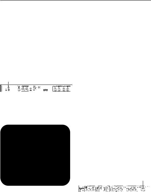
Turn the Program Select knob to choose a program. The display flashes the number of the program to be loaded. Press the knob to load the program.
P ram Select knob
Note that the
the MX200 comes with 99


 Factory programs and 99 User programs. A small dot appears at the bottom right of the Program Display window, indicating that the displayed program is a User program. For more information about editing programs, see page 10.
1

Quick Start
Audition the Effect
A tion Button
The Audition button allows you to preview the loaded program by playing short digital samples through the effect processors.
There are five audio samples included in the MX200, including various drum sounds, vocal, and guitar. In the factory setting, tap- ping the Audition button cycles through the five sounds, but you may want to repeat a particular sound as you choose or edit an effect. See page 11 for more information.
2

About the MX200
Overview
The MX200 is a dual-processor, single rack space multi-effects device designed with both live sound reinforcement and home recording in mind. Featuring the deep, rich reverb algorithms that built the Lexicon® legend, the MX200 offers increased versatility with dynamics and specialty effects—all instantly accessible via the extremely intuitive front panel.
Either way you use the MX200 – live or in the studio – you can choose two effects at once in one of four routing schemes: Dual Stereo (Parallel), Cascade (Serial), Mono Split or Dual Mono. The MX200 has 99 carefully crafted Factory programs, and 99 User programs that allow you to create your own custom effect settings. Front panel controls include Input Level, Mix 1 and Mix 2 controls, effects Routing button, independent Tempo and Bypass buttons, three Parameter knobs for each Processor, Program Select knob, an Audition button, and a Store button.
Studio Operation
The MX200 features a USB interface that lets it function as a “hardware plug-in” – recognized and functioning within a VSTTM
or Audio Units compatible recording application as a plug-in effect, but still operating as a dedicated hardware processor. This unique hardware plug-in feature lets you add legendary Lexicon effects to your com- puter-based recordings with full automation and recall features via an intuitive crossplatform plug-in window without overburdening your CPU.
Live Operation
Those using the MX200 in live applications will appreciate its intuitive front panel layout. The Active Reverb/Effects Matrix displays which two of the 32 available reverbs and effects are active, and all editing functions require only a single button push or turn of a knob. Dual independent processor control areas feature dedicated
Effects Select, Tempo, and Bypass buttons plus three Parameter knobs that provide instant access and control over the most critical parameters for the selected effect. Parameter change LEDs illuminate to indicate any changes to the 99 Factory or User programs. The Audition button plays one of five digitally recorded audio samples through the selected effects to audition their settings without the need for an external audio source.
3

Diagram - Front Panel
1 2 |
3 |
4 |
5 6 |
7 8 |
9 10 |
|
|
|
|
|
|
|
|
11 12 13 |
14 |
15 |
16 |
17 |
18 |
19 |
20 |
21 22 |
23 |
|
1. Dual Input Bargraph Meters |
|
|
7. Tempo Button - P2 |
|
||||||
LEDs indicate input level for each channel. |
|
Same as for Processor 1 (see #5). |
||||||||
2. Digital In LED |
|
|
8. Bypass Button - P2 |
|
||||||
Indicates when the S/PDIF digital input is |
|
Bypasses Processor 2. Red LED lights to |
||||||||
selected and active. |
|
|
indicate effect is bypassed. |
|
||||||
3. Routing Button |
|
|
9. Store Button |
|
|
|
||||
Press this button to cycle through the four |
|
Stores program modifications to one of the |
||||||||
signal routing options. For more informa- |
|
99 User program locations. Press the |
||||||||
tion about routing, see page 12. |
|
|
Store and Audition buttons simultaneous- |
|||||||
|
|
|
ly to access Utility functions. (See page 23 |
|||||||
4. Active Reverb / Effects Matrix |
|
|
for more information.) |
|
|
|||||
Indicates which effects are active at all |
|
|
10. Audition Button |
|
|
|||||
times. Green LED indicates active effect in |
|
|
|
|||||||
Processor 1, red LED indicates active |
|
|
Plays audio samples through the proces- |
|||||||
effect in Processor 2. |
|
|
sors to audition their settings. Press the |
|||||||
|
|
|
Audition and |
Store buttons simultaneous- |
||||||
5. Tempo Button - P1 |
|
|
ly to access the Utility functions. (See page |
|||||||
Tapping this button twice sets the Delay |
|
23 for more information.) |
|
|||||||
|
|
|
|
|
|
|
|
|
||
Time of Processor 1. LED flashes to indi- |
|
11. Input Knob |
|
|
|
|||||
cate current tempo, or lights solid when |
|
|
|
|
||||||
synched to MIDI. |
|
|
Controls the input level of both Left and |
|||||||
|
|
|
Right analog inputs. |
|
|
|||||
6. Bypass Button - P1 |
|
|
12. Mix 1 Knob |
|
|
|||||
Bypasses Processor 1. In the factory |
|
|
|
|
||||||
default, this puts the processor into Bypass |
Controls the P1 Wet/Dry effects mix. |
|||||||||
mode and allows dry, unprocessed signal |
|
|
|
|
|
|
|
|
|
|
to pass through to the outputs. To change |
|
13. Mix 2 Knob |
|
|
||||||
to Bypass Mute, which allows no signal |
|
|
Controls the P2 Wet/Dry effects mix. |
|||||||
(wet or dry) to pass, see Bypass Mode |
|
|
|
|
|
|
|
|
|
|
Select in the Utilities section on page 25. |
|
|
|
|
|
|
|
|
|
|
* Refer to the Effects Descriptions section for more information about parameters.
4
Diagram - Front Panel
14. Effect Select - P1
This button selects the reverb, delay, or effect to be loaded in Processor 1.
15. Pre Delay Knob - P1
Controls Pre Delay of the reverbs or the first parameter of the selected delay or effect in Processor 1.*
16. Decay Knob - P1
Controls Decay of the reverbs or the second parameter of the selected delay or effect in Processor 1.*
17. Variation - P1
Controls Liveliness or Diffusion (depending on the reverb selected) or the third parameter of the selected effect in Processor 1.*
18. Effect Select - P2
Same as for Processor 1 (see #14).
19. Pre Delay Knob - P2
Same as for Processor 1 (see #15).
20. Decay Knob - P2
Same as for Processor 1 (see #16).
21. Variation - P2
Same as for Processor 1 (see #17).
22. Program Display
2-character LED display indicates which of the 99 Factory or User programs is loaded. A small dot appears at the bottom right of the Program Display window, indicating that the displayed program is a User program. Also shows Utility settings and parameter values during editing.
23. Program Select Knob
Navigates through Factory and User programs, as well as Utility functions.
* Refer to the Effects Descriptions section for more information about parameters.
5
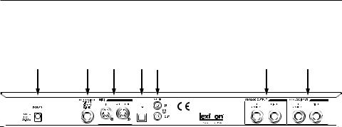
Diagram - Rear Panel
1 |
2 |
3 |
4 |
5 |
6 |
7 |
||
|
|
|
|
|
|
|
|
|
|
|
|
|
|
|
|
|
|
|
|
|
|
|
|
|
|
|
|
|
|
|
|
|
|
|
|
|
|
|
|
|
|
|
|
|
|
|
|
|
|
|
|
|
|
1. Power Jack
Connect only the included Harman Pro PS0913B power supply here.
2. Footswitch Input
An optional 2-button footswitch can be plugged into this TRS jack for independent Bypass control of P1 and P2. Use the Lexicon® LEX-DFS or a 2-button footswitch wired as follows:
Tip |
= Bypass 2 |
Ring |
= Bypass 1 |
Sleeve |
= Ground |
3. MIDI In, Out/Thru
Provides MIDI operation capabilities. Two 5-pin MIDI DIN connectors are available for MIDI IN and MIDI OUT/THRU. (See page 37 for MIDI Implementation chart.)
4. USB Port
Provides communication with a computer for use with MX-EditTM software and MX200 plug-in window using a standard USB cable. When the MX200 is connected to a computer via USB, briefly appears in the Program DisplayUSwindow.
5. S/PDIF Digital In/Out
Digital input accepts 44.1kHz / 48kHz signals. When the S/PDIF digital input is selected and active, the Digital In LED on the front panel lights.
6
Important: It is recommended that you do not connect any digital device to the MX200’s S/PDIF input that transmits at any other sample rate (such as 96kHz). Doing so can cause unpredictable performance. Make sure the device you are connecting to the MX200’s S/PDIF In is set as the Clock Master (if that option is available) and transmitting at a sample rate of 44.1kHz or 48kHz only. As with any other connection, if you need to unplug the S/PDIF cable, it is recommended that you switch to the analog inputs (see Digital Input Select in the Utility section) or bypass both processors before disconnecting the cable.
6. Balanced Analog Line Outputs
Left and Right RF-filtered 1/4” balanced/unbalanced TRS line outputs are servo-balanced, so no signal loss is incurred when using unbalanced connections. To use the Left output as a mono sum of both Left and Right signals, refer to the Stereo/Mono Output Mode Utility section on page 24.
7. Balanced Analog Line Inputs
Left and Right active analog 1/4” TRS balanced/unbalanced line inputs. If only a single plug is connected to the Left input, the signal is split and sent to both the Left and Right input paths.
Setup
Connecting the MX200
Parallel vs. Serial
The MX200 can be used as both a Parallel and Serial (in-line) effects processor. Typically, reverbs and delays are used in parallel, compressors and de-essers in serial, and modulated effects can be used in either configuration, depending on the desired application.
A Parallel Processor is connected by sending a copy of a signal (such as from an Aux Send of a mixer channel) to an effects device (such as the MX200), and the effected (or wet) signal is returned to the mixer or amp. It is then blended together with the original unaffected (dry) signal. This blend is called the Wet/Dry mix. This connection is most often used for reverbs, delays, and some modulated effects (such as chorus).
A Serial Processor is connected by sending the entire signal through the effects device and then to an amplifier or mixer, and is not blended with the unaffected (dry) signal. This is the type of connection most often used for a compressor, deesser, equalizer, and many modulated effects (such as tremolo, vibrato, and rotary).
The following illustrations show how to connect the MX200 in both Serial and Parallel configurations, using some common, real-world examples.
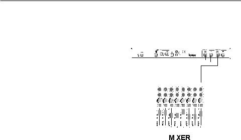
Parallel Connection
Mixer - Mono In/Stereo Out Setup
A |
A |
A |
Return 1 |
Return 2 |
Send 1 |
|
|
|
This setup is the most commonly used configuration in both live and studio applications.
1.Select routing 2 or 4 using the Routing button.
2.Connect the mixer’s Post Fader Aux Send output to the MX200’s Left (Mono) input.
3.Connect the MX200’s Left and Right outputs to a stereo Aux Return input on the mixer (or a stereo line input, or two adjacent line inputs if you like).
4.Set the gain on the mixer’s input channel appropriate to the source (vocal mic, guitar, keyboard, etc.).
5.Set the Aux Master level (if provided on your console) to the 12 o’clock position.
6.Set the Input on the MX200 to the 12 o’clock position.
7.Set the Mix 1 and Mix 2 knobs on the MX200 to their full clockwise (Wet) position.
8.Turn up the Aux Send level on the channel corresponding to the Postfader Aux Send (Aux 1 in this example) that the MX200 is connected to until the red Input Bargraph LEDs light only occasionally. If the red Input
7
Setup
Bargraph LEDs stay lit, too much signal is being sent to the MX200; reduce the Aux Master or Aux send on the mixer.
9. Turn up the Aux Return to the 12 o’clock position (or line input faders to the 0db positions, if you used that connection).
10. To increase or decrease the amount of effect on the signal, adjust the Aux Send level on the channel that you want affected.
Mixer - Dual Mono Setup
to 12 o’clock.
8. Turn up Aux Sends 1 and 2 on the mixer for the selected channels so the red Input Bargraph LEDs only light occasionally with signal (adjusting the Input knob on the MX200 may be necessary).
9. Control the amount of effect using the Aux Send levels on the selected mixer channels.
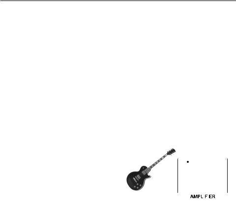
Serial Connections
Guitar - Effects Loop Setup
A |
A |
A |
A |
|
|
|
|
R rn 1 |
R rn 2 |
Send 1 |
Send 2 |
P |
r Amp P mp |
||
|
|
|
|
||||
|
|
|
|
In |
|
|
O |
|
|
|
|
|
|
|
|
|
|
|
|
|
|
|
|
|
|
|
|
|
|
|
|
|
|
|
|
|
|
|
|
This setup applies to a mixer with two (or more) Aux Sends and Returns. It utilizes the two effect sections in the MX200 as two separate effects with separate mono outputs, or a common stereo output.
1.Select routing 1 or 4 using the Routing button.
2.Connect Aux 1 send to the MX200 Left input.
3.Connect Aux 2 send to the MX200 Right input.
4.Connect the MX200 Left and Right outputs to the mixer’s Aux returns 1 and 2 for mono, or Stereo Aux L/R returns for stereo.
5.Set Mix 1 and Mix 2 knobs fully clockwise (Wet).
6.Set the MX200’s Input knob to the 12 o’clock position.
7.Set the Aux Return levels on the mixer
8
1.Select routing 2 using the Routing button (you can always experiment using other routings).
2.Connect guitar to the amp’s Input.
3.Connect the amp Effects Loop Send or Preamp Out to the MX200’s Left input.
4.Connect the MX200’s Left output to the amp’s Effects Loop Return or Power Amp In.
5.Set Mix 1 and Mix 2 knobs to the 12 o’clock position.
6.Adjust the Input level so the red Input Bargraph LEDs only light occasionally with signal.
7.To adjust the effect level, use the Mix 1 and Mix 2 knobs.

Setup
Instrument - In Line Setup |
Studio – Digital Setup |
||
|
|
|
|
|
|
|
S/PDIF Out |
|
|
|
|
|
|
|
S/PDIF In |
|
|
|
|
|
|
|
|
|
|
|
|
S eo
Line Input
This setup utilizes the MX200 as a multieffects processor connected in line from an instrument to a mixer. It is an ideal setup to use when your mixer does not have an Aux Send/Return option built in.
1.Select routing 2 using the Routing button (you can always experiment using other routings).
2.Connect a line level signal directly from your instrument to the MX200 Inputs. (use Left input for mono signals).
3.Connect the MX200’s Left and Right outputs to two separate mixer channels or a stereo line input.
4.Set the MX200’s Input knob to the 12 o’clock position.
5.Set Mix 1 and Mix 2 knobs to 12 o’clock position.
6.Adjust the Input level so the red Input Bargraph LEDs only light occasionally with signal.
7.Adjust the Mix 1 and Mix 2 knobs for the desired effect mix level.
This setup is ideal if you are using the MX200 as a hardware plug-in in a digital recording system. This setup requires that you are using an I/O device with S/PDIF In/Out, or a digital mixer with S/PDIF I/O option.
1.Select routing 2 using the Routing button. (You can always experiment with other routings.)
2.Connect the S/PDIF output on your soundcard, audio interface or mixer to the S/PDIF In on the MX200.
3.Connect the MX200 S/PDIF Out to the S/PDIF input on your soundcard, audio interface or mixer.
4.Make sure the device you are connecting to the MX200’s S/PDIF In is set as the Clock Master (if that option is available) and transmitting at a sample rate of 44.1kHz or 48kHz only. (Refer to the documentation for your device and/or software for proper setup.)
5.Once the MX200 is locked correctly with your device, the Digital In LED lights.
If the Digital In LED does not light, check your cables and make sure that your I/O device is set as Master Clock.
9
 Loading...