


User Guide 
20/20 AD
20 Bit A/D Converter

Lexicon
Precautions
The 20/20 AD is a rugged device with extensive electronic protection. However, you should observe the same reasonable precautions that apply to any piece of audio equipment:
•Always use the correct line voltage.
•Do not install the 20/20 AD in a closed, unventilated rack, or directly above heat-producing equipment such as power amplifiers.
•Never attach audio power amplifier outputs (speaker outputs) directly to any of the 20/20 AD's connectors.
•To prevent fire or shock hazard, do not expose the 20/20 AD to rain or moisture.
Notice
This equipment generates and uses radio frequency energy and if not installed and used properly, that is, in strict accordance with the manufacturer's instructions, may cause interference to radio and television reception. It has been type tested and found to comply with the limits for a Class A computing device in accordance with the specifications in Subpart J of Part 15 of FCC Rules, which are designated to provide reasonable protection against such interference in a residential installation. However, there is no guarantee that interference will not occur in a particular installation. If this equipment does cause interference to radio or television reception, which can be determined by turning the equipment OFF and ON, the user is encouraged to try to correct the interference by one or more of the following measures:
Reorient the receiving antenna
Relocate the computer with respect to the receiver Move the computer away from the receiver
Plug the computer into a different outlet so that the computer and receiver are on different branch circuits.
If necessary, the user should consult the dealer or an experienced radio/television technician for additional suggestions. The user may find the following booklet prepared by the Federal Communications Commission helpful:
"How to identify and Resolve Radio/TV Interference Problems."
This booklet is available from the U.S. Government Printing Office, Washington, DC 20402, Stock No. 004-000- 00345-4.
This triangle, which appears on |
|
|
|||||
your component, alerts you to |
|
|
|
||||
the presence of uninsulated, |
|
|
|
CAUTION |
|
||
dangerous voltage inside the |
|
|
|
||||
|
|
|
|||||
enclosure...voltage that may be |
|
RISK OF ELECTRIC SHOCK |
|
||||
sufficient to constitute a risk of |
|
|
|
|
|
DO NOT OPEN |
|
|
|
|
|
|
|
|
|
|
|
|
|
|
|
||
shock. |
|
|
|||||
Copyright © 1993 |
Lexicon Inc. |
|
3 Oak Park |
|
Bedford, MA 01730 USA |
|
Tel 781-280-0300 |
|
Fax 781-280-0499 |
All Rights Reserved |
|
This triangle, which appears on your component, alerts you to important operating and maintenance instructions in this accompanying literature.
This publication is protected by copyright and all rights are reserved. No part of it may be reproduced or transmitted by any means or in any form, without express prior consent in writing from Lexicon.
Lexicon Part # 070-09090 Rev 1 |
Printed in the United States of America |
|

20/20 AD User Guide
SAFETY SUMMARY
The following general safety precautions must be observed during all phases of operation, service and repair of this instrument. Failure to comply with these precautions, or with specific warnings elsewhere in these instructions violates safety standards of design manufacture and intended use of the instrument. Lexicon assumes no liability for the customer's failure to comply with these requirements.
GROUND THE INSTRUMENT
To minimize shock hazard the instrument chassis and cabinet must be connected to an electrical ground. The instrument is equipped with a three-conductor AC power cable. The power cable must either be plugged into an approved three-contact electrical outlet or used with a three-contact to two-contact adapter with the grounding wire (green) firmly connected to an electrical ground (safety ground) at the power outlet. The power jack and mating plug of the power cable meet International Electrotechnical Commission (IEC) safety standards.
DO NOT OPERATE IN AN EXPLOSIVE
ATMOSPHERE
Do not operate the instrument in the presence of flammable gases or fumes. Operation of any electrical instrument in such an environment constitutes a definite safety hazard.
KEEP AWAY FROM LIVE CIRCUITS
Operating personnel must not remove instrument covers. Component replacement and internal adjustments must be made by qualified maintenance personnel. Do not replace components with power cable connected. Under certain conditions, dangerous voltages may exist even with the power cable removed. To avoid injuries, always disconnect power and discharge circuits before touching them.
DO NOT SERVICE OR ADJUST ALONE
Do not attempt internal service or adjustment unless another person, capable of rendering first aid and resuscitation, is present.
DO NOT SUBSTITUTE PARTS OR MODIFY
INSTRUMENT
Because of the danger of introducing additional hazards, do not install substitute parts or perform any unauthorized modification to the instrument.
DANGEROUS PROCEDURE WARNINGS
Warnings, such as the example below, precede potentially dangerous procedures throughout this manual. Instructions contained in the warnings must be followed.
WARNING
Dangerous voltages, capable of causing death, are present in this instrument. Use extreme caution when handling, testing and adjusting.
SAFETY SYMBOLS
General definitions of safety symbols used on equipment or in manuals.
WARNING 

CAUTION
NOTE:
Instruction manual symbol: the product will be marked with this symbol when it is necessary for the user to refer to the instruction manual in order to protect against damage to the instrument.
Indicates dangerous voltage. (Terminals fed from the interior by voltage exceeding 1000 volts must be so marked.)
The WARNING sign denotes a hazard. It calls attention to a procedure, practice, condition or the like which, if not correctly performed or adhered to, could result in injury or death to personnel.
The CAUTION sign denotes a hazard. It calls attention to an operating procedure, practice, condition or the like which, if not correctly performed or adhered to, could result in damage to or destruction of part or all of the product.
The NOTE sign denotes important information. It calls attention to procedure, practice, condition or the like which is essential to highlight.
CAUTION
Electrostatic Discharge (ESD) Precautions
The following practices minimize possible damage to ICs resulting from electrostatic discharge or improper insertion.
•Keep parts in original containers until ready for use.
•Avoid having plastic, vinyl or styrofoam in the work area.
•. Wear an anti-static wrist-strap.
•Discharge personal static before handling devices.
•Remove and insert boards with care.
•When removing boards, handle only by non-conductive surfaces and never touch open-edge connectors except at a static-free workstation.*
•Minimize handling of ICs.
•. Handle each IC by its body.
•Do not slide ICs or boards over any surface.
•Insert ICs with the proper orientation, and watch for bent pins on ICs.
•Use anti-static containers for handling and transport.
*To make a plastic-laminated workbench anti-static, wash with a solution of Lux liquid detergent, and allow to dry without rinsing.

20/20 AD User Guide
Contents
Introduction |
|
Controls and Connectors ...................................................................... |
1 |
Unpacking • Power • Mounting .......................................................... |
1 |
Front Panel Controls .......................................................................... |
2 |
The Converter • The Level Meters • The Compressor |
|
Synchronization and Output Formatting • Alternate Modes |
|
Rear Panel Connectors ..................................................................... |
5 |
Audio Connections ............................................................................ |
6 |
Connectors • Cables |
|
Using the 20/20 AD ................................................................................. |
9 |
Analog Inputs ..................................................................................... |
9 |
Termination and Grounding via Internal Jumpers ............................. |
9 |
Balanced and Unbalanced Input Signals ......................................... |
12 |
Front Panel Adjustments ................................................................. |
13 |
Synchronization and Sample Rate .................................................. |
14 |
AES Sync • Word Clock • Internal and External Modes |
|
About Dither ..................................................................................... |
16 |
Psychoacoustically Optimized Noise Shaping (PONS) |
|
Automatic Offset Removal ............................................................... |
18 |
Compressor Modes ......................................................................... |
18 |
Dynamic Range Compression • Non-Linear Transfer |
|
Functions • Overload Protection • Digitizing Analog Tape |
|
Link • Display |
|
Digital Audio Outputs ....................................................................... |
23 |
Realigning Two DAT Recordings .................................................... |
24 |
Digital Sinewave Generator ............................................................. |
24 |
Specifications ....................................................................................... |
25 |
Definition of Terms .............................................................................. |
27 |

20/20 AD User Guide
Introduction
The 20/20 AD is an analog-to-digital converter which can be configured for two 20-bit channels, or four 18-bit channels. Twin on-board signal processors provide 20-bit to 16-bit compression in the digital domain, as well as DC removal and a choice of four dither types.
The compressor allows leeway in setting levels and provides insurance against clipping in the digital domain. In addition, it provides 195 soft compression curves and 13 time constants to allow for more creative functions, such as emulation of tape saturation or analog compression.
This manual provides some basic information on conversion, but assumes the user will be familiar with the principles of analog-to-digital conversion, as well as with the digital audio interface formats output by the 20/20 AD.
Information on specific data which may be required by any target device should be obtained from the manufacturer.
Lexicon has attempted to provide correct information and functional capability corresponding to digital audio standards known and available to us at the time of publication of this document and manufacture of this instrument. As standards evolve, Lexicon may make updates to documentation and/or system software available for purchase.
Lexicon's warranty on this product excludes consequential damages resulting from the use of this product. Local jurisdiction may extend the user additional rights.
AES/EBU Interface (Professional)
The AES/EBU interface conforms to both the AES3-1992 (ANSI S4.40-1992) specification and the EBU document, Tech 3250-E. Both inputs and outputs are balanced, transformer-coupled designs, with a female XLR input and a male XLR output, conforming to the standard convention of IEC 268, Part 12. Input and output levels comply with CCITT V.11. On this device, the professional form of the digital audio and auxiliary data has been labeled "AES" in accordance with general usage.
S/PDIF – Sony/Phillips Digital Interface Format (Consumer)
The S/PDIF interface conforms to the Channel Status Type II format, as specified in the EIAJ CP-340 Digtial Audio Interface Standard, dated September, 1987, and to IEC 958, First Edition 1989-03. As of November 20, 1991, amendments to IEC 958, which include specifications for the implementation of auxiliary data for the consumer format, were under review. Until new specifications are published, this device must conform to currently approved specifications. On this device, the consumer form of the digital audio and auxiliary data has been labeled "SPDIF" in accordance with general usage.
20/20 AD User Guide |
Controls and |
Controls and Connectors |
|
|
Connectors |
|
|
After unpacking the 20/20 AD, save all packing materials in case you ever need Unpacking to ship the unit. Thoroughly inspect the 20/20 AD and packing materials for signs
of damage. Report any shipment damage to the carrier at once. The following accessories are included with the 20/20 AD:
1. Power Cable
2. User Guide
3. Quick Reference Guide
The 20/20 AD is equipped with a 3-pin IEC connector and detachable line cord. Power Connect the cable end of the 20/20 AD line cord to the 20/20 AD power
connector. Then plug the line cord into an AC wall socket providing voltage corresponding to the data plate on the unit.
The 20/20 AD measures 19"W x 1.75"H x 13.9"D (483 x 45 x 353 mm). Make Mounting sure that the 20/20 AD is securely screwed into the rack, and that support is
provided for the rear of the chassis during transport to avoid possible damage from severe mechanical shock.
The maximum ambient operating temperature is 95° F (35° C). Provide adequate ventilation if the 20/20 AD is mounted in a closed rack with heat-producing equipment.
1
Controls and Connectors |
Lexicon |
|
20/20 AD
Front Panel
Controls
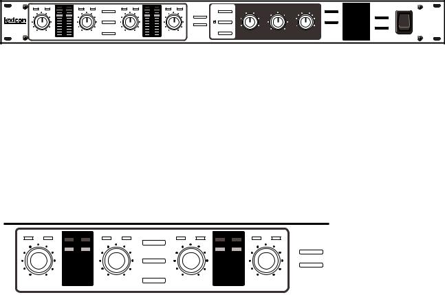
The 20/20 AD front panel controls are divided into three functional groups for conversion, compression, and synchronization/output formatting.
|
Synchronization and |
Converter |
Compressor Output Formatting |
|
|
UNBAL THRESH |
OVL |
|
0 |
|
3 |
|
6 |
|
12 |
|
18 |
|
24 |
|
30 |
|
36 |
|
42 |
1 |
60 |
|
UNBAL THRESH |
1dB |
SCALE |
UNBAL |
|
THRESH |
OVL |
|
|
|
|
|
0 |
|
||
ALT |
|
|
|
|
3 |
|
|
|
|
|
|
|
|
6 |
|
|
PK |
HOLD |
|
|
|
12 |
|
|
|
|
|
18 |
|
||
|
|
|
|
|
|
|
|
|
|
|
|
|
|
24 |
|
|
|
|
|
|
|
30 |
|
|
ATTEN |
|
|
M |
36 |
+ |
|
MUTE |
|
|
|
C |
42 |
• |
|
2 |
|
|
|
3 |
P |
60 |
– |
|
|
|
|
|
|
||
UNBAL THRESH |
DISPLAY |
|
|
DIGITAL COMP/LIMITER |
|
100 |
DITHER |
WIDE |
20BIT |
|
POWER |
||
4 CHAN |
RMT |
|
6 |
|
-18 |
-14 |
|
mS |
|
HF |
PL DN SAMPLE RATE |
|
|
|
4 |
8 |
|
|
|
||||||||
~ |
|
|
|
|
|
|
|
48 |
44.1 |
|
20/20 AD |
||
LINK |
|
|
-22 |
|
-10 |
|
|
FORMAT |
|
||||
EMPH |
|
2 |
|
10 |
|
10 |
|
|
1S |
AES |
SPDIF |
EXT SYNC |
|
|
|
|
|
-26 |
|
-6 |
|
|
|
20 BIT A/D CONVERTER |
|||
|
|
|
|
|
|
|
– ∞ |
WC |
AES |
||||
|
ON |
0 |
|
12 |
-36 |
0 |
0 + |
|
|
|
|||
|
M C |
|
PRES |
LOCK |
|
|
|||||||
|
VID |
|
P |
|
• |
AES / WC: |
|
|
|||||
4 |
|
|
GAIN |
THRESHOLD |
RELEASE |
|
|
|
|
||||
The Converter
Gain Controls: 1, 2, 3 and 4
Provide continuously variable gain control over a 30dB range.
Note: In 2-channel mode, only 1 and 2 are active.
UNBAL
Lights when there is a mismatch between the input signal and the setting of the rear-panel Balance switch.*
THRESH
When the compressor is on, indicates that the input level has risen above the selected compression threshold.
|
UNBAL THRESH |
|
OVL |
|
UNBAL |
|
|
THRESH |
1dB |
SCALE |
UNBAL |
|
|
THRESH |
|
OVL |
|
UNBAL THRESH |
|
|
|||||||||||||||
|
|
|
|
|
|
|
|
|
|
|
|||||||||||||||||||||||||
|
|
|
|
|
|
|
|
0 |
|
|
|
|
|
|
|
|
|
|
|
|
|
|
0 |
|
|
|
|
|
|
|
|
|
|
||
|
|
|
|
|
|
|
|
3 |
|
|
|
|
|
|
|
ALT |
|
|
|
|
|
|
|
|
3 |
|
|
|
|
|
|
~ |
4 CHAN |
||
|
|
|
|
|
|
|
|
|
|
|
|
|
|
|
|
|
|
|
|
|
|
|
|
|
|
|
|
|
|||||||
|
|
|
|
|
|
|
|
6 |
|
|
|
|
|
|
|
|
|
|
|
|
|
|
|
|
6 |
|
|
|
|
|
|
||||
|
|
|
|
|
|
|
|
|
|
|
|
|
|
|
|
|
|
|
|
|
|
|
|
|
|
|
|
|
|
||||||
|
|
|
|
|
|
|
|
12 |
|
|
|
|
|
|
|
PK |
HOLD |
|
|
|
|
|
12 |
|
|
|
|
|
|
EMPH |
|||||
|
|
|
|
|
|
|
|
|
|
|
|
|
|
|
|
|
|
|
|
|
|
|
|
|
|
||||||||||
|
|
|
|
|
|
|
|
18 |
|
|
|
|
|
|
|
|
|
|
|
|
18 |
|
|
|
|
|
|
||||||||
|
|
|
|
|
|
|
|
|
|
|
|
|
|
|
|
|
|
|
|
|
|
|
|
|
|
|
|
|
|
|
|
|
|
||
|
|
|
|
|
|
|
|
24 |
|
|
|
|
|
|
|
|
|
|
|
|
|
|
|
|
24 |
|
|
|
|
|
|
|
|
|
|
|
|
|
|
|
|
|
|
|
|
|
|
|
|
|
|
|
|
|
|
|
|
|
|
|
|
|
|
|
|
|
|
|
|
||
|
|
|
|
|
|
|
|
30 |
|
|
|
|
|
|
|
ATTEN |
|
|
|
|
|
30 |
|
|
|
|
|
|
|
|
|
|
|||
|
|
|
|
|
|
|
|
|
|
|
|
|
|
|
|
|
|
|
|
|
|
|
|
|
|
|
|
|
|
||||||
|
|
|
|
|
|
|
|
36 |
|
|
|
|
|
|
|
|
|
|
M |
|
36 |
|
+ |
|
|
|
|
|
|
|
|
||||
|
|
|
|
|
|
|
|
|
|
|
|
|
|
|
|
|
|
|
|
|
|
|
|
|
|
|
|
||||||||
|
|
|
|
|
|
|
|
|
|
|
|
|
|
|
|
|
|
|
|
|
|
|
|
|
|
|
|
||||||||
|
|
|
|
|
|
|
|
42 |
|
|
|
|
|
|
|
|
|
|
C |
|
42 |
|
• |
|
|
|
|
|
|
|
|||||
1 |
|
|
|
|
|
|
|
|
2 |
MUTE |
|
|
|
3 |
|
|
|
|
4 |
|
|
|
|
|
|||||||||||
|
|
|
|
|
|
|
|
|
|
|
|
|
|
|
|
|
|
|
|
||||||||||||||||
|
|
|
|
60 |
|
|
|
|
|
|
|
|
|
P |
|
60 |
|
– |
|
|
|
|
|
||||||||||||
|
|
|
|
|
|
|
|
|
|
|
|
|
|
|
|
|
|
|
|
|
|
||||||||||||||
|
|
|
|
|
|
|
|
|
|
|
|
|
|
|
|
|
|
|
|
|
|
|
|
|
|
|
|||||||||
|
|
|
|
|
|
|
|
|
|
|
|
|
|
|
|
|
|
|
|
|
|
|
|
|
|
|
|
|
|
|
|
|
|
|
|
1dB SCALE |
|
|
|
|
|
|
PK HOLD |
|
|
|
|
|
|
|
|
ATTEN |
|
|
|
|
|
|
|
||||||||||||
Press to select 1dB Scale |
Press to cause the level |
Press to attenuate balanced |
|||||||||||||||||||||||||||||||||
display on level meters. |
|
|
|
meter LEDs to hold at the |
input signals |
by 6dB. Press |
|||||||||||||||||||||||||||||
Also used to select alternate |
highest level received. Press |
again to turn attenuation off. |
|||||||||||||||||||||||||||||||||
again to deactivate. |
|
|
|
|
|
Do |
not use |
this control on |
|||||||||||||||||||||||||||
modes. |
|
|
|
|
|
|
|
|
|
|
|
||||||||||||||||||||||||
|
|
|
|
|
|
|
|
|
|
|
|
|
|
|
|
|
|
|
|
|
|
|
|
|
|
|
|
|
|||||||
unbalanced signals.
4 CHAN
Push on-push off selection of 2-channel or 4-channel mode; lit when in 4-channel mode.
EMPH
Turns pre-emphasis on and off.
* Non-linearity of the potentiometer can cause the signal to become unbalanced when the level knob is set to 11:30. To correct this, turn the knob slightly in either direction until the UNBAL light goes out.
2

20/20 AD User Guide |
Controls and Connectors |
The Level Meters
When the compressor is off, the behavior of the level meters is determined by the settings of the 1dB SCALE, and PK HOLD switches.
When the compressor is on, pressing DISPLAY will cause gain reduction (in dB) to be displayed on the two right hand meters (2-channel mode) or on all four meters (4-channel mode).
The following charts show all of the possible states of the level meter and the value in decibels for each state.
|
Switches ON |
Meters 1 & 2 |
Meters 3 & 4 |
|
|
|
|
|
|
NORMAL |
1dB SCALE |
GAIN |
|
|
|
|
|
|
|
|
|
|
|
|
REDUCTION |
4-Channel |
none |
Normal |
Normal |
|
|
|
OVL |
|
- red - |
OVL |
OVL |
1 |
|
|
|
|
|
|
0 |
|
- red - |
0 |
0 |
2 |
|
1 dB SCALE |
1 dB Scale |
1 dB Scale |
|
|
|
|
||||||
|
|
|
|
|||||||||
Mode |
|
|
|
|
||||||||
DISPLAY |
Gain Reduction |
Gain Reduction |
|
|
|
3 |
|
- yellow - |
-3 |
-1 |
3 |
|
|
|
|
|
6 |
|
- yellow - |
-6 |
-2 |
4 |
|||
|
|
|
|
|
|
|
|
|||||
2-Channel |
none |
Normal |
(Blank) |
|
|
|
12 |
|
- green - |
-12 |
-3 |
5 |
|
|
|
|
|||||||||
1 dB SCALE |
Normal |
1 dB Scale |
|
|
|
18 |
|
- green - |
-18 |
-4 |
6 |
|
Mode |
|
|
|
|
||||||||
|
|
|
|
|||||||||
DISPLAY |
Normal |
Gain Reduction |
|
|
|
24 |
|
- green - |
-24 |
-5 |
7 |
|
|
|
|
|
|
||||||||
|
|
|
|
30 |
|
- green - |
-30 |
-6 |
8 |
|||
|
|
|
|
|
|
|
|
|||||
|
|
|
|
|||||||||
|
|
|
|
|
|
|
36 |
|
- green - |
-36 |
-7 |
9 |
|
|
|
|
|
|
|
|
|||||
|
|
|
|
|
|
|
42 |
|
- green - |
-42 |
-8 |
10 |
|
|
|
|
|
|
|
|
|||||
|
|
|
|
|
|
|
60 |
|
- green - |
-60 |
-9 |
11 |
|
|
|
|
|
|
|
|
|||||
|
|
|
|
|
|
|
|
|
|
|
|
|
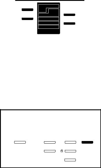
The Compressor
DISPLAY
Press to cause gain reduction to be displayed on the level meters — In 2-channel mode, only the right two level meters are activated; in 4- channel mode, all four level meters display compression. Press again to deactivate.
LINK
In 2-channel mode, links the left and right compressors ; in 4-channel mode, where 1,2 and 3,4 are already linked, this control links the two pairs.
ON
Turns the compressor on and off.
|
|
|
DISPLAY |
|
|
|
|
DIGITAL COMP/LIMITER |
|
100 |
|||||
|
RMT |
|
|
6 |
|
|
|
|
|
||||||
|
4 |
|
8 |
-18 |
-14 |
|
mS |
||||||||
|
|
|
|
|
|
|
|
||||||||
|
|
|
|
|
|
|
-22 |
|
-10 |
|
|
|
|
||
|
|
|
LINK |
2 |
|
|
|
10 |
|
|
|
|
1S |
||
|
|
|
|
|
|
|
|
|
|
||||||
|
|
|
|
|
|
|
|
|
10 |
|
|
|
|||
|
|
|
|
|
|
|
|
|
|
|
|||||
|
|
|
|
|
|
|
|
|
-26 |
-6 |
|
|
|
∞ |
|
|
|
|
ON |
0 |
|
|
|
12 |
-36 |
0 |
0 |
|
|
||
|
|
|
|
M |
C |
P |
+ |
|
• – |
||||||
|
VID |
|
|
|
|
|
|
|
|||||||
|
|
|
|
|
GAIN |
THRESHOLD |
RELEASE |
||||||||
|
|
|
|
|
|
|
|
|
|
|
|
|
|
|
|
GAIN |
|
|
|
|
|
THRESHOLD |
|
|
|
|
|||||
Adjusts the gain of low level |
Sets the level at which com- |
||||||||||||||
signals (below the compres- |
pression starts. |
|
|
|
|||||||||||
sion threshold) between the |
|
|
|
|
|
|
|
||||||||
converter and the compres- |
|
|
|
|
|
|
|
||||||||
sor. |
|
|
|
|
|
|
|
|
|
|
|
|
|||
RELEASE
This control allows adjustment of the release time of the compressor. Release times from 0mS to ∞ are available. The attack time of the compressor is automatically set as a function of the signal rise time.
3
Controls and Connectors |
Lexicon |
|
Synchronization
and
Output Formatting
DITHER
Selects the type of dither: wide bandwidth, 20 bit, or High Frequency .
FORMAT
Selects the format to be available at the output connectors, AES or S/PDIF.
Note: The format selected here will be sent to all outputs.
DITHER |
WIDE |
20 BIT |
|
|
HF |
PL DN |
SAMPLE RATE |
|
48 |
44.1 |
|
FORMAT |
|
||
|
AES |
SPDIF |
EXT SYNC |
|
WC |
AES |
|
|
|
||
AES / WC: |
PRES |
LOCK |
|
|
|
|
|
AES/WC
In internal sync mode, PRES indicates that either WC or AES is available at the inputs as a sync source.
In external sync mode, PRES indicates that the selected sync source is present at the input connectors.
LOCK lights in external sync mode to indicate the unit has successfully locked to the incoming signal (WC or AES).
SAMPLE RATE
Selects the sample rate of the A/D conversion. This switch should be set to the same sample rate as your sync source. When Word Clock is selected as an external sync source, the AES Channel Status Sample Rate bit will be set to the sample rate value you have selected here.
(The PL DN setting of this switch is reserved for future enhancements.)
EXT SYNC
This switch allows selection of: Internal mode (unlit), Word Clock source, or AES source.
Alternate Modes
To activate
the alternate modes...
press and hold |
...then press one of these. |
|||
|
|
|||
1dB SCALE |
ATTEN |
|
|
DISPLAY DITHER |
ALT |
MUTE |
RMT |
||
|
~ 4 CHAN |
|
|
LINK |
|
|
|
ON |
|
|
|
|
||
|
|
|
|
|
Repeat to exit the alternate mode. VID
ALT - ATTEN
Mutes the outputs. Note that the level meters still work. To unmute, hold ALT and press ATTEN again.
ALT - 4 CHAN
Activates output of a digital sinewave at the AES ports.
ALT - DISPLAY
Activates remote mode/front panel lockout. When activated, the 1dB SCALE and DISPLAY LEDs flash and front panel controls are locked into their current settings. To unlock, hold ALT and press DISPLAY again.
ALT - LINK
Only active in 4-channel mode. Activates a short tone burst. See Realigning Two DAT Recordings.
ALT - ON
Reserved for future enhancements.
ALT - DITHER
Activates psychoacoustically optimized noise shaping. When activated, WIDE, 20BIT and HF will be lighted.
Note that this type of dither can only be used in 2-chan- nel mode; activating will disable 4-channel mode and compressor functions.
4
 Loading...