


PCM 91
Digital Reverberator |
User Guide |
 A Harman International Company
UNPACKING AND INSPECTION
After unpacking the PCM 91, save all packing materials in case you ever need to ship the unit. Thoroughly inspect the PCM 91 and packing materials for signs of damage. Report any shipment damage to the carrier at once; report equipment malfunction to your dealer.
PRECAUTIONS
Save these instructions for later use.
Follow all instructions and warnings marked on the unit.
Always use with the correct line voltage. Refer to the manufacturer's operating instructions for power requirements. Be advised that different operating voltages may require the use of a different line cord and/or attachment plug.
Do not install the unit in an unventilated rack, or directly above heat producing equipment such as power amplifiers. Observe the maximum ambient operating temperature listed in the product specification.
Slots and openings on the case are provided for ventilation; to ensure reliable operation and prevent it from overheating, these openings must not be blocked or covered. Never push objects of any kind through any of the ventilation slots. Never spill a liquid of any kind on the unit.
This product is equipped with a 3-wire grounding type plug. This is a safety feature and should not be defeated.
Never attach audio power amplifier outputs directly to any of the unit's connectors.
To prevent shock or fire hazard, do not expose the unit to rain or moisture, or operate it where it will be exposed to water.
Do not attempt to operate the unit if it has been dropped, damaged, exposed to liquids, or if it exhibits a distinct change in performance indicating the need for service.
This unit should only be opened by qualified service personnel. Removing covers will expose you to hazardous voltages.
This triangle, which appears on your component, |
This triangle, which appears on your component, |
|
alerts you to the presence of uninsulated,CAUTION |
alerts you to important operating and |
|
dangerous voltage inside the |
- |
maintenance instructions in this |
voltage that may be sufficient to |
RISK OF ELECTRIC SHOCK |
accompanying literature. |
constitute a risk of |
DO NOT OPEN |
|

NOTICE
This equipment generates and uses radio frequency energy and if not installed and used properly, that is, in strict accordance with the manufacturer's instructions, may cause interference to radio and television reception. It has been type tested and found to comply with the limits for a Class B computing device in accordance with the specifications in Part 15 of FCC Rules, which are designated to provide reasonable protection against such interference in a residential installation. However, there is no guarantee that interference will not occur in a particular installation. If this equipment does cause interference to radio or television reception, which can be determined by turning the equipment OFF and ON, the user is encouraged to try to correct the interference by one or more of the following measures:
Reorient the receiving antenna
Relocate the computer with respect to the receiver
Move the computer away from the receiver
Plug the computer into a different outlet so that the computer and receiver are on different branch circuits.
If necessary, the user should consult the dealer or an experienced radio/television technician for additional suggestions. The user may find the following booklet prepared by the Federal Communications Commission helpful:
"How to identify and Resolve Radio/TV Interference Problems."
This booklet is available from the U.S. Government Printing Office, Washington, DC 20402, Stock No. 004-000-00345-4.
Le présent appareil numérique n'émet pas de bruits radioélectriques dépassant les limites applicables aux appareils numériques de la class B prescrites dans le Règlement sur le brouillage radioélectrique édicté par le ministère des Communications du Canada.
 A Harman International Company
Lexicon, Inc.
3 Oak Park
Bedford, MA 01730-1441 USA Tel 781-280-0300
Fax 781-280-0490 www.lexicon.com
Customer Support
Tel 781-280-0300
Fax 781-280-0495 (Sales)
Fax 781-280-0499 (Service)
Lexicon Part No. 070-12662 | Rev 1 | 09/01
© 2001 Lexicon, Inc. All rights reserved.
This document should not be construed as a commitment on the part of Lexicon, Inc. The information it contains is subject to change without notice. Lexicon, Inc. assumes no responsibility for errors that may appear within this document.

Introduction
Lexicon
Introduction |
|
|
DK |
Vigtig information om sikkerhed ..................................... |
iv |
FI |
Tärkeitä turvallisuusohjeita............................................... |
iv |
NO |
Viktig informasjon om sikkerhet ....................................... |
v |
SE |
Viktiga säkerhetsföreskrifter .............................................. |
v |
DE |
Wichtige Sicherheitsanweisungen.................................... |
vi |
ES |
Instrucciones importantes de seguridad .......................... |
vi |
FR |
Instructions de Sûreté Importantes ................................. |
vii |
IT |
Importanti norme di sicurezza ........................................ |
vii |
Section 1: Getting Started |
|
|
About the PCM 91 .................................................................... |
1-2 |
|
The Presets • Program Sorting • Soft Control • The Algorithms • |
|
|
Tempo Control • Editing • User Interface |
|
|
Front Panel Overview ................................................................ |
1-4 |
|
Rear Panel Overview.................................................................. |
1-6 |
|
Block Diagram........................................................................... |
1-8 |
|
Installation Notes ...................................................................... |
1-9 |
|
Mounting • Power Requirements • Audio Connections • |
|
|
Control Connections • Connectors • Setting Audio Levels • |
|
|
Configurations • Memory Cards |
|
|
Section 2: Basic Operation |
|
|
Modes of Operation.................................................................. |
2-2 |
|
Navigating a Matrix • Go or Pro • Info • History of Effects |
|
|
Loaded |
|
|
Control Mode ........................................................................... |
2-5 |
|
Row 0 Audio • Row 1 System • Row 2 Card • Row 3 MIDI • |
|
|
Row 4 Setup • Row 5 Mapx • Row 6 Chain |
|
|
Section 2: Basic Operation (continued) |
|
Program and Register Banks.................................................... |
2-17 |
Selecting Effects • Bank and Row Labels • Sorting Effects |
|
Tempo Mode .......................................................................... |
2-20 |
The Tempo Mode Matrix • Row 0 Tempo • Row 1 Tap |
|
Editing an Effect ...................................................................... |
2-22 |
The Soft Knob • The Soft Row • Compare • Bypass • Store |
|
Operations • The Full Edit Matrix • Patching • The Custom |
|
Row |
|
Section 3: Algorithms and Parameters |
|
About the Algorithms................................................................ |
3-2 |
Random Hall • Ambience • Rich Plate • Concert Hall • |
|
Chamber/Room |
|
The Dual Reverb Algorithms...................................................... |
3-9 |
The Reverb Blocks • Dual Mono Reverbs • Cascade Reverbs |
|
The Parameters ....................................................................... |
3-21 |
Compress • Controls • Custom • Delay • Design • Echo • |
|
Expand • Modulation • Patches • Reflect • Spatial EQ • Time |
|
Section 4: Presets |
|
Overview................................................................................... |
4-2 |
Program Bank 0: Halls ............................................................... |
4-3 |
Orchestral • Vocal • Live Sound • |
Instrument • Custom |
Program Bank 1: Rooms ............................................................ |
4-8 |
Instrument • Vocal • Live Sound • |
Drums&Perc • Custom |
Program Bank 2: Plates............................................................ |
4-14 |
Instrument • Vocal • Live Sound • |
Drums&Perc • Custom |
Program Bank 3: Post.............................................................. |
4-19 |
Indoor Small • Indoor Large • Outdoor • Spatial • Custom
ii

PCM 91
Introduction
Section 4: Presets (continued) |
|
|
Section 6: Troubleshooting |
|
|
Program Bank 4: Splits ............................................................ |
4-25 |
Low Voltage .............................................................................. |
6-2 |
||
Mono • Stereo • Live Sound • |
Instrument • Custom |
|
Overheating |
6-2 |
|
|
|
|
|||
Program Bank 5: Studio .......................................................... |
4-31 |
Common MIDI Problems |
6-2 |
||
Environments • Instruments • |
Vocal • Drums/Perc • Custom |
|
|||
|
Operational Problems |
6-2 |
|||
Program Bank 6: Live |
4-37 |
||||
No Digital Audio Output • No Effects Output |
|
||||
Acoustic • Electric • Vocal • Drums/Perc • Custom |
|
|
|||
|
Power On Behavior |
6-3 |
|||
Program Bank 7: Post |
4-43 |
||||
Restoring Factory Default Settings |
6-3 |
||||
Small Spaces • Medium Spaces • Large Spaces • Cool Places • |
|
||||
|
Reinitialization |
6-4 |
|||
Custom |
|
|
|||
Program Bank 8: Surround ...................................................... |
4-48 |
|
|
||
Small Spaces • Large Spaces • Unnatural FX • Custom • |
|
Appendix |
|
||
“Clean Slate” Presets |
|
|
Specifications |
A-2 |
|
|
|
|
|||
Section 5: MIDI Operation |
|
|
Declaration of Conformity......................................................... |
A-4 |
|
|
|
|
|
||
Selecting a MIDI Channel.......................................................... |
|
5-2 |
|
|
|
Accessing Programs and Registers |
............................................. |
5-2 |
|
|
|
Controlling Tempo Rate with MIDI Clock .................................. |
5-3 |
|
|
||
MIDI Tempo Control • Using the PCM 91 as a MIDI Clock |
|
|
|
||
Source • Slaving Two or More PCM 91s |
|
|
|
||
Controller Quirks....................................................................... |
|
5-4 |
|
|
|
The ADJUST Knob, Custom Controls, Foot Pedal, Foot SW1, and |
|
|
|||
Foot SW 2 as MIDI Controllers .................................................. |
|
5-4 |
|
|
|
Controlling the Soft Knob with MIDI • Controlling the Soft |
|
|
|
||
Knob with a Foot Pedal |
|
|
|
|
|
Program Change Messages ....................................................... |
|
5-5 |
|
|
|
Automation ............................................................................... |
|
5-6 |
|
|
|
SysEx Automation • Controller Automation • Reset All |
|
|
|
||
Controllers • MIDI Clock and Clock Commands • PCM 90 |
|
|
|
||
Compatibility • Dynamic MIDI |
|
|
|
|
|
Bulk Data Dumps ...................................................................... |
|
5-8 |
|
|
|
MIDI Implementation Chart ...................................................... |
|
5-8 |
|
|
|
iii
Introduction
Lexicon
DK |
DANSK |
DK |
|
VIGTIG INFORMATION OM SIKKERHED
Gem denne vejledning til senere brug.
Følg alle anvisninger og advarsler på apparatet.
Apparatet skal altid tilsluttes den korrekte spænding. Der henvises til brugsanvisningen, der indeholder specifikationer for strømforsyning. Der gøres opmærksom på, at ved varierende driftsspændinger kan det blive nødvendigt at bruge andre ledningsog/eller stiktyper.
Apparatet må ikke monteres i et kabinet uden ventilation eller lige over andet udstyr, der udvikler varme, f.eks. forstærkere. Den maksimale omgivelsestemperatur ved drift, der står opført i specifikationerne, skal overholdes.
Der er ventilationsåbninger i kabinettet. For at sikre apparatets drift og hindre overophedning må disse åbninger ikke blokeres eller tildækkes. Stik aldrig noget ind igennem ventilationsåbningerne, og pas på aldrig at spilde nogen form for væske på apparatet.
Dette apparat er forsynet med et stik med jordforbindelse. Denne sikkerhedsforanstaltning må aldrig omgås.
Udgangsstik fra audioforstærkere må aldrig sættes direkte i apparatet.
Apparatet må ikke udsættes for regn eller fugt og må ikke bruges i nærheden af vand for at undgå risiko for elektrisk stød og brand.
Apparatet må aldrig bruges, hvis det er blevet stødt, beskadiget eller vådt, eller hvis ændringer i ydelsen tyder på, at det trænger til eftersyn.
Dette apparat må kun åbnes af fagfolk. Hvis dækslet tages af, udsættes man for livsfarlig højspænding.
Denne mærkat på komponenten advarer om uisoleret, farlig spænding i apparatet ... høj nok til at give elektrisk stød.
Denne mærkat på komponenten advarer om vigtig driftsog vedligeholdsinformation i den tilhørende litteratur.
FI |
SUOMI |
FI |
|
||
|
TÄRKEITÄ TURVALLISUUSOHJEITA |
|
Säilytä nämä ohjeet tulevaa käyttöä varten.
Seuraa kaikkia yksikköön merkittyjä ohjeita ja varoituksia.
Käytä aina oikeaa verkkojännitettä. Tehovaatimukset selviävät valmistajan käyttöohjeista. Huomaa, että eri käyttöjännitteet saattavat vaatia toisenlaisen verkkojohdon ja/tai -pistokkeen käytön.
Älä asenna yksikköä telineeseen jossa ei ole tuuletusta, tai välittömästi lämpöä tuottavien laitteiden, esim. tehovahvistimien, yläpuolelle. Ympäristön lämpötila käytössä ei saa ylittää tuotespesifikaation maksimilämpötilaa.
Kotelo on varustettu tuuletusreiillä ja -aukoilla. Luotettavan toiminnan varmistamiseksi ja ylilämpenemisen välttämiseksi näitä aukkoja ei saa sulkea tai peittää. Mitään esineitä ei saa työntää tuuletusaukkoihin. Mitään nesteitä ei saa kaataa yksikköön.
Tuote on varustettu 3-johtimisella maadoitetulla verkkopistokkeella. Tämä on turvallisuustoiminne eikä sitä saa poistaa.
Älä kytke audiotehovahvistimen lähtöjä suoraan mihinkään yksikön liittimeen.
Sähköiskun ja palovaaran välttämiseksi yksikkö ei saa olla sateessa tai kosteassa, eikä sitä saa käyttää märässä ympäristössä.
Älä käytä yksikköä jos se on pudonnut, vaurioitunut, kostunut, tai jos sen suorituskyky on huomattavasti muuttunut, mikä vaatii huoltoa.
Yksikön saa avata vain laitteeseen perehtynyt huoltohenkilö. Kansien poisto altistaa sinut vaarallisille jännitteille.
Tämä kolmio, joka esiintyy komponentissasi, varoittaa sinua eristämättömän vaarallisen jännitteen esiintymisestä yksikön sisällä. Tämä jännite saattaa olla riittävän korkea aiheuttamaan sähköiskuvaaran.
Tämä kolmio, joka esiintyy komponentissasi, kertoo sinulle, että tässä tuotedokumentoinnissa esiintyy tärkeitä käyttöja ylläpito-ohjeita.
iv
PCM 91
Introduction
NO |
NORSK |
NO |
|
VIKTIG INFORMASJON OM SIKKERHET
Ta vare på denne veiledningen for senere bruk.
Følg alle anvisningene og advarslene som er angitt på apparatet.
Apparatet skal alltid anvendes med korrekt spenning. Produktbeskrivelsen inneholder spesifikasjoner for strømkrav. Vær oppmerksom på at det ved ulike driftsspenninger kan være nødvendig å bruke en annen ledningog/eller støpseltype.
Apparatet skal ikke monteres i skap uten ventilasjon, eller direkte over varmeproduserende utstyr, som for eksempel kraftforsterkere. Den maksimale romtemperaturen som står oppgitt i produktbeskrivelsen, skal overholdes.
Apparatet er utstyrt med ventilasjonsåpninger. For at apparatet skal være pålitelig i bruk og ikke overopphetes, må disse åpningene ikke blokkeres eller tildekkes. Stikk aldri noe inn i ventilasjonsåpningene, og pass på at det aldri søles noen form for væske på apparatet.
Dette apparatet er utstyrt med et jordet støpsel. Dette er en sikkerhetsforanstaltning som ikke må forandres.
Utgangsplugger fra audioforsterkere skal aldri koples direkte til apparatet.
Unngå brannfare og elektrisk støt ved å sørge for at apparatet ikke utsettes for regn eller fuktighet og ikke anvendes i nærheten av vann.
Apparatet skal ikke brukes hvis det har blitt utsatt for støt, er skadet eller blitt vått, eller hvis endringer i ytelsen tyder på at det trenger service.
Dette apparatet skal kun åpnes av fagfolk. Hvis dekselet fjernes, utsettes man for livsfarlig høyspenning.
Komponenten er merket med denne trekanten, som er en advarsel om at det finnes uisolert, farlig spenning inne i kabinettet ... høy nok til å utgjøre en fare for elektrisk støt.
Komponenten er merket med denne trekanten, som betyr at den tilhørende litteraturen inneholder viktige opplysninger om drift og vedlikehold.
SE |
SVENSKA |
SE |
|
VIKTIGA SÄKERHETSFÖRESKRIFTER
Spara dessa föreskrifter för framtida bruk.
Följ alla anvisningar och varningar som anges på enheten.
Använd alltid rätt nätspänning. Se tillverkarens bruksanvisningar för information om effektkrav. Märkväl, att andra matningsspänningar eventuellt kräver att en annan typs nätsladd och/eller kontakt används.
Installera inte enheten i ett oventilerat stativ, eller direkt ovanför utrustningar som avger värme, t ex effektförstärkare. Se till att omgivningens temperatur vid drift inte överskrider det angivna värdet i produktspecifikationen.
Behållaren är försedd med hål och öppningar för ventilering. För att garantera tillförlitlig funktion och förhindra överhettning får dessa öppningar inte blockeras eller täckas. Inga föremål får skuffas in genom ventilationshålen. Inga vätskor får spillas på enheten.
Produkten är försedd med en jordad 3-trådskontakt. Detta är en säkerhetsfunktion som inte får tas ur bruk.
Anslut aldrig audioeffektförstärkarutgångar direkt till någon av enhetens kontakter.
För att undvika elstöt eller brandfara får enheten inte utsättas för regn eller fukt, eller användas på ställen där den blir våt.
Använd inte enheten om den har fallit i golvet, skadats, blivit våt, eller om dess prestanda förändrats märkbart, vilket kräver service.
Enheten får öppnas endast av behörig servicepersonal. Farliga spänningar blir tillgängliga när locken tas bort.
Denna triangel, som visas på din komponent, varnar dig om en oisolerad farlig spänning inne i enheten. Denna spänning är eventuellt så hög att fara för elstöt föreligger.
Denna triangel, som visas på din komponent, anger att viktiga bruksanvisningar och serviceanvisningar ingår i dokumentationen i fråga.
v
Introduction
Lexicon
DE |
DEUTSCH |
DE |
|
WICHTIGE SICHERHEITSANWEISUNGEN
Heben Sie sich diese Sicherheitsanweisungen auch für später auf.
Befolgen Sie alle auf der Vorrichtung stehenden Anweisungen und Warnungen.
Immer nur mit der richtigen Spannung verwenden! Die ebrauchsanweisungen des Herstellers informieren Sie über die elektrischen Anforderungen. Vergessen Sie nicht daß bei verschiedenen Betriebsspannungen ggf. auch verschiedene Leitungskabel und/oder Verbindungsstecker zu verwenden sind.
Stellen Sie die Vorrichtung nicht in ein unbelüftetes Gestell oder unmittelbar über wärmeerzeugende Geräte wie z.B. Tonverstärker. Halten Sie die in den Produktspezifikationen angegebene maximale Umgebungstemperatur bei Betrieb ein.
Schlitze und Öffnungen im Gehäuse dienen der Belüfung; um verläßlichen Betrieb sicherzustellen und Überheizen zu vermeiden dürfen diese Öffnungen nich verstopft oder abgedeckt werden. Stecken Sie nie irgend einen Gegenstand durch die Belüftungsschlitze. Vergießen Sie keine Flüssigkeiten auf den Apparat.
Dieses Produkt is mit einem 3-drahtigen Erdungsstecker ausgerüstet. Diese Sicherheitsmaßnahme darf nicht unwirksam gemacht werden.
Schließen Sie nie Tonverstärker unmittelbar an einen Anschluß des Apparates an.
Um elektrischen Schlag oder Feuer zu vermeiden, setzen Sie den Apparat weder Regen noch Feuchtigkeit aus und betreiben Sie ihn nicht dort wo Wasser eindringen könnte.
Versuchen Sie nicht den Apparat zu betreiben falls er fallen gelassen, beschädigt, oder Flüssigkeiten ausgesetzt wurde, oder falls sich seine Arbeitsweise derart ändert daß daraus ein Bedarf nach Raparatur zu schließen ist.
Dieser Apparat sollte nur von qualifizierten Fachleuten geöffnet werden. Das Abnehmen von Abdeckungen setzt Sie gefährlichen Spannungen aus.
Dieses Dreieck auf Ihrem Apparat warnt Sie vor nicht-isolierter, gefährlicher Spannung im Gehäuse ... stark genug um eine Berührungsgefahr darzustellen.
Dieses Dreieck auf Ihrem Apparat bedeutet daß wichtige Betriebsund Wartungsanweisungen in der mitgelieferten Dokumentation zu finden sind.
ES |
ESPAÑOL |
ES |
|
INSTRUCCIONES IMPORTANTES
DE SEGURIDAD
Guarde esta instrucciones para uso posterior.
Utilice siempre el voltaje correcto. Diríjase a las instrucciones de operación del fabricante para obtener las especificaciones de potencia. Esté al tanto de que voltajes de operación distintos requieren el uso de cables y/o enchufes distintos.
No instale esta unidad en un estante sin ventilación, ni tampoco directamente encima de equipos que generen calor tales como amplificadores de potencia. Fíjese en las temperaturas ambientales máximas de operación que se mencionan en las especificaciones del producto.
Las aperturas y ranuras del chasis sirven para proveer la ventilación necesaria para operar la unidad con seguridad y para prevenir sobrecalentamiento, y por lo tanto no pueden ser obstruidas o cubiertas. No introduzca objetos de ningún tipo a través de las ranuras de ventilación, y nunca deje caer ningún líquido sobre la unidad.
Este producto está equipado con un enchufe de 3 clavijas con conexión a tierra. Éste es un elemento de seguridad que no debe ser eliminado.
Nunca conecte ningún tipo de salida de amplificadores de sonido directamente a los conectores de la unidad.
Para prevenir descargas eléctricas o incendios, mantenga la unidad alejada de la lluvia, humedad o cualquier lugar en el que pueda entrar en contacto con agua.
No trate de hacer funcionar la unidad si se ha caído, está dañada, ha entrado en contacto con líquidos, o si nota cualquier cambio brusco en su funcionamiento que indique la necesidad de hacerle un servicio de mantenimiento.
Esta unidad deberá ser abierta únicamente por personal calificado. Si usted quita las coberturas se expondrá a voltajes peligrosos.
Este triángulo que aparece en su componente le advierte sobre la existencia dentro del chasis de voltajes peligrosos sin aislantes ...
voltajes que son lo suficientemente grandes como para causar electrocución.
Este triángulo que aparece en su componente lo alerta sobre las instrucciones de operación y mantenimiento importantes que están en los materiales de lectura que se incluyen.
vi
PCM 91
Introduction
FR |
FRANÇAIS |
FR |
INSTRUCTIONS DE SÛRETÉ IMPORTANTES
Gardez ces instructions pour réference future.
Observez toutes les instructions et tous les avertissements marqués sur l’appareil.
Branchez uniquements sur un réseau de tension indiquée. Consultez le manuel d’instruction du fabriquant pour les spécifications de courant. N’oubliez pas que différentes tensions peuvent nécessiter l’utilisation de cables et/ou de fiches de connexion différents.
N’installez pas l’appareil en un compartiment non-aéré ou directement au-dessus d’équipements générateurs de chaleur, tels qu’amplificateurs de courants, etc. Ne dépassez pas la température ambiante maximale de fonctionnement indiquée dans les spécifications du produit.
Des fentes et ouvertures sont prévues dans le boîtier pour l’aération; Pour assurer le bon fonctionnement et pour prévenir l’échauffement, ces ouvertures ne doivent pas être couvertes ou bloquées. N’insérez pas d’objets dans les fentes d’aération. Empêchez tout liquide de se répandre sur l’appareil.
Ce produit est muni d’une fiche à trois fils pour la mise à terre. Ceci est une mesure de sécurité et ne doit pas être contrariée.
Ne connectez jamais d’amplificateurs audio directement aux connecteurs de l’appareil.
Pour empêcher les chocs électriques et le danger d’incendie, évitez d’exposer l’appareil à la pluie ou à l’humidité, et ne le mettez pas en marche en un endroit où il serait exposé aux éclaboussures d’eau.
N’essayez pas de faire fonctionner l’appareil s’il est tombé à terre, a été endommangé, exposé à un liquide, ou si vous observez des différences nettes dans son fonctionnement, indiquant la nécessité de réparations.
Cet appareil ne doit être ouvert que par un personnel de service qualifié. En enlevant les couvercles vous vous exposez à des tensions électriques dangereuses.
Ce triangle, sur votre appareil vous avertit de la présence de tension dangereuse, non-isolée à l’intérieur du boîtier...une tension suffisante pour représenter un danger d’électrocution.
Ce triangle sur sur votre appareil vous invite de suivre d’importantes instructions d’utilisation et d’entretien dans la documentation livrée avec le produit.
IT |
ITALIANO |
IT |
|
IMPORTANTI NORME DI SICUREZZA |
|||
|
|
Conservare le presenti norme per l’utilizzo futuro.
Osservare tutte le istruzioni e le avvertenze apposte sull’unità.
Utilizzare esclusivamente con la tensione di rete corretta. Consultare le istruzioni operative fornite dal fabbricante per i dati riguardanti la tensione e l’assorbimento di corrente. Potrebbe essere necessario l’uso di cavi di rete e/o di spine diverse a seconda della tensione utilizzata.
Non installare l’unità in uno scaffale privo di ventilazione oppure direttamente sopra una fonte di calore, come, ad esempio, un amplificatore. Non superare la temperatura ambientale massima di funzionamento riportata nei dati tecnici del prodotto.
Le fessure e le altre aperture nella scatola servono alla ventilazione. Per un funzionamento affidabile, e per evitare un eventuale surriscaldamento, queste aperture non vanno ostruite o coperte in nessun modo. Evitare in tutti i casi di inserire oggetti di qualsiasi genere attraverso le fessure di ventilazione. Non versare mai del liquido di nessun tipo sull’unità.
Questo prodotto viene fornito con una spina a 3 fili con massa. Tale dispositivo di sicurezza non va eliminato.
Evitare sempre di collegare le uscite dell’amplificatore audio direttamente ai connettori dell’unità.
Per prevenire il pericolo di folgorazione e di incendio non esporre l’unità alla pioggia o ad un’umidità eccessiva; evitare di adoperare l’unità dove potrebbe entrare in contatto con acqua.
Evitare di adoperare l’unità se la stessa è stata urtata violentemente, se ha subito un danno, se è stata esposta ad un liquido o in caso di un evidente cambiamento delle prestazioni che indichi la necessità di un intervento di assistenza tecnica.
Ogni intervento sull’unità va eseguito esclusivamente da personale qualificato. La rimozione della copertura comporta l’esposizione al pericolo di folgorazione.
Il presente triangolo impresso sul componente avverte della presenza di tensioni pericolose non isolate all’interno della copertura... tali tensioni rappresentano un pericolo di folgorazione
Il presente triangolo impresso sul componente avverte l’utente della presenza nella documentazione allegata di importanti istruzioni relative al funzionamento ed alla manutenzione.
vii

|
1 |
|
Getting Started |
About the PCM 91........................................................................ |
1-2 |
The Presets • Program Sorting • Soft Control • The Algorithms • Tempo |
|
Control • Editing • User Interface |
|
Front Panel Overview.................................................................... |
1-4 |
Rear Panel Overview ..................................................................... |
1-6 |
Block Diagram .............................................................................. |
1-8 |
Installation Notes .......................................................................... |
1-9 |
Mounting • Power Requirements • Audio Connections • Control Connections •
Connectors • Setting Audio Levels • Configurations • Memory Cards
Getting Started
Lexicon
ABOUT THE PCM 91
Thank you for your purchase of the PCM 91 Digital Reverberator. The PCM 91 gives you Lexicon's renowned high-end reverb effects with a powerful new interface that provides easy access to superbly crafted presets as well as a wealth of programming capabilities for the sound designer.
THE PRESETS
The PCM 91 contains a built-in library of 450 reverb effects that simulate realistic halls, rooms and plates, and let you create completely natural, or other-worldly spaces. The presets are organized into 9 Banks of 50, and are functionally grouped for different applications. Be sure to experiment with all 450 presets to get a feel for the full range of PCM 91 capabilities.
Bank P0 Halls |
|
Bank P1 Rooms |
|
Bank P2 Plates |
|||
0.0-0.9 |
Orchestral |
|
0.0-0.9 |
Instrument |
|
0.0-0.9 |
Instrument |
1.0-1.9 |
Vocal |
|
1.0-1.9 |
Vocal |
|
1.0-1.9 |
Vocal |
2.0-2.9 |
Live Sound |
|
2.0-2.9 |
Live Sound |
|
2.0-2.9 |
Live Sound |
3.0-3.9 |
Instrument |
|
3.0-3.9 |
Drums&Perc |
|
3.0-3.9 |
Drums&Perc |
4.0-4.9 |
Custom |
|
4.0-4.9 |
Custom |
|
4.0-4.9 |
Custom |
|
|
|
|
|
|
|
|
Bank P3 Post |
|
Bank P4 Splits |
|
Bank P5 Studio |
|||
0.0-0.9 |
Indoor Small |
|
0.0-0.9 |
Mono |
|
0.0-0.9 |
Environments |
1.0-1.9 |
Indoor Large |
|
1.0-1.9 |
Stereo |
|
1.0-1.9 |
Instruments |
2.0-2.9 |
Outdoor |
|
2.0-2.9 |
Live Sound |
|
2.0-2.9 |
Vocal |
3.0-3.9 |
Spatial |
|
3.0-3.9 |
Instrument |
|
3.0-3.9 |
Drums/Perc |
4.0-4.9 |
Custom |
|
4.0-4.9 |
Custom |
|
4.0-4.9 |
Custom |
|
|
|
|
|
|
|
|
Bank P6 Live |
|
Bank P7 Post |
|
Bank P8 Surround |
|||
0.0-0.9 |
Acoustic |
|
0.0-0.9 |
Small Spaces |
|
0.0-0.9 |
Small Spaces |
1.0-1.9 |
Electric |
|
1.0-1.9 |
Med Spaces |
|
1.0-1.9 |
Large Spaces |
2.0-2.9 |
Vocal |
|
2.0-2.9 |
Large Spaces |
|
2.0-2.9 |
Unnatural FX |
3.0-3.9 |
Drums/Perc |
|
3.0-3.9 |
Cool Places |
|
3.0-3.9 |
Custom |
4.0-4.9 |
Custom |
|
4.0-4.9 |
Custom |
|
4.0-4.9 |
“Clean Slate” |
|
|
|
|
|
|
|
|
PROGRAM SORTING
A program sorting function allows you to tag programs with KeyWords and display only programs which have been tagged. (Press Program Banks or Register Banks repeatedly to step through all available banks and then to the KeyWord display.) The default KeyWord selection, A to Z, allows you to view all of the presets in alphabetical order. Others allow you to view, for example, only Acoustic or Spatial effects. Each preset has already been assigned from 1 to 4 KeyWords — you can easily change these assignments in Edit mode. The selection of the KeyWord you want to use for sorting is accessed in Control mode.
SOFT CONTROL
Each preset has one or more of its parameters patched to the front panel ADJUST knob, giving you instant control over the primary aspect of the effect — without going into Edit mode.
As many as four additional Custom Controls can be created for any effect, allowing you to tailor presets for specific applications. We've created some interesting Custom Controls in the presets, and assigned them descriptive names. You can change both the parameter assignments and the names in Edit mode.
THE ALGORITHMS
The PCM 91 uses 5 stereo algorithms to create different types of reverb effects and 10 Dual Reverb algorithms which offer superb dual reverb and cascade configured stereo effects. Each single algorithm includes an uncompromised stereo reverb effect with selected "tools" for ambience, post-processing, compression/ expansion, as well as modulation and patching parameters which are common to each algorithm. Each dual algorithm contains two independent reverb blocks, as well as the full set of modulation and patch features in the single effects.
1-2

PCM 91
Getting Started
TEMPO CONTROL
The PCM 91 gives you a unique set of tempo controls.Tempos can be tapped in with the front panel Tap button (or an assigned controller) or “dialed-in”, in BPM (beats per minute) on the display. The PCM 91 also lets you generate MIDI clock from your tempo, as well as receive MIDI tempo from an external sequencer or drum machine. In the PCM 91, tempo can control LFO speeds and Time Switch controls, as well as all delay parameters, ensuring that all of your modulations are in tempo with your music. You can even set independent rhythmic values for different parameters within a single program.
Tempo can be set and displayed in either rhythmic value or time values. Many presets have delay times assigned to Tap tempo. Try loading some of these and pressing Tap twice in rhythm to change tempo.
EDITING
An enormous range of editing control is provided for each algorithm, with parameters organized in an edit matrix. In addition to providing this powerful sound design capability, the PCM 91 also allows you to customize these controls for your day-to-day editing needs, or to use a subset of controls specially designed for each preset.
The PCM 91 has two levels of Edit Mode control called Go mode and Pro mode. In Go mode, the most useful parameters within an effect are grouped for instant access via the front panel Edit button. Parameters can even be grouped for control by a single master control. These master parameters, called Custom Controls, can be labeled with names that describe their function. Each preset has a specially selected set of Go mode parameters which let you make value changes to the effect without losing the character of the
sound. Pro mode gives you access to the full parameter editing matrix for the algorithm of any loaded effect when you press Edit. In this mode, you can access a complete set of Modulation and Patching parameters, create your own ADJUST knob patch, create Custom Controls, and assign your own Go mode parameters.
A unique Patching and Modulation system provides unprecedented control over your effects, with a versatile set of internal modulators: two LFOs, AR Envelope, Envelope Follower, Latch and Time Switches, MIDI Delay and Sample and Hold. These allow you to create modulation sweeps which move in time with music, or animated effects. You can create as many as 10 patches per effect, each with as many as 8 pivot points. You can patch multiple parameters to a single controller, or patch multiple sources to a single destination.
USER INTERFACE
For all of its programming power and flexibility, you’ll find the PCM 91 simple to use. The large, 2-line fluorescent display is easy to see from any angle whether the surroundings are bright or dark. Separate SELECT and ADJUST knobs make program loading and editing quick and easy. We’ve even designed in a special Info mode
— press and hold any button to find out what its function is, or to get status information such as the name of the running effect, current tempo rate, etc.
To get the most out of the PCM 91, we suggest that you invest the time to explore this manual. We think you’ll agree that the time spent investigating will reward you with enjoyment of its full capabilities.
1-3
Getting Started
Lexicon
FRONT PANEL OVERVIEW
1 |
2 |
4 |
5 |
6 |
7 |
9 |
11 |
13 |
15 |
18 |
HEADROOM INPUT
0dB 
6
12
18
24  0 10
0 10
PCM 91
HALLS: Orchestral
P0 0.0 Deep Blue
SELECT |
Program Register |
|
|
|
POWER |
|
Banks |
Edit |
Control |
Tempo |
|
|
Store |
Compare |
Bypass |
Tap |
Memory Card |
|
|
|
|
|
Eject |
3 |
6 |
10 |
12 |
14 |
16 |
17 |
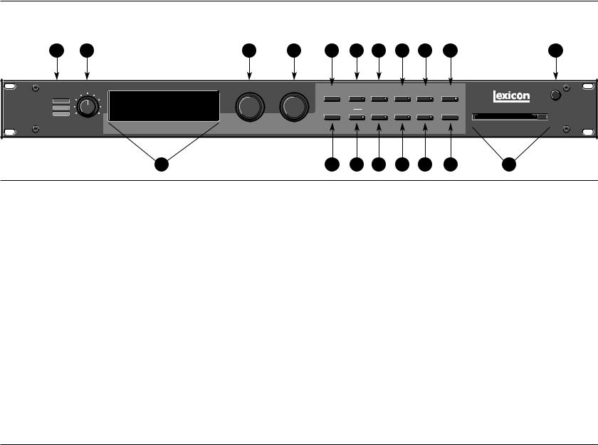
1.Headroom
Five-position indicator for analog and digital signal levels and overload conditions.
2.INPUT
Adjusts analog input level.
3.Display
Two rows of 20 alphanumeric characters display effect names and ID numbers, and parameter names and values.
4.ADJUST
In Edit mode, changes values of parameters chosen with SELECT. With Program Banks or Register Banks selected, behaves as a soft knob for patched parameters.
5.SELECT
Scrolls through presets, registers or parameters. With Program Bank or Register Bank selected, scrolls through the 50 programs in the selected bank, then begins scrolling through the programs in the next bank. With Edit selected, scrolls through matrix parameters.
6.Up/Down
Press to move up and down through program and register banks, or a parameter matrix.
7.Program Banks
Enables selection of factory presets. Press repeatedly to cycle selection of 5 internal preset banks and a KeyWord sorted display. Press and hold to display the name and algorithm of the current program.
1-4

PCM 91
Getting Started
8.Load/
In Program or Register mode, loads the selected program. In Edit mode, scrolls through any multi-field parameter.
9.Register Banks
Enables selection of user memory. If a RAM card is loaded into the Memory Card slot, each press of this button selects a new register bank. Press and hold to display the name and algorithm of the current program.
10.Store
Initiates register store function.
11.Edit
Enables parameter selection for editing of values.
12.Compare
Active in Program, Register, and Edit modes. Press to compare the active version of the current effect with the most recently stored version.
13.Control
Enables selection of system and global parameters.
14.Bypass
Bypasses or mutes audio, depending on the setting of each program's bypass parameter.
15.Tempo
Press to display tempo rate and to initiate tempo functions. LED flashes in time with current tempo rate.
16.Tap
Sets tempo. Press twice in rhythm to establish tempo rate. Press once to reset LFO.
17.Memory Card
Slot for optional preset ROM or register RAM cards. Press Eject button to remove card.
18.POWER
On/Off.
1-5
Getting Started
Lexicon
REAR PANEL OVERVIEW
1 |
3 |
5 |
7 |
|
|
|
PUSH |
|
|
PUSH |
|
INPUT |
PUSHPUSH |
|
|
|
|
FOOT |
FOOT |
L |
LEVEL |
R |
|||
|
|
IN |
|
OUTPUTS |
|
|||||
IN |
OUT |
|
SWITCH CONTROLLER |
|
0dB -20dB |
|
|
|||
|
R |
|
|
|
||||||
|
|
S/PDIF |
|
|
L |
|
UNBAL |
|
|
|
|
|
|
|
|
|
|
|
|
|
|
|
|
OUT |
|
|
|
|
|
|
|
|
|
|
|
|
|
|
BALANCED |
|
|
INPUTS |
|
2 |
4 |
8 |
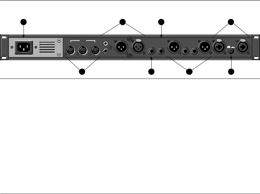
1.AC Power
Standard 3-pin IEC power connector. 100-240V, 50-60Hz automatic switching to correct voltage range.
2.MIDI IN
Receives MIDI information from other MIDI equipment such as master keyboard controllers, MIDI foot controllers, sequencers and synthesizers.
MIDI THRU
Passes received MIDI data without change.
MIDI OUT
Transmits MIDI data to other equipment.
3.AES/EBU and S/PDIF Inputs
AES/EBU format digital connectors conform to AES professional standards. S/PDIF format digital connectors conform to CP-340 Type II and IEC-958 consumer standards. Only one of these options (AES or S/PDIF) may be selected for input.
4.FOOTSWITCH
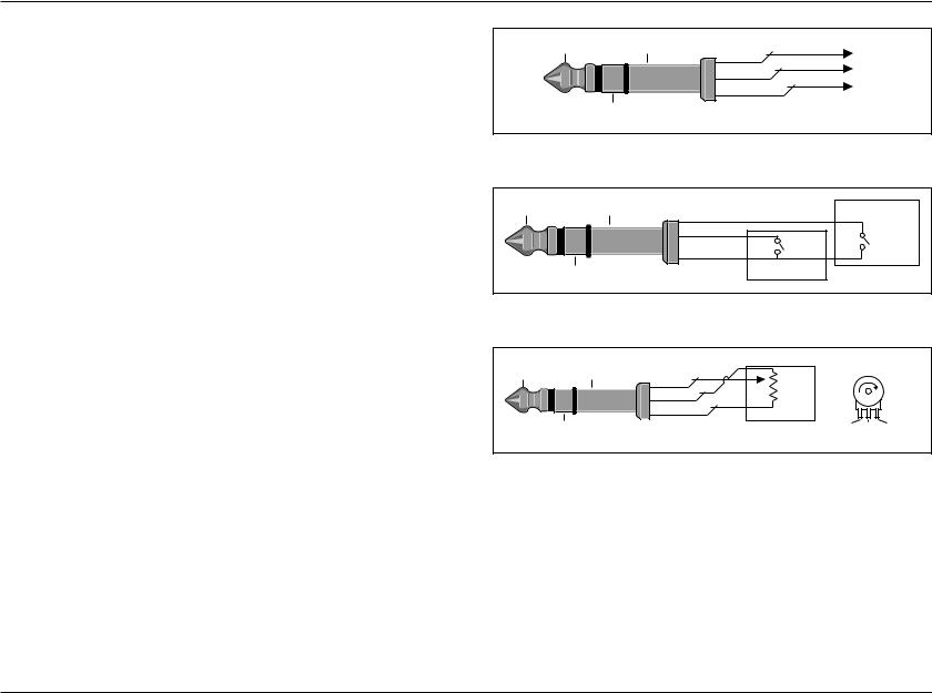
A 1/4” Tip/Ring/Sleeve phone jack for two independent momentary footswitches.
5.FOOT CONTROLLER
1/4" Tip/Ring/Sleeve phone jack provided for footpedal with 10kΩ to 100Ω impedance.
1-6
PCM 91
Getting Started
6.BALANCED OUTPUTS
Output impedance is 105Ω, balanced, and levels up to +18dBu maximum full scale. 1/4" phone connectors and XLRs provided. Both S/PDIF and AES outputs are active at all times.
7.BALANCED INPUTS
Combined 3 pole XLR and 1/4" jacks, electronically balanced. Input impedance is 50kΩ unbalanced, and 100kΩ balanced. Inputs accept input levels from -22dBu to +20dBu.
8.INPUT LEVEL
Two-position (In/Out) switch for matching input gain to the source being used. In position adds 20dB of input gain (unbalanced) to the input stages. Out position provides 0dB of gain (balanced).
Tip |
|
Sleeve |
TIP |
+ |
|
|
|
||
|
|
|
RING |
– |
|
|
|
SLEEVE |
Ground |
|
Ring |
|
Balanced I/O |
(Shield) |
|
|
|
||
|
|
|
|
Tip |
Sleeve |
TIP |
Footswitch 2 |
|
|
||
|
|
RING |
|
Ring |
|
SLEEVE |
Footswitch 1 |
Tip |
Sleeve |
TIP |
|
Typical Pot(entiometer) |
|
|
10-100K |
|
|
|
|
RING |
|
|
|
|
|
|
|
|
Ring |
SLEEVE |
|
|
|
|
PEDAL |
Sleeve Tip Ring |
1-7
Getting Started
Lexicon
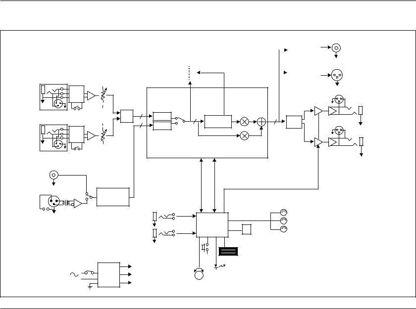
BLOCK DIAGRAM
|
|
|
|
|
|
|
|
|
Digital Audio |
|
Headroom |
|
|
Transmitter |
|||||
|
|
|
|
||||||
|
|
|
|
|
|
|
|
|
|
|
|
|
|
|
|
|
|
|
Digital Audio |
|
|
|
|
|
|
|
|||
Left Input |
|
|
|
|
|
Overload |
|
|
Transmitter |
|
|
|
|
|
|
|
|||
|
|
|
|
|
|||||
|
|
|
|
|
|
|
|
|
|
|
|
|
|
|
|
|
|
|
|
 L/R
L/R
BAL/UNBAL |
Input |
A/D |
L/R |
|
|
|
Analog |
|
|
|
|||
Level |
|
|
|
|||
0dB +20dB |
|
|
|
EFFECTS |
D/A |
|
|
|
Digital |
L/R |
|||
|
|
|
Mix |
L/R |
||
|
|
|
L/R |
|
||
|
|
|
|
|
|
Right Input
S/PDIF In
|
Control |
-10dBu/+4dBu |
AES/EBU In |
Data |
|
|
Digital Audio |
|
|
Receiver |
|
|
|
Footswitch |
|
MIDI IN |
|
|
|
|
MIDI OUT |
||
|
|
|
CPU |
||
|
|
|
MIDI THRU |
||
|
Foot Controller |
|
|||
|
|
PCMCIA |
|||
|
|
|
|
||
|
|
|
|
Memory |
|
|
|
|
Keys |
Card |
|
|
|
|
Display |
||
|
|
|
|
||
100-240V |
Power |
+ 5V |
LEDs |
||
+ 15 |
|||||
50-60 Hz |
Supply |
|
|
||
- 15 |
Soft |
|
|||
|
|
|
|||
|
|
|
Knob |
|
|
S/PDIF Out
AES Out
Left Output |
Right Output
1-8

PCM 91
Getting Started
INSTALLATION NOTES
MOUNTING
The PCM 91 uses one EIA-standard rack space, and can be mounted on any level surface or in a standard 19 inch (483 mm) rack. If the PCM 91 is mounted in a rack or road case, support the rear of the chassis to prevent possible damage from mechanical shock and vibration.
The maximum ambient operating temperature is 104°F (40°C). Provide adequate ventilation if the PCM 91 is mounted in a closed rack with heat-producing equipment such as power amplifiers.
POWER REQUIREMENTS
The PCM 91 is equipped with a 3-pin IEC power connector and detachable cord.
The PCM 91 will operate with power sources from 100 to 240 volts AC, 50-60Hz. Power switching to actual line voltage is automatic.
AUDIO CONNECTIONS
Analog Audio
For best performance, maintain balanced connections, and use high-quality, low-capacitance, twisted-shielded pair cable.
When connecting to single-ended, unbalanced devices, connect the low side to signal ground at the unbalanced piece of equipment. Output level does not change when connected to an unbalanced input.
Mono Applications
Use a Y-connector inserted at the analog inputs and outputs to have the signal summed to mono.
Note:
Be careful to keep input and output to all channels wired consistently. Out-of-phase wiring can produce audible effects.
Digital Audio
S/PDIF (CP-340 Type II) Consumer Digital Audio I/O. 75Ω coaxial cable suited for digital audio or video signals is required. Audio grade cable is not suitable. AES/EBU connections require balanced connections using high quality, low capacitance, controlled impedance, data communication, twisted-shielded pair cable.
Microphone cable may introduce a significant amount of jitter into the signal, causing distortion.
CONTROL CONNECTIONS
Dual Footswitch/Foot Controller
One 1/4 inch T/R/S phone jack is provided for 2 momentary footswitches. Another 1/4 inch T/R/S phone jack is provided for a footpedal (minimum 100Ω to maximum 10kΩ impedance). Normally open or normally closed momentary switches are suitable. At power on, the PCM 91 assumes the switch is off. Use shielded, twisted-pair cable with shield connected to sleeve. See diagram on page 1-7.
1-9
Getting Started
Lexicon
CONTROL CONNECTIONS (continued)
MIDI
Five-pin DIN connectors are provided for MIDI IN, THRU and OUT. Use standard 5-pin DIN MIDI cable assemblies, available from your local dealer.
CONNECTORS
|
Mating |
|
Signal |
Connector |
Description |
|
|
|
L and R Analog |
XLR A3M |
Active balanced, pin 2 high |
Audio Input |
|
+2dBu min; +20dBu max |
|
|
at 0dB setting |
|
|
|
L and R Analog |
XLR A3F |
Active balanced, pin 2 high |
Audio Output |
|
-2dBu to +18dBu |
|
|
at full scale output |
|
|
|
AES/EBU |
XLR A3M |
Balanced RS-422 |
Digital Input |
|
pin 2 high |
|
|
|
AES/EBU |
XLR A3F |
Balanced RS-422 |
Digital Output |
|
pin 2 high |
|
|
|
S/PDIF |
1/4" |
EIAJ Consumer Digital |
CP-340 Type II |
|
Audio Format |
Consumer Digital |
|
tip high |
Audio Input and |
|
|
Output |
|
|
|
|
|
MIDI In |
5-pin DIN |
Standard MIDI Interface |
MIDI Out |
|
|
MIDI Thru |
|
|
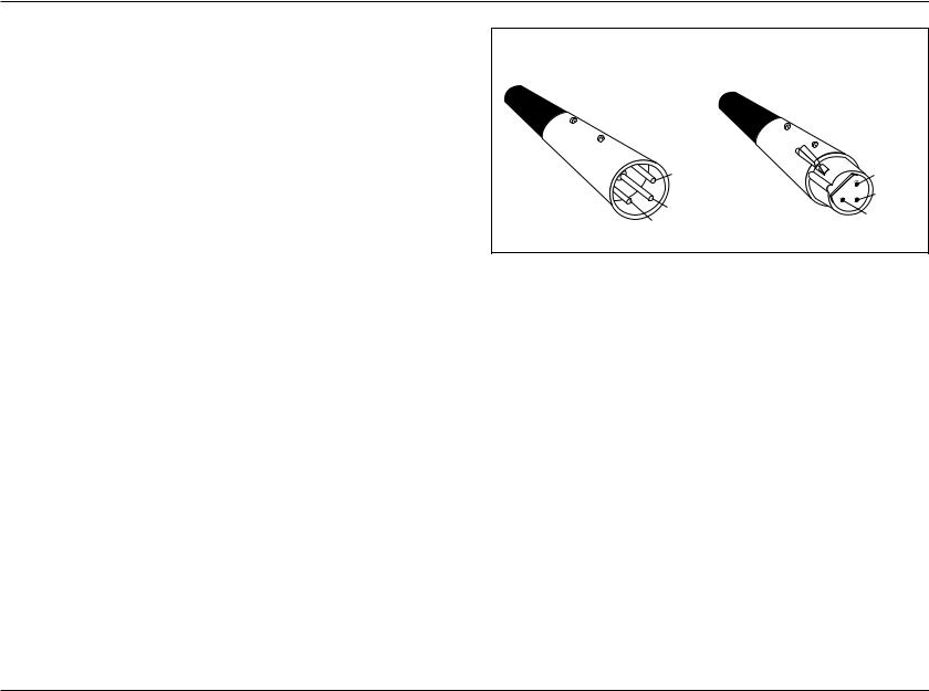
Pin 2 high by convention
2 = high |
Female |
1 = ground |
Male |
|
|
|
|
3 = low |
3 = low
2 = high
1 = ground
SETTING AUDIO LEVELS
The PCM 91, with both analog and digital input and output connections, requires some attention to proper setting of signal level.
Analog inputs are first gain-conditioned by the rear panel input gain switch, and then by the front panel INPUT knob. Proper setting of both the switch and knob are important for best performance of the A/D converter.
Analog and the selected digital sources are selected in Control mode (0.0 Audio Input Source). The selections are: 44.1, 48, Ext: XLR and Ext: Coax.
1-10
PCM 91
Getting Started
Proper setting of Input level on the PCM 91 is dependent on:
•Proper signal level into the analog front end to avoid signals causing overload at the DSP input (rear panel Input Level button),
•Proper adjustment of the signal level into the analog-to-digital converter to optimize noise and avoid overload (front panel INPUT knob),
•Proper setting of signal level into the digital signal processor to optimize noise (InLvl parameter in each algorithm).
Headroom Display
HEADROOM INPUT
0dB 
6
12
18
24  0 10
0 10
The headroom display provides both headroom and overload information from a variety of measurement points. The meters display analog or digital input data, depending on the selected Audio Input Source (Control mode 0.0).
The chart below illustrates the adjustment range that will set input levels for both balanced and unbalanced operation.When a choice can be made, it is best to operate at the higher amplitude end of the recommended range to optimize noise performance.
|
Unbalanced |
Balanced |
overload: |
>+20dBu |
>0dBu |
|
|
|
acceptable: |
+20dBu to -2dBu |
0dBu to -22dBu |
|
|
|
too low (noisy): |
<-2dBu |
<-22dBu |
Overload
The 0db (overload) indicators will light under the following conditions:
•A/D overload
•Overload at any point in effects processing
•Input level within 1dB of maximum
For example, level buildup from certain reverberation modes can result in overload, even when the input A/D or digital receiver data stream is not at full scale. Such conditions are most often caused by a combination of extreme parameter settings. Adjusting parameter/level settings can eliminate these overload conditions.
Selecting a Digital Input Source
1.Press Control.
2.Press Up or Down until the left-most digit in the lower lefthand corner of the display is 0.
3.Turn SELECT to 0.0 Word Clock, and turn ADJUST to display Ext: XLR or Ext: Coax, depending on the input you are using.
1-11
Getting Started
Lexicon
SETTING AUDIO LEVELS (continued)
Setting Input Levels
1.Press Control.
2.Press Up or Down until the left-most digit in the lower lefthand corner of the display is 0.
3.Turn SELECT to 0.0 Audio Input Source.
4.Turn ADJUST to select Analog: 48kHz or Analog: 44.1kHz.
5.Adjust the front panel INPUT knob so that program material level peaks cause the headroom display to reach the top of the column without lighting the overload indicators. An occasional large signal peak causing momentary flashing of the overload indicator is acceptable in most instances, but should be validated by listening to the actual result.
6.Turn ADJUST to select Dig:. The display will show any valid digital format which is properly connected to the PCM 91 rear panel digital input.
Setting Analog Output Level
While still in Control mode, turn SELECT to 0.3 Output Level. The Output Level parameter has two range positions. The appropriate position depends on the level handling capability of the device connected to the analog outputs. Devices capable of handling outputs with peak levels of 18dBu require setting Output Level to the +4dBu setting. Devices which cannot handle peak levels greater than +4dBu require the -10dBu setting.
CONFIGURATIONS
If you will be using a PCM 91 as your primary effects unit, and your system includes a console with one or more auxiliary (effects) sends, connect the PCM 91 as shown at the top of page 1-13. In most applications, it is preferable to connect the PCM 91 outputs to two of the console's input channel strips, panned full left and right, rather than to the effects returns. This allows the greatest flexibility in routing and equalization.
In this configuration the console controls are used to set the amount of effect heard—the PCM 91's MIX control should be set for 100% wet. To assign a global MIX setting:
1.Press Control.
2.Press Up or Down until 1.x is displayed in the lower left of the display and System is displayed on the upper line.
3.Turn SELECT until System Mix Mode is displayed on the upper line. 1.1 will be displayed in the lower left.
4.Turn ADJUST until the lower line reads: 1.1 Global
5.Press Load / to show the current global setting of MIX; use ADJUST to set it to 100% wet.
1-12

PCM 91
Getting Started
Connecting to a Mixing Console’s Effects Sends
Effects Send (R)
Effects Send (L)
Channel Input or Effects Return (L)
Channel Input or Effects Return (R)
|
|
|
|
PUSH |
|
|
PUSHPUSH |
|
INPUT |
PUSHPUSH |
|
|
|
|
|
|
|
L |
LEVEL |
R |
|||
IN |
THRU |
OUT |
IN |
SWITCH CONTROLLER |
BALANCED OUTPUTS |
|
|
0dB -20dB |
|
|
|
|
|
|
S/PDIF |
|
L |
R |
|
|
UNBAL |
|
|
|
|
|
OUT |
|
|
|
|
|
|
|
|
|
|
|
|
|
|
|
BALANCED |
|
|
INPUTS |
|
MEMORY CARDS
You can use Memory cards to store as many as 1000 PCM 91 registers (20 banks of 50 — on a 1 Meg card). Registers stored on a properly formatted card will be recognized whenever the card is inserted, and can be accessed via the front panel Register Banks button, exactly as internal registers.
Memory cards can also be used to store "setups" (your system configuration, as set in Control mode). As many as 5 PCM
91 setups can be stored on a card, allowing you to transport not only your effects, but complete PCM 91 environments to another PCM 91. Cards also provide storage for additional program maps and effect chains.
See Control Mode Store and Load functions for details on saving setups on a card and reloading them.
Memory cards must be of the following type:
PCMCIA SRAM Memory Card — 68 pin, Type I
Usable densities: 64 kByte 128 kByte 256 kByte 1 MByte*
Access Time: 250 nsec or faster
* Cards larger than 1MByte can be used, but the PCM 91 will only make use of 1MByte.
Conforms to PCMCIA 2.0/JEDIA 4.1. Can use either 8-bit or 8/16-bit bus configuration. Attribute memory can be present, but is not used.
1-13

|
2 |
Basic Operation |
|
Modes of Operation...................................................................... |
2-2 |
Navigating a Matrix • Go or Pro • Info • History of Effects Loaded |
|
Control Mode ............................................................................... |
2-5 |
Row 0 Audio • Row 1 System • Row 2 Card • Row 3 MIDI • Row 4 Setup • |
|
Row 5 Mapx • Row 6 Chain |
|
Program and Register Banks........................................................ |
2-17 |
Selecting Effects • Bank and Row Labels • Sorting Effects |
|
Tempo Mode .............................................................................. |
2-20 |
The Tempo Mode Matrix • Row 0 Tempo • Row 1 Tap |
|
Editing an Effect.......................................................................... |
2-22 |
The Soft Knob • The Soft Row • Compare • Bypass • Store Operations •
The Full Edit Matrix • Patching • The Custom Row
Basic Operation
Lexicon
The PCM 91 provides a wide range of control over an extraordinary set of reverb effects. All of the controls are easily accessed from the front panel and are described in detail in this section.
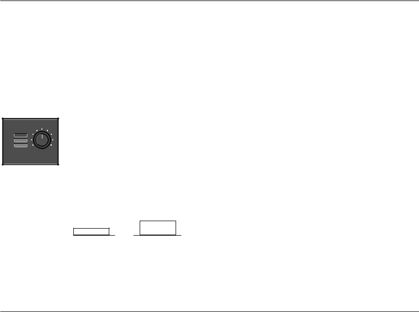
MODES OF OPERATION
The PCM 91 has five basic modes of operation, each of which is selected by pressing a front panel button (Program Banks, Register Banks, Edit, Control and Tempo). Each of these first four mode buttons has an LED which lights when the mode is active. The Tempo LED (unless you elect to have this function turned off) flashes the current tempo. When Tempo mode is active, no other mode LEDs will be lighted.
The PCM 91 always operates in one of these modes. Here, the lit LED indicates that Control Mode is active.
The five mode buttons give you the first level of access to all of the functions and parameters in the PCM 91.
•Press Program Banks repeatedly to access five banks of 50 factory presets and a KeyWord mode where programs can be viewed according to type. The PCM 91's KeyWord function is activated in Control mode.
•Press Register Banks repeatedly to access two banks of 50 memory locations, called registers, where you can store your customized effects. Memory cards can be used for storage of additional banks of registers. When a formatted memory card containing stored registers is inserted, pressing Register Banks repeatedly will cycle through both the internal and the card banks. Registers can be sorted and viewed according to type when the PCM 91's KeyWord function is activated in Control mode.
•Press Edit to access all of the available parameters for the currently running effect.
•Press Control to select system parameters, MIDI, card formatting, etc.
•Press Tempo to set tempo-related values that affect the delay time and LFO rate parameters of the currently-running effect.
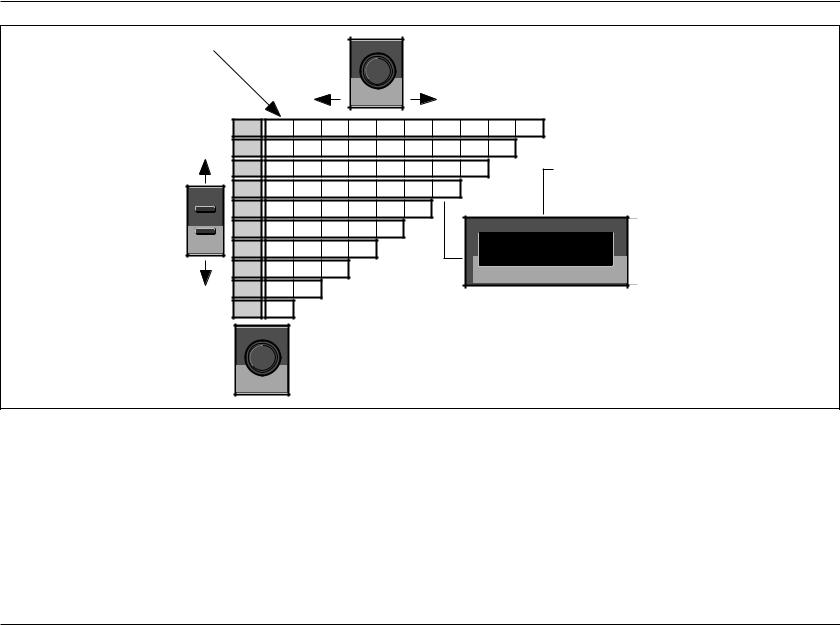
NAVIGATING A MATRIX
All of the controls available in a mode are arranged in a matrix of up to 10 columns (numbered 0-9) and 10 rows (each numbered
.0-.9). This arrangement allows any one of as many as 100 parameters to be selected simply by using the SELECT knob and the Up and Down buttons to select a position in the matrix.
GO OR PRO
The PCM 91 offers a choice between two levels of Edit mode parameter access. We call these Go mode and Pro mode.
Go mode makes use of an extra row in the edit mode matrix called the Soft Row, where you can assign as many as 10 effect parameters or Custom Controls for easy access. Selecting Go mode (Control mode 1.0) limits the action of the Edit button to displaying only the Soft Row parameters assigned to the current effect.
2-2
PCM 91
Basic Operation
Simultaneously pressing Up and Down will always return you to 0.0.
SELECT |
The Select knob moves you horizontally across the matrix.
Navigating a Matrix
The Up and Down buttons move you vertically through the rows of the matrix.
|
0 |
0.0 |
0.1 |
0.2 |
0.3 |
0.4 |
0.5 |
0.6 |
0.7 |
0.8 |
0.9 |
|
1 |
1.0 |
1.1 |
1.2 |
1.3 |
1.4 |
1.5 |
1.6 |
1.7 |
1.8 |
An asterisk in the display indicates that |
|
2 |
2.0 |
2.1 |
2.2 |
2.3 |
2.4 |
2.5 |
2.6 |
2.7 |
|
|
|
|
Load/ is active and, depending on the |
|||||||||
|
3 |
3.0 |
3.1 |
3.2 |
3.3 |
3.4 |
3.5 |
3.6 |
|
|
mode, will load effects or will display |
Up |
4 |
4.0 |
4.1 |
4.2 |
4.3 |
4.4 |
4.5 |
|
|
|
additional parameters when pressed. |
|
|
|
|
|
|||||||
Down |
5 |
5.0 |
5.1 |
5.2 |
5.3 |
5.4 |
|
|
|
PCM 91 |
DIGITAL REVERBERATOR |
|
6 |
6.0 |
6.1 |
6.2 |
6.3 |
|
|
|
|
XXXXXXX XXXXXXXXXX |
|
|
|
|
|
|
3.6 XXXXXXXXXXXXXXXXX |
||||||
|
7 |
7.0 |
7.1 |
7.2 |
|
|
|
|
|
||
|
|
|
|
|
|
|
|
||||
|
8 |
8.0 |
8.1 |
|
|
|
|
|
Your current location in the matrix is shown |
||
|
9 |
9.0 |
|
|
|
|
|
|
|||
|
|
|
|
|
|
|
in the lower lefthand corner of the display. |
||||
|
|
|
|
|
|
|
|
|
|||
|
|
ADJUST |
|
|
|
|
|
|
|
|
|
In the Program and Register Banks, the Adjust knob acts as a soft knob for adjustment of one or more patched effect parameters. In the other modes, Adjust scrolls through the range of available settings for the control you have selected.
Each preset has a set of Soft Row assignments which we've selected for you (as well as an assignment for the ADJUST knob and Custom Controls). When shipped, the PCM 91 will power up in Go mode with the first preset (P0 0.0) loaded. Press Edit to display the Soft Row of parameters. Press Up or Down to access a Pro mode selection display.
Pro mode gives you access to the full parameter matrix, including the Soft Row. Use this mode when you want to do in-depth effects editing or patching, or when you want to customize Soft Row assignments.
Go mode and Pro mode selection is made in Control mode at matrix location 1.0.
2-3
Basic Operation
Lexicon
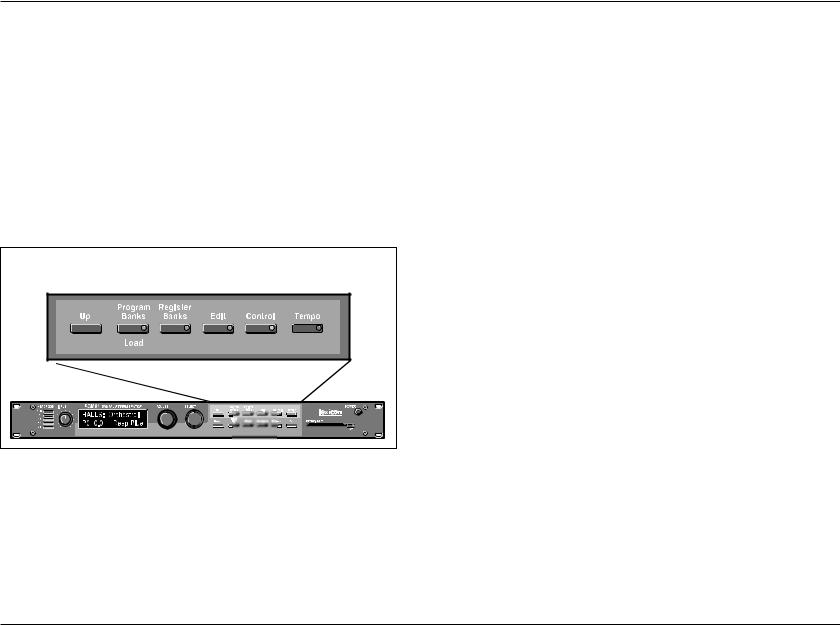
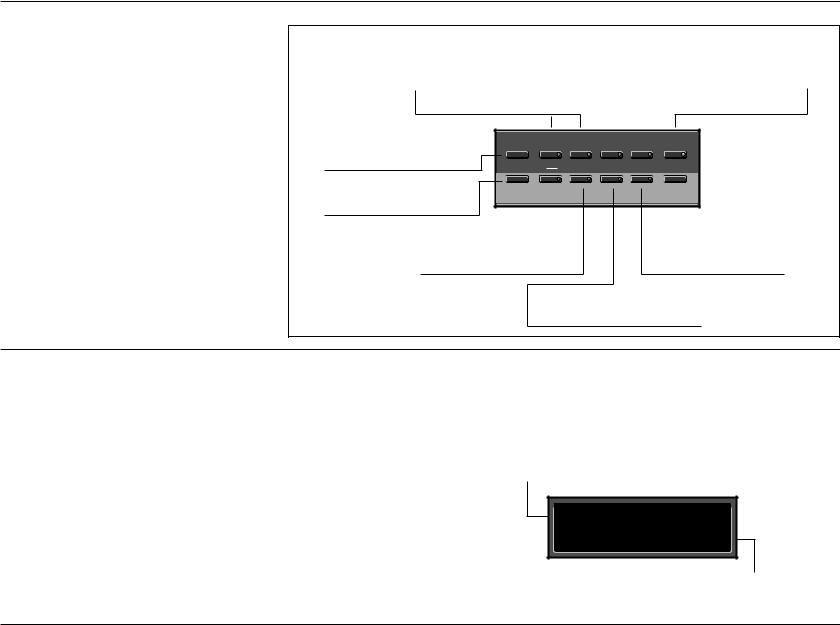
INFO
The PCM 91 offers an extensive set of informative display messages which can be activated from the front panel.
The front panel switches perform various functions when pressed. Most of these functions are activated on release of the button. If you want to know more about the function of a particular button (without actually executing any action) press and hold the button down. While you are holding down the button, an explanatory message will appear on the display. The activation of an Info message overrides the normal function of the button, so that no action is taken on release.
Info messages are displayed when a button is pressed and held down. Generally, info messages describe the
function of a button, or provide current status information.
Displays the currently loaded effect name, bank, and matrix location.
Displays the current tempo and the clock source (MIDI or internal).
Displays the current function |
|
Program |
Register |
|
|
|
assigned to the Up button |
Up |
Banks |
Banks |
Edit |
Control |
Tempo |
|
|
|
|
|
|
|
and the Adjust knob. |
Down |
Load |
Store |
Compare |
Bypass |
Tap |
|
|
|||||
|
|
|
|
|
|
|
Displays the current function |
|
|
|
|
|
|
assigned to the Down button |
|
|
|
|
|
|
and the Select knob. |
|
|
|
|
|
|
Displays action needed to |
|
|
Displays the type of system |
|||
perform a store operation or |
|
|
bypass currently selected, |
|||
Memory Protect message when |
|
|
and the current status |
|||
store function is disabled. |
|
|
(on or off). |
|||
|
|
Inactive until an effect has been |
||||
|
|
altered, then displays "Press to |
||||
|
|
hear stored effect." |
|
|
||
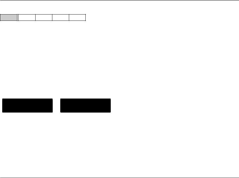
HISTORY OF EFFECTS LOADED
The PCM 91 allows you to review the last ten effects loaded. This is useful when you want to return to an effect you were using earlier, but can't remember its name or location. This History view is accessed from Program Banks or Register Banks mode by simultaneously pressing and releasing both the Program Banks and the Register Banks buttons. The display pictured at the right will appear.
The label 1 back in the example, means that the effect shown on the bottom line was running just before the current effect. Turning SELECT to the right will scroll you through the stored list of effects, all the way to 10 back. Press Load/ to load any of the displayed programs. Press any key to exit.
Note that loading programs from the review display does not update the historical record, nor does loading from MIDI, Chain or Map. Only program loads from Programs Banks or Register Banks mode are recorded.
The top line of the display shows the position in the review list of the displayed effect.
History: 1 back
XX X.X XXXXXXXXXXX
The bottom line of the display shows the bank and matrix location and the name of the effect.
2-4

PCM 91
Basic Operation
CONTROL MODE
Simultaneously press Up and Down to return to 0.0.
0 |
|
0.0 |
0.1 |
0.2 |
0.3 |
0.4 |
0.5 |
0.6 |
|
|
|
Audio |
|
*Word Clock |
Analog In Lvl |
Dig In Lvl |
Word Size |
SCMS |
Emphasis Bit |
Output Level |
|
|
|
|
|
|
|
|
|
|
|
|
|
|
|
1 |
|
1.0 |
1.1 |
1.2 |
1.3 |
1.4 |
1.5 |
1.6 |
1.7 |
1.8 |
|
System |
|
Edit Mode |
Mix Mode |
Tempo Mode |
Bypass Mode |
Pgm Bypass |
Mem Protect |
Auto Load |
Patch Update |
Initialize |
|
|
|
|
|
|
|
|
|
|
|
|
|
2 |
|
2.0 |
2.1 |
2.2 |
|
|
|
|
|
|
|
Card |
|
Bank Copy |
Load |
Format |
|
|
|
|
|
|
|
|
|
|
|
|
|
|
|
|
|
|
|
3 |
|
3.0 |
3.1 |
3.2 |
3.3 |
3.4 |
3.5 |
3.6 |
3.7 |
3.8 |
3.9 |
MIDI |
|
Reset |
Receive |
Transmit |
*Pgm Change |
Automation |
*Send |
Int Clock |
SysEx |
Dump |
Dump Speed |
|
|
|
|
|
|
|
|
|
|
|
|
4 |
|
4.0 |
4.1 |
|
|
|
|
|
|
|
|
Setup |
|
Store |
Load |
|
|
|
|
|
|
|
|
|
|
|
|
|
|
|
|
|
|
|
|
Mapx |
|
Map 0 |
Map 1 |
|
|
|
|
|
|
|
|
|
|
|
|
|
|
|
|
|
|
|
|
Chain |
|
Chain |
|
|
|
|
|
|
|
|
|
|
Pgm Assign |
|
|
|
|
|
|
|
|
|
|
|
|
Chain 0 |
Chain 1 |
Chain 2 |
Chain 3 |
Chain 4 |
Chain 5 |
Chain 6 |
Chain 7 |
Chain 8 |
Chain 9 |
An asterisk ( ) accompanying a parameter name indicates available subparameters at that matrix location. The Load/ LED will light when an asterisk appears on the display. Press Load/ to step to the next subparameter. From any point in the matrix, press Up or Down together with Load/ to backstep to the previous parameter.
Selections of various system states and conditions are made in Control Mode. Press Control to enter this mode. The Control button LED will light to indicate that the mode is active. Note that Control Mode functions are not available when the Compare function is active.
The Control Mode matrix is shown above. Following are descriptions of each available selection.
2-5
Basic Operation
Lexicon
ROW 0 AUDIO |
|
|
|
|
0 |
0.0 |
0.1 |
0.2 |
0.3 |
Audio |
*Input Source |
SCMS |
Emphasis Bit |
Outpu Level |
0.0 Input Source
The PCM 91 can use its own internal clock as a timing reference, or it can reference an external clock source from the rear panel S/PDIF or AES jacks. Use ADJUST to select Ext XLR (AES), Ext Coax (S/PDIF), Int: 48kHz or Int: 44.1kHz. When either analog rate is selected, the digital input is disabled. To process audio from the digital input, you must select Ext.
When External clock is selected, and the PCM 91 detects valid digital audio, the rate of the external word clock will be displayed with a label indicating the digital audio format type: Prf (Professional) or Cns (Consumer, also called S/PDIF).
Audio |
Input Source |
|
Audio |
Input Source |
0.0 Ext: |
XLR Prf 48 |
|
0.0 Ext: |
Cns 48kHz |
|
|
|
|
|
When the PCM 91 is receiving valid digital audio, selecting Input Source will display the input connector, audio format, and the rate of the incoming signal.
When digital clock is selected, any loss of lock detected in the incoming digital audio, or reception of non-audio data will cause the PCM 91 to immediately mute the digital input and switch to internal clock at the sample rate of the last valid external signal. An error message will be displayed if this occurs. The PCM 91 will repeatedly try to establish lock, returning automatically to External clock if and when lock is confirmed.
The following types of errors are detected when the PCM 91 is set to Ext:
•No Lock: The PCM 91, at some point, lost lock to the
incoming digital audio signal. Digital audio input is muted.
•Out of Range: The sampling rate of the incoming audio
signal is outside of acceptable tolerance limits of +4%. Digital audio input is muted.
•Non Audio: Indicates transmission of non-audio data, such
as from a CD ROM. Digital audio input is muted.
•CRC: The error is reported, but incoming audio is
accepted.
Dig In Status
Pressing Load/ from Input Source will display the current digital input status. This status display is continuously updated, acting as a real-time monitor of the PCM 91 digital input. This display is active even when the PCM 91 is set to Internal clock. Note that in the case of an AES Pro format signal, "Emp:Yes" means either CCITT or 50/15µs emphasis.
If valid digital audio is detected, the display will show the external clock rate and format information, along with the status of the Emphasis bit(s) in the incoming audio signal. If the PCM 91 has lost lock, the display message will indicate "No Lock" and parenthetically show the internal clock rate now in use.
Upon loss of lock, or reception of non-audio data, the PCM 91 will mute the digital input and display the following messages when Input Source or Dig In Status is selected:
2-6

PCM 91
Basic Operation
Input Source |
Dig In Status |
Not Locked |
No Lock (Int 44.1) |
|
|
Out of Range |
No Lock (Int 44.1) |
|
|
Non Audio: 44.1 |
Non Audio: 44.1 |
Error Log |
|
|
|
|
|
|
|
|
|
Audio |
Dig In Status |
|
Audio |
Dig In Status |
0.0 Prf |
44.1 Emp:Yes |
|
0.0 No Lock (Int:44.1) |
|
|
|
|
|
|
When the PCM 91 loses lock, it will mute the digital input.
The following errors are continuously logged and are available for review by pressing Load/ from the Dig In Status display and using ADJUST to scroll through the error list.
•Validity: A Validity error indicates that the Validity bit
was set in a frame of incoming data and that the data attached to it may be corrupted. This bit may also be sent when the transmitting device is paused.
•Confidence: The PCM 91 is detecting excessive jitter or
noise on the digital audio line. No data has been corrupted, but corrective action should be taken.
•SlipSample: Indicates that a single sample is misaligned
with the window defined by the Input Source. This may occur when an external master changes sample rate, or when it is just powering up, but should not occur in normal operation. (This type of error is reported for reference only, as the PCM 91 does not accept digital data when using its own internal clock.)
•CRC: Indicates a Cyclic Redundancy Check error in
|
the incoming data. |
• Parity, |
Indicate that at least one bit (and therefore at |
Biphase: |
least one audio sample) was corrupted. |
Parity, Biphase, and Confidence errors are most often caused by inappropriate cabling. Be sure to use 75Ω video-grade cable, kept as short as possible — standard audio cable will not work reliably.
Each error is reported by name, with the number of occurrences of that particular type of error. The display might show, for example "CRC: 4752". As many as 9999 instances of each error can be shown. If the number of actual errors exceeds 9999, the display will indicate ">9999". A special symbol (n) before the error type indicates the most recently received error.
Press Load/ from the Dig In Status display and use ADJUST to scroll through the Error Log.
A typical Error Log display showing that the |
|
|
|
|
|
last error received was a CRC error (■ CRC) |
Audio |
Error Log |
and that there have been more than (>) |
0.0 |
CRC >9999 |
9999 instances of CRC errors since Word |
||
Clock was last set to Ext. |
|
|
To clear the Error Log, reselect Dig from the Control Mode Input Source display. This will cause the PCM 91 to attempt to lock to the current external source and will reset the Error Log. The log is also cleared on power up, and whenever it relocks (Auto Lock On).
2-7
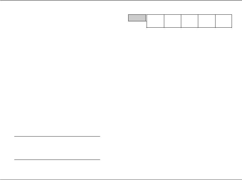
Basic Operation
Lexicon
ROW 0 AUDIO (continued)
0.1 SCMS
Digital audio signals, in order to comply with copyright standards, are encoded with control information which can limit the ability to copy audio data. This control information is generally known as SCMS (Serial Copy Management System). Under this system, you can choose to have the audio material processed by the PCM 91 encoded to allow one of three levels of copy restriction. To make your selection, use ADJUST to select No Copy, One Copy, or Multi Copy.
0.2 Emphasis Bit
The Emphasis control allows you to explicitly set the emphasis "flag" in the digital audio, or to pass along the incoming signal without changing its emphasis coding. (The PCM 91 does not perform any emphasis or de-emphasis as part of its signal processing.) The choices available with ADJUST are: Yes, No, and Pass Thru.
0.3 Output Level
This control allows you to select the maximum output level at the PCM 91's analog outputs. Use ADJUST to select +4 dBu, or –10 dBu.
Note:
Exercise care when switching this control, as a 14dB level change instantly occurs when going from -10dBu to +4dBu.
ROW 1 SYSTEM |
|
|
|
|
|
1 |
1.0 |
1.1 |
1.2 |
1.3 |
1.4 |
System |
Edit Mode |
Mix Mode |
Tempo Mode |
*Bypass Mode |
Pgm Bypass |
|
1.5 |
1.6 |
1.7 |
1.8 |
1.9 |
|
Mem Protect |
Auto Load |
Patch Update |
*KeyWord |
Initialize |
1.0 Edit Mode
The PCM 91 has been designed with a "plug and play" feature called Go mode. In this mode, the most useful parameters of each effect are grouped together in a single row which is available whenever you press Edit.
Each PCM 91 preset has a set of Go mode parameters which we've selected for you. When shipped, the PCM 91 will power up in Go mode, with the first preset (P0 0.0) loaded. Press Edit to display the first available parameter in the Soft Row.
If you want access to the full parameter matrix for any effect, including the Soft Row parameters, use ADJUST to select Pro mode. Now, when Edit is pressed, you can select any parameter for adjustment, and customize any effect with your own Soft Row assignments. For more information about the Soft Row, see Editing an Effect later in this chapter.
1.1 Mix Mode
Each PCM 91 effect has its own Mix parameter, with the Mix setting stored as an integral part of the effect. Mix Mode allows you to override these individual Mix settings and set a global Mix value for all effects. This is useful when using a mixing console's controls to set the amount of wet signal in a mix. In such a case, you can use this control to set all PCM 91 effects to 100% wet.
2-8
 Loading...