


 MX300 Stereo Reverb
Effects Procesor
MX300
User
Guide
IMPORTANT SAFETY INSTRUCTIONS
The symbols shown above are internationally accepted symbols that warn of potential hazards with electrical products. The lightning flash with arrowpoint in an equilateral triangle means that there are dangerous voltages present within the unit. The exclamation point in an equilateral triangle indicates that it is necessary for the user to refer to the owner’s manual.
These symbols warn that there are no user serviceable parts inside the unit. Do not open the unit. Do not attempt to service the unit yourself. Refer all servicing to qualified personnel. Opening the chassis for any reason will void the manufacturer’s warranty. Do not get the unit wet. If liquid is spilled on the unit, shut it off immediately and take it to a dealer for service. Disconnect the unit
during storms to prevent damage.
The following is indicative of low altitude use; do not use this product above 2000m.
U.K. MAINS PLUG WARNING
A molded mains plug that has been cut off from the cord is unsafe. Discard the mains plug at a suitable disposal facility.
NEVER UNDER ANY CIRCUMSTANCES SHOULD YOU INSERT A DAMAGED OR CUT MAINS PLUG INTO A 13 AMP POWER SOCKET.
Do not use the mains plug without the fuse cover in place. Replacement fuse covers can be obtained from your local retailer. Replacement fuses are 13 amps and MUST be ASTA approved
to BS1362.
If you want to dispose this product, do not mix it with general household waste. There is a separate collection system for used electronic products in accordance with legislation that requires proper treatment, recovery and recycling.
Private households in the 25 member states of the EU, in Switzerland and Norway may return their used electronic products free of charge to designated collection facilities or to a retailer (if you purchase a similar new one).
For Countries not mentioned above, please contact your local authorities for a correct method of disposal.
By doing so you will ensure that your disposed product undergoes the necessary treatment, recovery and recycling and thus prevent potential negative effects on the environment and human health.
WARNING FOR YOUR PROTECTION
READ THE FOLLOWING:
READ THESE INSTRUCTIONS.
KEEP THESE INSTRUCTIONS.
HEED ALL WARNINGS.
FOLLOW ALL INSTRUCTIONS.
DO NOT USE THIS APPARATUS NEAR WATER.
CLEAN ONLY WITH A DRY CLOTH.
FOR INDOOR USE ONLY.
DO NOT BLOCK ANY OF THE VENTILATION OPENINGS. INSTALL IN ACCORDANCE WITH THE MANUFACTURER’S INSTRUCTIONS.
DO NOT INSTALL NEAR ANY HEAT SOURCES SUCH AS RADIATORS, HEAT REGISTERS, STOVES, OR OTHER APPARATUS (INCLUDING AMPLIFIERS) THAT PRODUCE HEAT.
ONLY USE ATTACHMENTS/ACCESSORIES SPECIFIED BY THE MANUFACTURER.
UNPLUG THIS APPARATUS DURING LIGHTNING STORMS OR WHEN UNUSED FOR LONG PERIODS OF TIME.
Do not defeat the safety purpose of the polarized or grounding-type plug. A polarized plug has two blades with one wider than the other. A grounding type plug has two blades and a third grounding prong. The wide blade or third prong are provided for your safety. If the provided plug does not fit your outlet, consult an electrician for replacement of the obsolete outlet.
Protect the power cord from being walked on or pinched particularly at plugs, convenience receptacles, and the point where they exit from the apparatus.
Use only with the cart stand, tripod bracket, or table specified by the manufacture, or sold with the apparatus. When a cart is used, use caution when moving the cart/apparatus combination to avoid injury from tip-over.
Refer all servicing to qualified service personnel. Servicing is required when the apparatus has been damaged in any way, such as power-supply cord or plug is damaged, liquid has been spilled or objects have fallen into the apparatus, the apparatus has been exposed to rain or moisture, does not operate normally, or has been dropped.
POWER ON/OFF SWITCH: The Power switch used in this piece of equipment DOES NOT break the connection from the mains.
MAINS DISCONNECT: The plug shall remain readily operable. For rack-mount or installation where plug is not accessible, an all-pole mains switch with a contact separation of at least 3 mm in each pole shall be incorporated into the electrical installation of the rack or building.
If connected to 240V supply, a suitable CSA/UL certified power cord shall be used for this supply.
This Equipment is intended for rack mount use only.

IMPORTANT SAFETY INSTRUCTIONS
MX300
ELECTROMAGNETIC COMPATIBILITY
This device complies with part 15 of the FCC Rules and the Product Specifications noted on the Declaration of Conformity. Operation is subject to the following two conditions:
•this device may not cause harmful interference, and
•this device must accept any interference received, including interference that may cause undesired operation.
Operation of this unit within significant electromagnetic fields should be avoided.
• use only shielded interconnecting cables.
SAFETY INSTRUCTIONS
NOTICE FOR CUSTOMERS IF YOUR UNIT IS EQUIPPED WITH A POWER CORD.
WARNING: THIS APPLIANCE SHALL BE CONNECTED TO A MAINS SOCKET OUTLET WITH A PROTECTIVE EARTHING CONNECTION.
THE CORES IN THE MAINS LEAD ARE COLOURED IN ACCORDANCE WITH THE FOLLOWING CODE:
GREEN AND YELLOW - EARTH BLUE - NEUTRAL BROWN - LIVE
AS COLOURS OF THE CORES IN THE MAINS LEAD OF THIS APPLIANCE MAY NOT CORRESPOND WITH THE COLOURED MARKINGS IDENTIFYING THE TERMINALS IN YOUR PLUG, PROCEED AS FOLLOWS:
•THE CORE WHICH IS COLOURED GREEN AND YELLOW MUST BE CONNECTED TO THE TERMINAL IN THE PLUG MARKED WITH THE LETTER E, OR WITH THE EARTH SYMBOL, OR COLOURED GREEN, OR GREEN AND YELLOW.
•THE CORE WHICH IS COLOURED BLUE MUST BE CONNECTED TO THE TERMINAL MARKED N OR COLOURED BLACK.
•THE CORE WHICH IS COLOURED BROWN MUST BE CONNECTED TO THE TERMINAL MARKED L OR COLOURED RED.
THIS EQUIPMENT MAY REQUIRE THE USE OF A DIFFERENT LINE CORD, ATTACHMENT PLUG, OR BOTH, DEPENDING ON THE AVAILABLE POWER SOURCE AT INSTALLATION. IF THE ATTACHMENT PLUG NEEDS TO BE CHANGED, REFER SERVICING TO QUALIFIED SERVICE PERSONNEL WHO SHOULD REFER TO THE TABLE BELOW. THE GREEN/YELLOW WIRE SHALL BE CONNECTED DIRECTLY TO THE UNITS CHASSIS.
|
CONDUCTOR |
WIRE COLOR |
||
|
|
|
Normal |
Alt |
L |
|
LIVE |
BROWN |
BLACK |
N |
|
NEUTRAL |
BLUE |
WHITE |
E |
|
EARTH GND |
GREEN/YEL |
GREEN |
|
|
|
|
|
WARNING: IF THE GROUND IS DEFEATED, CERTAIN FAULT CONDITIONS IN THE UNIT OR IN THE SYSTEM TO WHICH IT IS CONNECTED CAN RESULT IN FULL LINE VOLTAGE BETWEEN CHASSIS AND EARTH GROUND. SEVERE INJURY OR DEATH CAN THEN RESULT IF THE CHASSIS AND EARTH GROUND ARE TOUCHED SIMULTANEOUSLY.
WARNING:
•APPARATET MÅ TILKOPLES JORDET STIKKONTAKT.
•APPARATEN SKALL ANSLUTAS TILL JORDAT UTTAG.
•LAITE ON LIITETTÄVÄ SUOJAKOSKETTIMILLA VARUSTETTUUN PISTORASIAAN.
DECLARATION OF CONFORMITY
Manufacturer’s Name: |
Lexicon Professional |
Manufacturer’s Address: |
10653 South River Front Parkway |
|
Suite 300 South Jordan, Utah |
|
84095, USA |
declares that the product: |
|
Product name: |
Lexicon MX300 |
Note: Product name may be suffixed by the EU. |
|
Product option: |
None |
conforms to the following Product Specifications: |
|
Safety: |
IEC 60065 -01+Amd 2 |
EMC: |
EN 55022:2006 |
|
EN 55024:1998 |
|
FCC Part 15 |
Supplementary Information:
The product herewith complies with the requirements of the: Low Voltage Directive 2006/95/EC
EMC Directive 2004/108/EC. RoHS Directive 2011/65/EC WEEE Directive 2002/96/EC
With regard to Directive 2005/32/EC and EC Regulation 1275/2008 of 17 December 2008, this product is designed, produced, and classified as Professional Audio Equipment and thus is exempt from this Directive.
Rex C. Reed
Director, Engineering
Signal Processing
10653 South River Front Parkway
Suite 300
South Jordan, Utah 84095, USA
Date: August 15, 2014
European Contact: Your local Lexicon Sales and Service Office or:
Harman Signal Processing
10653 South River Front Parkway
Suite 300
South Jordan, Utah 84095, USA
Ph: (801) 566-8800
Fax: (801) 568-7583

CONSIGNES DE SÉCURITÉ IMPORTANTES
Les symboles illustrés ci-dessus sont des symboles acceptés internationalement qui avertissent des dangers potentiels relatifs à l’utilisation de produits électriques. Le voyant clignotant avec une flèche dans un triangle équilatéral signifie la présence de tensions dangereuses dans l'appareil. Le point d’exclamation dans un triangle équilatéral indique que l’utilisateur doit se référer au manuel d'utilisation.
Ces symboles indiquent qu’il n’y a aucune pièce utilisable par l’utilisateur à l’intérieur de l’appareil. Ne pas ouvrir l’appareil. Ne pas essayer de réparer soi-même l’appareil. Confier toute réparation à du personnel qualifié. Ouvrir la structure de l’appareil pour quelque raison que ce soit annulera la garantie du fabricant. Ne pas mouiller l’appareil. Si du liquide est renversé sur l’appareil, fermer immédiatement l’appareil et l’apporter chez un réparateur. Débrancher l’appareil pendant les tempêtes afin d’éviter
des dommages.
Ce qui suit est représentatif d’une utilisation à basse altitude ; ne pas utiliser ce produit audessus de 2000 m.
AVERTISSEMENT CONCERNANT
LA FICHE SECTEUR
Une fiche secteur moulée qui a été coupée du cordon est dangereuse. Jeter la fiche secteur dans un centre de déchets adapté.
VOUS NE DEVEZ EN AUCUNE CIRCONSTANCE INSÉRER UNE FICHE ENDOMMAGÉE OU COUPÉE DANS UNE PRISE SECTEUR 13 AMP.
Ne pas utiliser la fiche secteur si le couvercle du coffret à fusibles n'est pas bien en place. Vous pouvez vous procurer des capots de fusible de rechange auprès de votre détaillant local. Les fusibles de remplacement sont de 13 A et DOIVENT être approuvés ASTA, BS1362.
Ne pas jeter ce produit avec les ordures ménagères. Il existe un système de collecte sélective pour les produits électroniques usagés en conformité avec les lois en vigueur en matière de traitement, de récupération et de recyclage.
Dans les 25 États membres de l’UE, en Norvège et en Suisse, les ménages peuvent envoyer leurs produits électroniques usagés sans frais vers des centres de collecte sélective ou chez un distributeur (contre l’achat d’un nouveau produit).
Contacter les autorités locales pour connaître les procédures de traitement des déchets adaptées dans les pays non mentionnés ci-dessus.
Non seulement cette précaution vous permettra d’être sûr que votre produit est correctement traité, récupéré et recyclé,
mais elle vous évitera également de nuire involontairement à l’environnement et à la santé humaine.
AVERTISSEMENT POUR VOTRE SÉCURITÉ
LIRE ATTENTIVEMENT :
LIRE CES CONSIGNES.
CONSERVER CES CONSIGNES.
RESPECTER TOUS LES AVERTISSEMENTS.
SUIVRE TOUTES LES CONSIGNES.
NE PAS UTILISER CET APPAREIL PRÈS DE L’EAU.
NETTOYER UNIQUEMENT AVEC UN CHIFFON SEC.
POUR USAGE INTÉRIEUR UNIQUEMENT.
NE PAS OBSTRUER LES OUÏES D’AÉRATION. EFFECTUER L’INSTALLATION CONFORMÉMENT AUX INSTRUCTIONS DU FABRICANT.
NE PAS INSTALLER À PROXIMITÉ DE SOURCES DE CHALEUR TELLES QUE DES RADIATEURS, BOUCHES D’AÉRATION, PLAQUES CHAUFFANTES OU TOUT AUTRE APPAREIL (Y COMPRIS DES AMPLIFICATEURS) DÉGAGEANT DE LA CHALEUR.
UTILISER UNIQUEMENT LES PIÈCES/ACCESSOIRES MENTIONNÉS PAR LE FABRICANT.
DÉBRANCHER L'APPAREIL AU COURS DES ORAGES OU EN CAS DE NON-UTILISATION PENDANT UNE DURÉE PROLONGÉE.
Ne pas détériorer la sécurité de la fiche polarisée ou de la fiche de terre. Les fiches polarisées sont équipées de deux bornes de largeurs différentes. Les fiches de terre comportent deux lames et une troisième broche de mise à la terre. La broche la plus large ou troisième broche de mise à la terre est prévue pour votre sécurité. Si la fiche fournie ne correspond pas à votre installation électrique, faire appel à un électricien pour remplacer la prise hors normes.
Protéger le cordon d'alimentation contre les risques de piétinement ou de pincement, notamment au niveau des fiches, des prises de courant et du point d'attache avec le matériel.
Utiliser uniquement le chariot, le support, le trépied ou la table spécifié(e) par le fabricant ou vendu(e) avec le matériel. Si vous utilisez un chariot pour déplacer l'appareil, soyez suffisamment prudent pour éviter une éventuelle blessure consécutive au basculement du chariot et de sa charge.
Les réparations doivent être confiées à un technicien S.A.V. qualifié. Une réparation est nécessaire en cas de dommage quelconque et en particulier en cas d'endommagement du cordon d’alimentation ou de la fiche électrique, d'infiltration liquide, d'introduction involontaire d'un objet dans l'appareil, d'exposition de l’appareil à la pluie ou à un milieu humide, de fonctionnement anormal ou de chute de l'appareil.
INTERRUPTEUR MARCHE/ARRÊT : l'interrupteur d'alimentation de cet équipement NE coupe PAS la connexion secteur.
DÉBRANCHEMENT DE L'APPAREIL : la prise de courant doit rester facilement accessible. Pour un montage en rack ou une installation avec une prise inaccessible, un interrupteur omnipolaire à distance d'ouverture de contact d'au moins 3 mm doit être intégré à l’installation électrique du rack ou du local.
Si le matériel est relié à une alimentation de 240 V, utiliser impérativement un cordon d'alimentation adapté certifié CSA/UL pour ce branchement.
Cet équipement est exclusivement destiné à un montage en rack.

CONSIGNES DE SÉCURITÉ IMPORTANTES
COMPATIBILITÉ ÉLECTROMAGNÉTIQUE
Cet appareil est conforme au volet 15 des règles du FCC et aux spécifications techniques évoquées dans la Déclaration de conformité. Son fonctionnement est soumis aux deux conditions suivantes :
•cet appareil ne doit pas causer d’interférences nuisibles et
•cet appareil doit accepter les interférences captées, y compris les interférences susceptibles de nuire à son fonctionnement.
L’utilisation de cet appareil à proximité de champs électromagnétiques puissants n’est pas recommandée.
•utiliser exclusivement des câbles d’interconnexion blindés.
CONSIGNES DE SÉCURITÉ
NOTICE ADRESSÉE AUX CONSOMMATEURS ÉQUIPÉS D’UN MATÉRIEL AVEC CORDON D’ALIMENTATION FOURNI.
AVERTISSEMENT : CET APPAREIL DOIT ÊTRE BRANCHÉ SUR UNE PRISE SECTEUR DOTÉE D'UNE PROTECTION PAR MISE À LA TERRE.
LES COULEURS DES NOYAUX DANS LES FILS SECTEURS DOIVENT RESPECTER LES CODES
SUIVANTS : |
|
|
|
|
|
VERT ET JAUNE - TERRE |
BLEU - NEUTRE |
MARRON - PHASE |
LES COULEURS DES NOYAUX DANS LES FILS SECTEURS DE CET APPAREIL PEUVENT NE PAS CORRESPONDRE AUX INSCRIPTIONS COLORÉES IDENTIFIANT LES TERMINAUX DANS VOTRE FICHE ; IL FAUT DONC PROCÉDER DE LA FAÇON SUIVANTE :
•LE NOYAU VERT ET JAUNE DOIT ÊTRE BRANCHÉ AU TERMINAL DE LA FICHE OÙ APPARAÎT LA LETTRE E OU LE SYMBOLE DE MISE À LA TERRE, OU AU TERMINAL VERT OU VERT ET JAUNE.
•LE NOYAU BLEU DOIT ÊTRE BRANCHÉ AU TERMINAL MARQUÉ D’UN N OU DE COULEUR NOIRE.
•LE NOYAU MARRON DOIT ÊTRE BRANCHÉ AU TERMINAL MARQUÉ D’UN L OU DE COULEUR ROUGE.
CE MATÉRIEL PEUT NÉCESSITER L’UTILISATION D’UN CORDON D’ALIMENTATION DIFFÉRENT ET/OU D’UNE FICHE DE BRANCHEMENT DIFFÉRENTE SELON LA SOURCE D’ALIMENTATION DISPONIBLE À L’INSTALLATION. SI LA FICHE DE BRANCHEMENT DOIT ÊTRE CHANGÉE, FAIRE APPEL À UN TECHNICIEN QUALIFIÉ QUI DEVRA SE RÉFÉRER AU TABLEAU CI-DESSOUS. LE FIL VERT/JAUNE DOIT ÊTRE BRANCHÉ DIRECTEMENT AU CHÂSSIS DE L'APPAREIL.
CONNECTEURS |
COULEUR DU FIL |
|||
normal |
Alt |
|||
|
|
|||
L |
PHASE |
MARRON |
NOIR |
|
N |
NEUTRE |
BLEU |
BLANC |
|
E |
TERRE |
VERT/JAU |
VERT |
|
ATTENTION : UN DÉFAUT DE MISE À LA TERRE PEUT PROVOQUER CERTAINS DYSFONCTIONNEMENTS DE L'APPAREIL OU DU SYSTÈME AUQUEL IL EST RELIÉ, POUVANT SE TRADUIRE PAR UNE TENSION COMPOSÉE ENTRE LA MASSE ET LA PRISE DE TERRE. CELA PEUT PROVOQUER DES BLESSURES SÉRIEUSES OU FATALES SI LA MASSE ET LA PRISE DE TERRE SONT TOUCHÉES EN MÊME TEMPS.
ATTENTION :
•APPARATET MÅ TILKOPLES JORDET STIKKONTAKT.
•APPARATEN SKALL ANSLUTAS TILL JORDAT UTTAG.
•LAITE ON LIITETTÄVÄ SUOJAKOSKETTIMILLA VARUSTETTUUN PISTORASIAAN.
DÉCLARATION DE CONFORMITÉ
Nom du fabricant : |
Lexicon Professional |
Adresse du fabricant : |
10653 South River Front Parkway |
|
Suite 300 South Jordan, Utah |
|
84095, ÉTATS-UNIS |
|
|
déclare que le produit : |
|
|
|
Nom du produit : |
Lexicon MX300 |
Remarque : Le nom du produit peut être suivi des lettres UE. |
|
Option du produit : |
Aucune |
est conforme aux spécifications suivantes :
Sécurité : CEI/IEC 60065:2001 + Amd 2
CEM : EN 55022:2006 EN 55024:1998 Partie 15 des FCC
Informations complémentaires :
Ce produit est conforme aux exigences suivantes : Directive sur la basse tension 2006/95/CE Directive 2004/108/CE.
Directive RoHS 2011/65/UE Directive DEEE 2002/96/CE
Ce produit appartenant à la catégorie Matériel audio professionnel, il n'est pas concerné par la directive 2005/32/CE ou par le règlement européen 1275/2008 du 17 décembre 2008.
Rex C. Reed Directeur, Ingénierie
Traitement des signaux
10653 South River Front Parkway Suite 300
South Jordan, Utah 84095, ÉTATS-UNIS Date : 15 août 2014
Contact en Europe : votre revendeur Lexicon local et le bureau d'assistance de :
Harman Signal Processing
10653 South River Front Parkway Suite 300
South Jordan, Utah 84095, ÉTATS-UNIS Tél. : (801) 566-8800
Fax : (801) 568-7583

Warranty
Warranty
1.The warranty registration card that accompanies this product must be mailed within 30 days after purchase date to validate this warranty. You can also register online at www.lexiconpro.com. Proof-of-purchase is considered to be the responsibility of the consumer. A copy of the original purchase receipt must be provided for any warranty service.
2.Lexicon Professional warrants this product, when purchased new from an authorized U.S. Lexicon dealer and used solely within the U.S., to be free from defects in materials and workmanship under normal use and service. This warranty is valid to the original purchaser only and is non-transferable.
3.Lexicon Professional's liability under this warranty is limited to repairing or, at our discretion, replacing defective materials that show evidence of defect, provided the product is returned to Lexicon Professional WITH RETURN AUTHORIZATION from the factory, where all parts and labor will be covered up to a period of 1 year. A Return Authorization Number must first be obtained from Lexicon Professional. The company shall not be liable for any consequential damage as a result of the product’s use in any circuit or assembly.
4.Lexicon Professional reserves the right to make changes in design or make additions to or improvements upon this product without incurring any obligation to install the same additions or improvements on products previously manufactured.
5.The foregoing is in lieu of all other warranties, expressed or implied, and Lexicon Professional neither assumes nor authorizes any person to assume on its behalf any obligation or liability in connection with the sale of this product. In no event shall Lexicon Professional or its dealers be liable for special or consequential damages or from any delay in the performance of this warranty due to causes beyond their control.

MX300 |
Table of Contents |
TABLE OF CONTENTS |
|
INTRODUCTION......................................................................... |
1 |
INCLUDED ITEMS........................................................................ |
1 |
QUICK START............................................................................. |
2 |
Standard Parallel Connection............................................................................... |
2 |
Powering the Unit.................................................................................................. |
2 |
Set Audio Levels...................................................................................................... |
2 |
Select and Load a Program................................................................................... |
3 |
THE FRONT PANEL..................................................................... |
4 |
Gain LEDs............................................................................................................... |
4 |
Input Knob............................................................................................................. |
4 |
Main Display.......................................................................................................... |
4 |
Page / Select Knob................................................................................................. |
4 |
Exit ......................................................................................................................... |
4 |
Tempo..................................................................................................................... |
4 |
Effect Bypass........................................................................................................... |
4 |
Edit Knobs A, B, C................................................................................................... |
4 |
Store........................................................................................................................ |
5 |
System..................................................................................................................... |
5 |
Bypass..................................................................................................................... |
5 |
User and Factory LEDs........................................................................................... |
5 |
Program Number Display...................................................................................... |
5 |
Program / Load...................................................................................................... |
5 |
Power Switch.......................................................................................................... |
5 |
THE REAR PANEL........................................................................ |
6 |
Power Jack.............................................................................................................. |
6 |
USB Port................................................................................................................. |
6 |
Footswitch Input.................................................................................................... |
6 |
MIDI In, MIDI Thru............................................................................................... |
6 |
S/PDIF Digital In / Out.......................................................................................... |
6 |
Balanced Analog Line Output Pair........................................................................ |
6 |
Balanced Analog Line Input Pair.......................................................................... |
7 |
CONNECTING THE MX300......................................................... |
8 |
Mixer - Stereo Setup............................................................................................... |
8 |
Mixer - Mono In/Stereo Setup............................................................................... |
8 |
Mixer - Dual Mono In/Stereo Out Setup............................................................... |
9 |
Mixer - Dual Mono In/Out Setup.......................................................................... |
9 |
Guitar - Effects Loop Setup.................................................................................... |
10 |
Instrument - In Line Setup.................................................................................... |
10 |
Studio - Digital Setup............................................................................................. |
11 |

Table of Contents
THE MX300 AND DIGITAL I/O.................................................... |
12 |
USING THE MX300.................................................................... |
13 |
Selecting and Loading Programs.......................................................................... |
13 |
Storing/Copying Programs.................................................................................... |
13 |
Editing a Program................................................................................................. |
13 |
Changing an Effect................................................................................................ |
14 |
Changing Knob Assignments................................................................................. |
15 |
Effect Mix/Routing................................................................................................. |
16 |
Editing Effect/Mix Routing.................................................................................... |
17 |
Tempo Button......................................................................................................... |
17 |
Bypass Buttons........................................................................................................ |
17 |
EFFECTS DESCRIPTIONS.............................................................. |
18 |
Parallel vs. Serial................................................................................................... |
18 |
Reverbs.................................................................................................................... |
18 |
Delays...................................................................................................................... |
22 |
dbx® Dynamics...................................................................................................... |
25 |
Modulated Effects................................................................................................... |
27 |
MX300 SYSTEM MENUS............................................................. |
30 |
THE MX-EDITTM EDITOR/LIBRARIAN - WINDOWS® |
AND MACTM...34 |
Installing the MX-Edit Editor/Librarian Software - Windows.............................. |
34 |
Installing the MX-Edit Editor/Librarian Software - Mac...................................... |
34 |
Quick Start.............................................................................................................. |
35 |
The MX-Edit Library.............................................................................................. |
36 |
Editing a Program................................................................................................. |
36 |
The MX-Edit Program Editor................................................................................ |
37 |
Saving a Program.................................................................................................. |
39 |
Storing a Program................................................................................................. |
39 |
Archiving................................................................................................................ |
40 |
USING THE MX300 AS A HARDWARE PLUG-IN........................... |
41 |
Installing the MX-Edit Hardware Plug-Ins........................................................... |
41 |
Connecting the MX300.......................................................................................... |
41 |
Software Configuration.......................................................................................... |
42 |
Using the MX300 Plug-In Window........................................................................ |
43 |
Controls.................................................................................................................. |
43 |
MIDI IMPLEMENTATION CHART................................................... |
44 |
MIDI CC MAPS........................................................................... |
45 |
PROGRAM LIST.......................................................................... |
48 |
SPECIFICATIONS......................................................................... |
50 |

|
MX300 |
|
Introduction |
|
|
||||
|
|
|
INTRODUCTION
Congratulations and thank you for purchasing the MX300 Stereo Reverb Effects Processor! You now have the rich, luscious sound that’s defined studio reverb for three decades; something only a Lexicon hardware processor can deliver. Not only does the MX300 deliver sonically, it also offers the flexibility of programming high-quality effects right inside your VST® or AU compatible computer DAW program. Its rugged road-tested construction will ensure it works night after night for your sound reinforcement needs. With the multiple routing options and extensive effects library, you will find the MX300 is right at home both live and in your studio.
The utmost care was taken while your MX300 was being manufactured. Everything should be included and in perfect working order. If anything is missing, contact the factory at once. Please help us become acquainted with you and your needs by completing your warranty card or registering online at www.lexiconpro.com. It is your safeguard should a problem arise with your MX300.
INCLUDED ITEMS
•MX300 Stereo Reverb Effects Processor
•This owner's manual
•MX Edit/USB driver CD
•Power Cord
•Lexicon Warranty Card
•Four bumpons
1

Quick Start
QUICK START
Ideally, you should read this entire manual before using the MX300. But, if you just can’t wait to get started, this section explains how to set up a simple parallel connection (using the MX300 with a mixer) and select a program.
STANDARD PARALLEL CONNECTION
1.Connect the mixer’s Post Fader Aux Send outputs to the MX300’s Left and Right inputs.
2.Connect the MX300 Left and Right outputs to a stereo Aux Return input on the mixer (or a stereo line input, or two adjacent line inputs if you like).
Aux |
|
|
Return 1 |
Return 2 |
Send 2 |
POWERING THE UNIT
1.Plug the included power cord into an A/C outlet.
2.Connect the power cord to the Power Jack connection on the MX300’s back panel and turn on the MX300's power.
Power
SET AUDIO LEVELS
1.Set the gain on the mixer’s input channel appropriate to the source (vocal mic, guitar, keyboard, etc.).
2.Set the Aux Master level (if provided on your console) to the 12 o’clock position.
3.Set the Input level on the MX300 to the 12 o’clock position.
4.Provide a signal source signal on the selected mixer channel.
5.Turn up the Aux Send levels on the channel corresponding to the Post-fader send (Aux 1 and Aux 2 in this example) that the MX300 is connected to until the red Input Gain LEDs light only occasionally. If the red Input Gain LEDs stay lit, too much signal is being sent to the MX300; reduce the Aux Master or Aux Send on the mixer.
2
|
MX300 |
|
Quick Start |
|
|
||||
|
|
|
6.Turn up the Aux Return 1 and 2 to the 12 o’clock position, or stereo line input faders to the 0dB position, if you used that connection.
7.To increase or decrease the amount of effect on the signal, adjust the Aux Send level on the channel that you want affected.
SELECT AND LOAD A PROGRAM
Turn the Program/Load knob to choose a program. The Program Number Display flashes the number of the program to be loaded. Press the knob to load the program.
Program/Load knob
Program Number Display
Note that the MX300 comes with 99 Factory programs and 99 User programs. Factory and User LED's to the left of the Program Number Display window indicate whether the displayed program is a Factory or User program. For more information about editing programs, see page 13.
3

The Front Panel
THE FRONT PANEL
1 |
3 |
4 |
5 |
6 |
7 |
9 |
10 |
14 |
15 |
|
|
|
|
|
|
|
|
|
|
|
|
|
|
|
|
|
|
|
|
|
|
|
2 |
8 |
11 |
12 |
13 |
1. Gain LEDs
Indicate input signal strength of each of the MX300’s inputs. Range is from –24dB, –12dB, –6dB, and 0dB.
2. Input Knob
Controls input gain of the stereo inputs.
3. Main Display
The Main Display features two LEDs and an LCD. The LEDs indicate when the S/PDIF I/O has sync lock, and when there is USB connectivity. The LCD shows program and parameter editing information and System Menu settings.
4. Page / Select Knob
Used to navigate the MX300 effects, parameters, and System menus.
5. Exit
Pressing this button will back you out one level of editing.
6. Tempo
Sets the delay time of delay effects.
7. Effect Bypass
Pressing this button bypasses or mutes the selected effect in the Main Display. One of four bypass/mute functions can be assigned to this button: Dry, Mute, Input Dry, and Input Mute. See page 17 for more information.
8. Edit Knobs A, B, C
These knobs modify the associated parameters in the Main Display when editing programs or change the settings in the System Menu.
4

|
MX300 |
|
The Front Panel |
|
|
||||
|
|
|
9. Store
Used to store or copy programs to the same or different user memory locations.
10. System
Accesses the System global setup menus.
11. Bypass
Pressing this button bypasses or mutes the currently selected program.
12. User and Factory LEDs
Indicate whether the selected program is User or Factory.
13. Program Number Display
Displays the number of the selected program.
14. Program / Load
Selects factory and user programs. Pressing this knob loads the program manually if program Auto Load is disabled. When in the Program Screen, press this knob to switch between factory and user program banks. This eliminates the need to scroll through 100 presets if you’re in the middle of the user presets and you want to go to a preset in the middle of the factory presets.
15. Power Switch
Turns the MX300 on and off.
5

The Rear Panel
THE REAR PANEL
1 |
2 3 |
4 |
5 |
6 |
7 |
1. Power Jack
Attach the power cord here.
2. USB Port
Provides communication with a computer for use with MX-EditTM Editor/Librarian software and MX300 plug-in window using a standard USB cable. When the MX300 is connected to a computer via USB, the blue USB LED next to the main display will light.
3. Footswitch Input
The optional Lexicon® LEX-DFS 2-button footswitch can be plugged into this TRS jack for remote control of the MX300 (see page 33 for more information).
4. MIDI In, MIDI Thru
Provides MIDI operation capabilities. Two 5-pin MIDI DIN connectors are available for MIDI IN and MIDI THRU. (See page 44 for the MIDI Implementation chart.)
5. S/PDIF Digital In/Out
Digital input accepts 44.1kHz / 48kHz signals. When the S/PDIF digital input is selected and active, the S/PDIF LED on the front panel lights.
Important: It is recommended that you do not connect any digital device to the MX300’s S/PDIF inputs that transmits at sample rates other than 44.1 kHz or 48 kHz (such as 96kHz). Doing so can cause unpredictable performance. Make sure the device you are connecting to the MX300’s S/PDIF In is set as the Clock Master (if that option is available) and transmitting at a sample rate of 44.1kHz or 48kHz only. As with any other connection, if you need to unplug the S/PDIF cable, it is recommended that you switch to the analog inputs (see Input Source in the System menus) or press the Program Bypass button before disconnecting the cable.
6. Balanced Analog Line Output Pair
Dual RF-filtered 1/4" balanced/unbalanced TRS and balanced XLR line outputs are servo-balanced, so no signal loss is incurred when using unbalanced connections (1/4" inputs only). If only a single plug is connected to the Left output, both Left and Right signals can be summed to mono by selecting Anlg Mono L in the System Menu.
6

|
MX300 |
|
The Rear Panel |
|
|
||||
|
|
|
7. Balanced Analog Line Input Pair
Left and Right active analog 1/4” TRS or XLR balanced line inputs. If only a single plug is connected to the Left input, the signal can be split and sent to both the Left and Right input paths by selecting Analog Mono L in the Input Source section of the System Menu.
NOTE: XLR and 1/4” inputs cannot be used simultaneously. Plugging in a 1/4” TRS plug will disable the corresponding Left or Right XLR input.
7

About the MX300
CONNECTING THE MX300
The MX300 is an extremely versatile effects processor capable of a wide variety of applications. The MX300’s multiple routings offer several connectivity options, making it extremely flexible both in the studio and for live sound. The following setups explain how the MX300 should be connected and which routings apply for your specific effects processing needs.
Mixer – Stereo Setup
Aux |
|
|
Return 1 |
Return 2 |
Send 2 |
Stereo Mode configures the MX300 as a single stereo input/output processor. Left and Right signal separation is maintained through the effects chain. The Input Source must be set to Anlg Stereo in the System menu (described on page 30). This setup is ideal for use with programs using Cascade, Parallel, and Stereo routings (see page 16 for more information about routings).
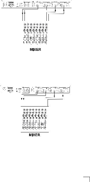
Mixer - Mono In/Stereo Out Setup
Aux |
|
Return 1 |
Return 2 |
This setup is the most commonly used configuration in both live and studio applications. A single input source is fed into the MX300, processed, and output as a stereo
8
|
MX300 |
|
Connecting the MX300 |
|
|
||||
|
|
|
signal. The Input Source must be set to Anlg Mono L in the System menu (described on page 30). This setup is ideal for programs using Cascade, Parallel, and Stereo routings (see page 16 for more information about routings).
Mixer - Dual Mono In/Stereo Out Setup
Aux |
|
|
Return 1 |
Return 2 |
Send 2 |
This setup lets the MX300 act as two effects processors. Separate input sources are fed into the MX300 and processed independently with different effects, then output as a mixed stereo signal. The Input Source must be set to Anlg Stereo in the System menu (described on page 30). This setup is ideal for programs using the Mono Split routing (see page 16 for more information about routings).
Mixer - Dual Mono In/Out Setup
Aux |
|
|
Return 1 |
Return 2 |
Send 2 |
This setup lets the MX300 act as two effects processors. Separate input sources are fed into the MX300 and processed independently with different effects, then output as separate mono signals. The Input Source must be set to Anlg Stereo in the
System menu (described on page 30). This setup is ideal for programs using the Mono Split routing (see page 16 for more information about routings).
9

Connecting the MX300
Guitar - Effects Loop Setup
Effects |
|
|
|
Effects |
|||
Return |
|
|
|
Send |
|||
|
|
|
|
|
|
|
|
|
|
|
|
|
|
|
|
|
|
|
|
|
|
|
|
|
|
|
|
|
|
|
|
This setup is optimized for use within a guitar amplifier effects loop system. A single input source is fed into the MX300 and output as a mono signal. The Input Source must be set to Anlg Mono L in the System menu (described on page 30). This setup is ideal for programs using Cascade, Parallel, and Stereo routings (see page 16 for more information about routings).
Instrument - In Line Setup
Stereo
Line Input
This setup allows a line level instrument such as an electronic keyboard to be connected directly to the MX300. Connect the outputs of the line level instrument to the MX300 inputs and connect the MX300 outputs to the input channels of a mixer, or the inputs of a powered speaker system. The Input Source must be set to Anlg Stereo in
10
 Loading...