


DD-8
DD-8 Power Amplier
User Guide
143120-1 - 5/11
DD-8 Power Ampliers
Operation Manual2
Important Safety InStructIonS
1. Read these instructions.
2. Keep these instructions.
3. Heed all warnings.
4. Follow all instructions.
5. Do not use this apparatus near water.
6. Clean only with a dry cloth.
7. Do not block any ventilation openings. Install in accordance
with the manufacturer’s instructions.
8. Do not install near any heat sources such as radiators, heat
registers, stoves, or other apparatus (including ampliers) that
produce heat.
9. Do not defeat the safety purpose of the polarized or grounding-
type plug. A polarized plug has two blades with one wider than
the other. A grounding-type plug has two blades and a third
grounding prong. The wide blade or the third prong is provided
for your safety. If the provided plug does not t into your outlet,
consult an electrician for replacement of the obsolete outlet.
10. Protect the power cord from being walked on or pinched,
particularly at plugs, convenience receptacles, and the point
where they exit from the apparatus.
11. Only use attachments/accessories specified by the
manufacturer.
12. Use only with a cart, stand, tripod, bracket, or
table specified by the manufacturer, or sold with the
apparatus. When a cart is used, use caution when
moving the cart/apparatus combination to avoid injury
from tip-over.
13. Unplug this apparatus during lightning storms or when unused
for long periods of time.
14. Refer all servicing to qualied service personnel. Servicing is
required when the apparatus has been damaged in any way,
such as power-supply cord or plug is damaged, liquid has been
spilled or objects have fallen into the apparatus, the apparatus
has been exposed to rain or moisture, does not operate
normally, or has been dropped.
15. Use the mains plug to disconnect the apparatus from the mains.
16. WARNING: TO REDUCE THE RISK OF FIRE OR ELECTRIC SHOCK,
DO NOT EXPOSE THIS APPARATUS TO RAIN OR MOISTURE.
17. DO NOT EXPOSE THIS EQUIPMENT TO DRIPPING OR
SPLASHING AND ENSURE THAT NO OBJECTS FILLED
WITH LIQUIDS, SUCH AS VASES, ARE PLACED ON THE
EQUIPMENT.
18. THE MAINS PLUG OF THE POWER SUPPLY CORD SHALL REMAIN
READILY OPERABLE.
TO PREVENT ELECTRIC SHOCK DO NOT REMOVE TOP OR
BOTTOM COVERS. NO USER SERVICEABLE PARTS INSIDE.
REFER SERVICING TO QUALIFIED SERVICE PERSONNEL.
TO COMPLETELY DISCONNECT THIS EQUIPMENT FROM
THE AC MAINS, DISCONNECT THE POWER SUPPLY CORD
PLUG FROM THE AC RECEPTACLE. THE MAINS PLUG OF
THE POWER SUPPLY CORD SHALL REMAIN READILY
OPERABLE.
WATCH FOR THESE SYMBOLS:
The lightning bolt triangle is used to alert the user to the
risk of electric shock.
The exclamation point triangle is used to alert the user to
important operating or maintenance instructions.
IMPORTANT
DD-8 ampliers require Class 2 output wiring.
MAGNETIC FIELD
CAUTION! Do not locate sensitive high-gain equipment such
as preamplifiers or tape decks directly above or below the unit.
Because this amplifier has a high power density, it has a strong
magnetic eld which can induce hum into unshielded devices that
are located nearby. The eld is strongest just above and below the
unit.
If an equipment rack is used, we recommend locating the
amplier(s) in the bottom of the rack and the preamplier or other
sensitive equipment at the top.

DD-8 Power Ampliers
Operation Manual 3
DECLARATION OF CONFORMITY
Issued By: Harman International.
1718 W. Mishawaka Rd.
Elkhart, IN 46517 U.S.A.
FOR FIELD SERVICE
QUESTIONS CALL: 1 800 691 4171
European Representative’s Name and Address:
Andy Baker
Cranborne House, Cranborne Rd.
Potters Bar, Hertfordshire EN6 3JN
United Kingdom
Equipment Type: Power amplier. Family Name: DD Series. Model Names: DD-8
EMC Standards:
EN 55022:2006 + A1:2007 Limits and Methods of Measurement of Radio Disturbance Characteristics of ITE: Radiated, Class B Limits;
Conducted, Class B
EN 61000-4-2:2008 Ed 2.0 Electrostatic Discharge Immunity (Environment E2-Criteria B, 4k V Contact, 8k V Air Discharge)
EN 61000-4-3:2010 Ed 3.2 Radiated, Radio-Frequency, EMC Immunity (Environment E2, Criteria A)
EN 61000-4-4:2007 Electrical Fast Transient/Burst Immunity (Criteria B)
EN 61000-4-5:2006 Surge Immunity (Criteria B)
EN 61000-4-6:2006 Immunity to Conducted Disturbances Induced by Radio-Frequency Fields (Criteria A)
EN 61000-4-11:2004 Voltage Dips, Short Interruptions and Voltage Variation
EN 61000-3-2:2005 + A1:2008 Limits for Harmonic Current Emissions (equipment input current less than or equal to 16A.
EN 61000-3-3:2008 Limitation of Voltage Fluctuations and Flicker in Low-Voltage Supply systems Rated Current less than or equal to 16A
Safety Standard:
IEC 60065:2001 Ed 7 +A1:2005 Safety Requirements – Audio, Video, and Similar Electronic Apparatus
I certify that the product identied above conforms to the requirements of the EMC Council Directive 2004/108/EC and the Low Voltage
Directive 2006/95/EC.
Signed ______________________
Bob Chadderdon
Title: Director of Engineering Date of Issue: June 1, 2011
Obtaining Other Language Versions:
To obtain information in another language about the use of this product, please contact your local Lexicon
Distributor. If you need assistance locating your local distributor, please contact Lexicon at 888-691-4171.
This manual does not include all of the details of design, production, or variations of the equipment. Nor does
it cover every possible situation which may arise during installation, operation or maintenance.
The information provided in this manual was deemed accurate as of the publication date. However, updates to
this information may have occurred. To obtain the latest version of this manual, please visit the Lexicon website
at www.lexicon.com.
Trademark Notice:
Lexicon and the Lexicon logo are registered trademarks of Harman International Industries, Inc.
Later versions of this manual and additional information about this product may be available at the Lexicon
website at www.lexicon.com.
©2011 by Harman International,
1718 W. Mishawaka Rd., Elkhart, Indiana 46517 U.S.A. Telephone: 800-691-4171.
DD-8 Power Ampliers
Operation Manual4
DocumentatIon conventIonS
This document contains general safety, installation, and operating instructions for the DD-8 Power
Amplier. It is important to read this user guide before attempting to use this product. Pay particular
attention to safety instructions.
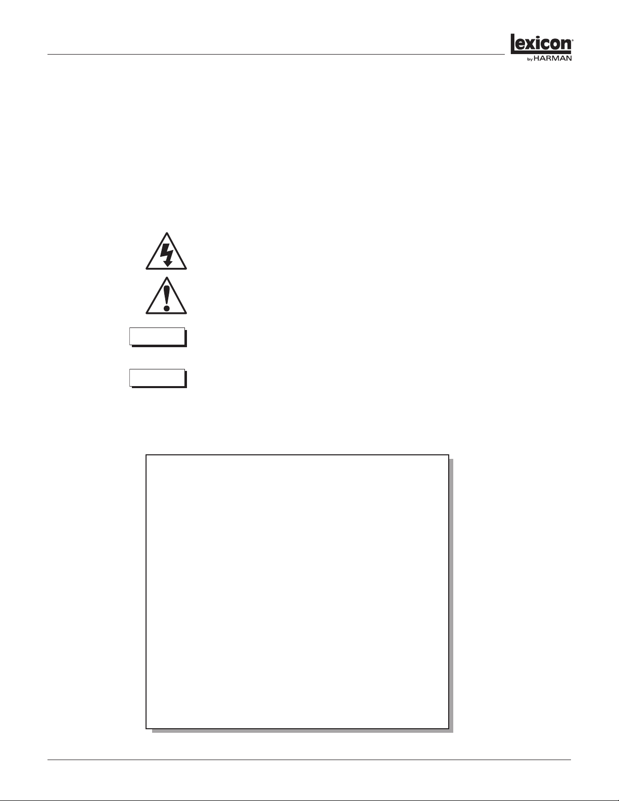
The following symbols are used in this document:
Appears on the component to indicate the presence of uninsulated, dangerous voltage
inside the enclosure – voltage that may be sucient to constitute a risk of shock.
Appears on the component to indicate important operating and maintenance
instructions in the accompanying literature.
Calls attention to a procedure, practice, condition or the like that, if not correctly
performed or adhered to, could result in injury or death.
Calls attention to a procedure, practice, condition or the like that, if not correctly performed
or adhered to, could result in damage to or destruction of part or all of the product.
Calls attention to information that is essential to highlight.
CAUTION
WAR NING
NOTE:
FCC COMPLIANCE NOTICE
This device complies with part 15 of the FCC rules. Operation is subject to the
following two conditions: (1) This device may not cause harmful interference, and (2)
this device must accept any interference received, including interference that may
cause undesired operation.
CAUTION: Changes or modifications not expressly approved by the party
responsible for compliance could void the user’s authority to operate the equipment.
NOTE: This equipment has been tested and found to comply with the limits for a
Class B digital device, pursuant to part 15 of the FCC Rules. These limits are designed
to provide reasonable protection against harmful interference in a residential
installation. This equipment generates, uses, and can radiate radio frequency energy
and, if not installed and used in accordance with the instruction manual, may cause
harmful interference to radio communications. However, there is no guarantee that
interference will not occur in a particular installation. If this equipment does cause
harmful interference to radio or television reception, which can be determined
by turning the equipment o and on, the user is encouraged to try to correct the
interference by one or more of the following measures:
• Reorient or relocate the receiving antenna.
• Increase the separation between the equipment and receiver.
• Connect the equipment into an outlet on a circuit dierent from that to which
the receiver is connected.
• Consult the dealer or an experienced radio/TV technician for help.

DD-8 Power Ampliers
Operation Manual 5
GettInG StarteD
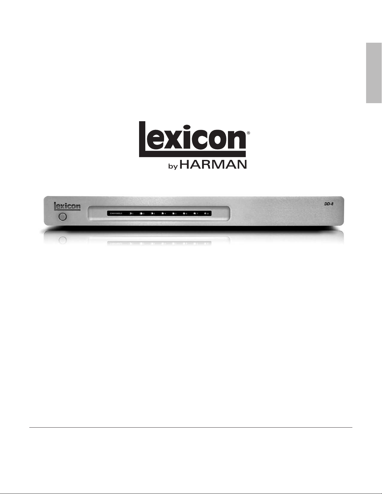
Thank you for purchasing your new Lexicon DD-8 Multi-room Amplier. The DD-8 features patented
DriveCore™ technology, delivering unprecedented levels of power from an amazingly small and
lightweight product. DriveCore takes more than 500 discrete components typically found in a
switching amplier and fuses them onto a single silicon chip about the size of a dime. Coupled with
a power supply, this chip is capable of generating big output levels into a wide variety of speaker
loads giving you the exibility to power almost any speaker from small in-ceilings to large in-room
oorstanding models.
In order to receive the maximum peak performance from your Lexicon amplier, please take a few
minutes and completely read this manual. This important information will help you make certain that
your DD-8 is properly congured for operation with the rest of the equipment in your system.
Highlights
P Multi-patented DriveCore™ amplier technology
P 8-channels each with 125W into 8-ohms, all channels driven
P Four stereo, Eight mono, or any combination stereo/mono channel conguration
P Local/Bus RCA input selection for single or multi-zone conguration
P Stereo/Mono selection and independent channel output level controls
P 12V trigger input/output and signal-sensing channel inputs
P Power Save low-power consumption standby mode (less than 0.5W)
P Front panel standby power switch with indicator LED
P Front panel channel status indicator LED’s
P Short-circuit and thermal protection circuitry
P High-eciency, quiet convection-cooled design
P Lightweight chassis only one rack space (1U) high
DD-8 Power Ampliers
Operation Manual6
Installation Considerations
To ensure optimal performance, pay particular attention to the instructions below and to other
precautions that appear throughout this user guide.
DO install the DD-8 on a solid, at, level surface such as a table or shelf. The DD-8 can also be installed
in a standard 19-inch equipment rack using the rack-mount ears included with the product.
DO select a dry, well-ventilated location out of direct sunlight.
DO NOT install the DD-8 on a surface that is unstable or unable to support all four feet.
DO NOT expose the DD-8 to high temperatures, humidity, steam, smoke, dampness or excessive dust.
Avoid installing the amplier near radiators and other heat-producing appliances.
DO NOT install the DD-8 near unshielded TV or FM antennas, cable TV decoders, or other RF-emitting
devices that might cause interference.
DO NOT place the DD-8 on a thick rug or carpet, or cover the ventilation holes in the chassis, as this
might prevent proper cooling.
DO NOT place the DD-8 on a windowsill or any location exposed to direct sunlight.
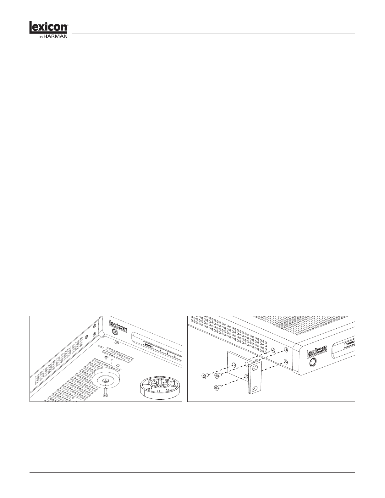
Installation Options
The DD-8 is shipped without feet or rack ears installed. Both are included in the packaging and you
will need to install one or the other depending upon the type of installation/mounting required. If the
DD-8 is to be placed on a shelf or audio furniture, you will need to attach the four plastic feet to the
bottom of the amplier using a #2 Philips screwdriver and the included hardware. (See Figure 1) If the
DD-8 is be mounted into an equipment rack, you will need to attach the two metal rack ears to the left
and right sides of the amplier using the included T-10 Torx key. (See Figure 2)
NOTE: If multiple DD-8’s are to be rack mounted together, it is acceptable to “at stack”
them one atop the other in adjacent rack spaces without additional ventilation spaces
left in between them. However, in some installations or in heavy usage scenarios where
multiple channels are consistently driven at high outputs for long periods of time, it might
be necessary to leave one empty rack space between the ampliers in order to assist with
heat dissipation and prevent thermal protection due to overheating.
GettInG StarteD
Figure 1. Feet Installati on Figure 2. Rack Ears Instal lation
DD-8 Power Ampliers
Operation Manual 7
BaSIc operatIon
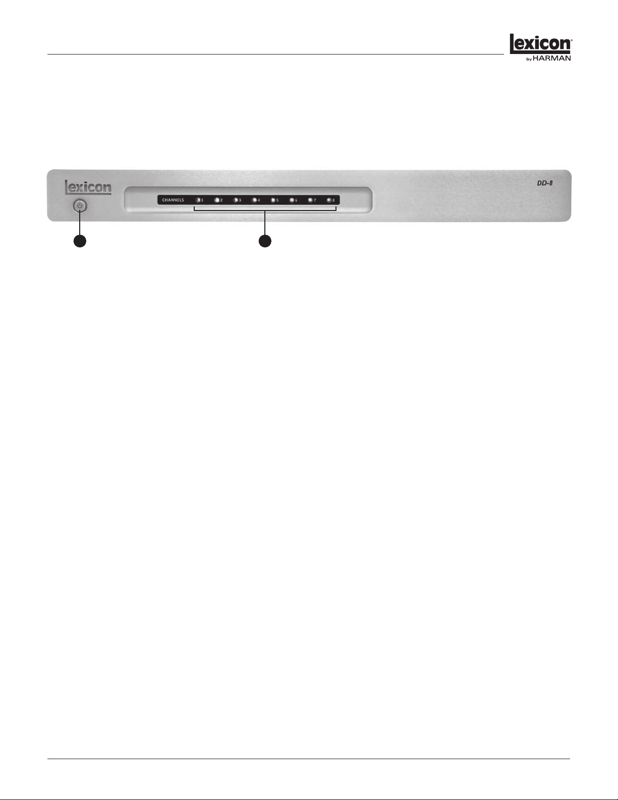
Front Panel
1. Standby Button
Activates and deactivates standby mode when the DD-8 amplier is connected to AC power.
When the DD-8 is connected to AC power, the standby button LED will glow RED indicating that the
unit is in the standby mode. In this state, the power amplier section is not activated and the unit
consumes minimal AC power. Pressing the standby button from this state will activate the power
amplier section and the standby button LED will glow BLUE indicating that the DD-8 is powered on.
NOTE: When the status of the DD-8 changes or is powered up from standby mode, there
may be a delay in audio output and relay clicks may be audible. This is normal operation.
NOTE: If the trigger input is used on the DD-8, it will override the standby button operation.
2. Channel Status Indicator LED’s
Indicates the status of each of the eight amplier channels when the DD-8 is active.
When a channel is active, its LED indicator will glow BLUE. If the channel is in standby, the LED will be
o. If a channel has a fault, the LED will blink BLUE indicating the presence of a short or some other
problem related to that channel. (See the troubleshooting section for more information.)
1 2
DD-8 Power Ampliers
Operation Manual8
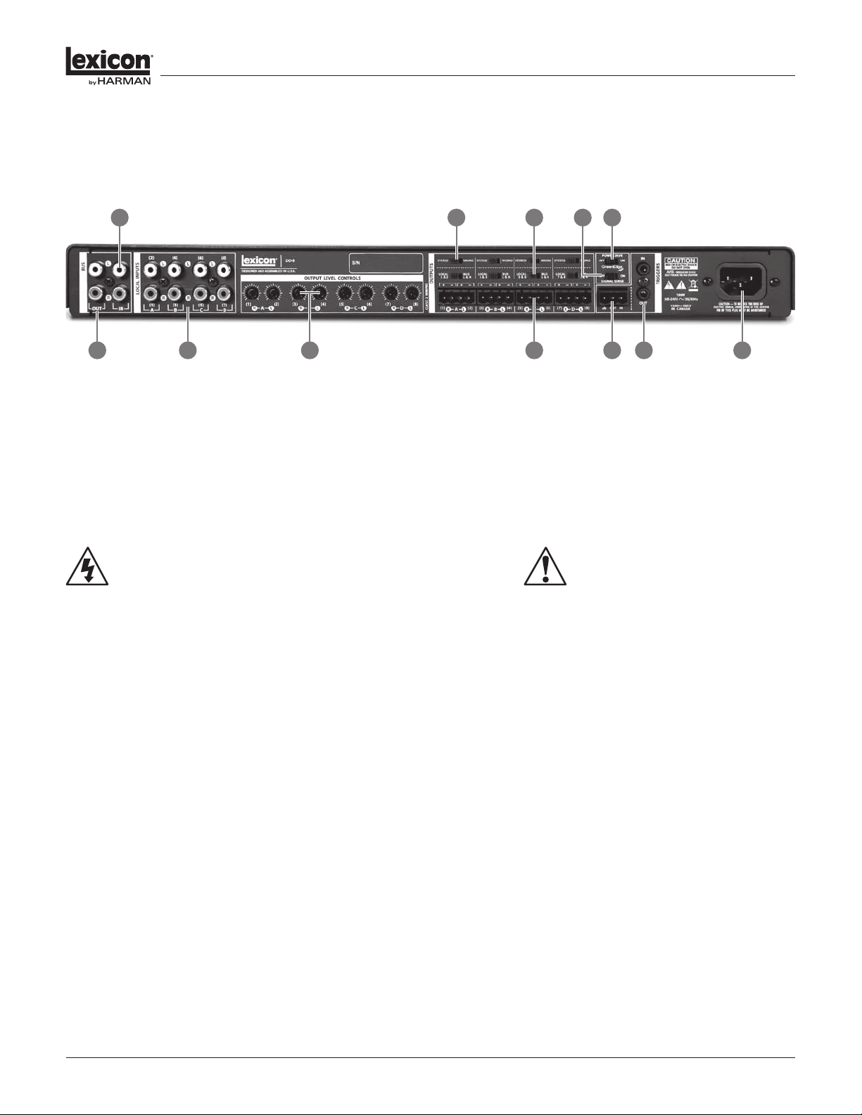
Back Panel
1. Bus Output
Provides a line-level RCA connector loop/passthru output for connecting multiple DD-8 ampliers in a
system utilizing a single bus input signal.
If the DD-8 is used as a single zone amplier and the input signal is connected via the Bus Input, that
signal can be output via this pair of RCA connectors to additional DD-8 ampliers connected in the
same manner.
NOTE: The number of DD-8 ampliers that can be connected in this manner is limited by the
output voltage of the signal source device driving the bus input as it must support the total
impedance of all of the bussed devices.
2. Bus Input
Provides a line-level RCA connector input to simultaneously feed all speaker output channels utilizing
a single bus input signal.
When the DD-8 is used as a single zone amplier, all channels can be driven using only the bus input
without the need for connection to each channel’s local input individually. If the bus input is used with
the DD-8 congured for stereo operation, the Left input signal will be routed to all four Left speaker
outputs and the Right input signal will be routed to all four Right speaker outputs.
If the bus input is used with the DD-8 congured for all mono operation, either the Left or Right Bus
Input RCA connector can be used to feed all eight speaker outputs. (See the section on “Stereo/Mono
Selection” for more information.) In this case, using only one input connector will attenuate the gain
by 6dB. A “Y-adaptor” RCA cable can be used at the input to maintain full gain if desired.
BaSIc operatIon
WARNING: Do not connect the outputs
of one channel to the outputs of other
channels or to other ampliers.
CAUTION: Never make or break connections
to the DD-8 unless the DD-8 and all
associated components are powered o!
2
1 3 4 7 1110 10
6 95 8
1. Bus Output
2. Bus Input
3. Local Inputs
4. Output Level Controls
5. Stereo/Mono Selection
6. Local/Bus Selection
7. Speaker Outputs
8. Signal Sense On/O
9. Power Save On/O
10. Trigger In/Out
11. AC Main Power Connector

DD-8 Power Ampliers
Operation Manual 9
BaSIc operatIon
3. Local Inputs
Provides a line-level RCA connector input to feed a corresponding speaker-level output channel.
When the DD-8 is used as a multi-zone amplier, each channel can be provided with a dedicated input
signal. The signals from this input will only be available on the corresponding speaker-level output.
Local inputs are grouped and identied in pairs with the labels A, B, C and D and channel numbers 1-8
on the rear panel of the DD-8. These labels can be utilized to easily identify corresponding controls
and connections for selecting desired output congurations.
4. Output Level Controls
Provides speaker-level attenuation for each output channel.
The output level controls function as attenuators for each channel and can be used to level-match
speakers in an installation. The center detent is the default position that will be appropriate for most
speakers with +13dB or -76dB of adjustment from default available as needed. These controls are
labeled in pairs A, B, C and D and with channel numbers 1-8 to easily identify which speaker-level
output is being adjusted.
5. Stereo/Mono Selection
Selects between Stereo and Mono output conguration for each group of speaker output pairs.
When using the DD-8 in standard stereo operation, select the Stereo position. In this mode, the
Left and Right stereo input signals remain intact and are output at the corresponding left and right
speaker connection. The DD-8 provides connectivity for four stereo pair of loudspeakers (A, B, C and
D) when congured in Stereo mode.
It is possible to combine a stereo bus or local input signal onto two single output channels by
selecting the Mono position for that channel pair. This mode is useful for instances where two
normally stereo speakers are located far apart and it is desirable to send a combined left and right
channel signal to both speakers simultaneously in order to maintain optimal delity.
If desired, the DD-8 can be utilized in all mono operation. In this mode, all eight channels can be
used independently with either a single mono bus input signal or eight independent mono local
input signals. As notated in the bus and local input descriptions, using only one input connector will
attenuate the gain by 6dB. A “Y-adaptor” RCA cable can be used at the input to maintain full gain if
desired.
6. Local/Bus Selection
Selects between Local and Bus inputs for each group of speaker output pairs.
The Local/Bus input selection provides the ability to easily congure the DD-8 either as a single-zone
or multi-zone amplier. The speaker outputs are grouped in pairs A, B, C and D (channels 1-8) with a
switch for each pair. For example, selecting the Bus input for speaker output pair A (channels 1 and
2) will route the input signal from the Bus input to speaker output pair A. Selecting the Local input
for speaker output pair A (channels 1 and 2) will route the input signal from the Local input pair A
(channels 1 and 2) to speaker output pair A.

DD-8 Power Ampliers
Operation Manual10
BaSIc operatIon
7. Speaker Outputs
Provides connection for up to four pair of stereo speakers (eight speakers total) to the DD-8.
Connection to speakers is provided via phoenix-type connectors that accept bare wire terminations.
The connectors are grouped in pairs with one connector each for pair A, B, C and D. Each pair
consists of four wire terminations: positive (+) and negative (–) for the Left channel and positive
(+) and negative (–) for the Right channel. To attach speaker cables to the phoenix connector, strip
approximately ¼” of insulation o of the end of the positive and negative leads of the cable and
insert the bare ends into the corresponding position of the phoenix connector, tightening the screw
terminals on top to secure the termination. Repeat this procedure for each speaker.
NOTE: It is recommended to use 16-gauge or larger speaker wire in order to ensure low-
impedance connections between the amplier and speakers. Be sure to observe correct
polarity when making connections to speakers: Positive (+) leads to the Positive (+) terminals
and Negative (–) leads to the Negative (–) terminals.
8. Power Save On/O
Enables the extreme low-power automatic standby mode of the DD-8.
The DD-8 is a highly ecient design with lower-than-average power consumption at standby, idle
and in normal operation mode. The Power Save mode can be enabled to lower standby power
consumption even further by disabling all circuitry except that required for the front panel standby
button. If the Power Save switch is set to the On position, the DD-8 will automatically revert to standby
and enter this extreme low-power state after one hour without signal present at any of the inputs.
If the Power Save switch is in the O position and the DD-8 is active, it will remain on indenitely
regardless of the presence of input signals until the amplier is put into standby mode via the front
panel standby switch.
NOTE: The Power Save function can only be used when operating the DD-8 from the front
panel standby button. If a trigger input is being used, it will override the Power Save function.
9. Signal Sense On/O
Enables the audio Signal Sense circuitry for the Bus and Local inputs.
The Signal Sense circuitry allows the DD-8 to activate a channel (1, 2, 3, 4, 5, 6, 7 or 8) when an audio
signal is detected at the corresponding input and deactivate a channel (1, 2, 3, 4, 5, 6, 7 or 8) when no
audio signal has been present for 30 minutes. When the DD-8 is powered on and the Signal Sense
switch is set to the On position, amplier channels with signal present will be active. Channels without
signals present will remain switched o until signals are detected. In this mode, power consumption is
lowered by switching o idle channels and audio performance is improved by eliminating crosstalk on
adjacent unused channels. In cases where Signal Sense is On and no audio signals are present on any
channels for more than 30 minutes, all channels will be switched o and only the front panel standby
button will glow blue while the DD-8 continues to monitor all inputs for a signal.
CAUTION: The speaker outputs on the DD-8 are
balanced (dierential) and should not be connected to
any equipment that grounds the Negative (–) terminals.

DD-8 Power Ampliers
Operation Manual 11
BaSIc operatIon
NOTE: It is possible to have a situation where Signal Sense cannot function if the Power
Save feature is also used and has been activated. For example, Signal Sense will deactivate
channels without signals after 30 minutes. If all channels are deactivated, Power Save will
be enabled after an additional 30 minutes of no signal. During that additional 30 minutes,
Signal Sense will continue to function and will activate any channels that receive an
incoming audio signal. Once the Power Save standby mode has been enabled, Signal Sense
will not be able to function requiring the DD-8 to be turned on again via the front panel
standby button.
NOTE: In some cases, audio signals with very low output may not activate the Signal Sense
circuitry in a timely manner or in some cases, not at all. This could occur with music or audio
that begins with very soft or quiet passages or with abnormally low-voltage source signals. If
the Signal Sense circuitry will not reliably activate channels within the DD-8, it is suggested
to use either the front panel standby button or trigger input control for proper operation.
10. Trigger In/Out
Provides connectivity for remote 5-15VDC trigger signals used to activate and deactivate the standby
mode of the DD-8.
The Trigger In and Out connections can be used to activate and deactivate the standby mode of
the DD-8 from devices such as remote control systems, preampliers or other external devices. The
Trigger In and Out connections are duplicated for both 1/8” (3.5mm) mono mini-plug and phoenix-
style connectors. Use the Trigger In for making connections to external control devices that will
activate and deactivate the DD-8 standby mode. The Trigger Out does not provide DC power on its
own, but can be used for making Trigger In daisy-chain connections to additional DD-8 ampliers or
other components that need to mimic the DD-8 power state.
NOTE: When a remote trigger is connected it will override the front panel standby button
operation.
To install a trigger cable:
P Power the controlling source and DD-8 amplier o.
P Connect the trigger cable to the controlling source and the DD-8 amplier.
P After the connections are made, power on the controlling source and the DD-8 amplier. After the
source unit is fully powered up, the LED power indicator on the front of the DD-8 should be lit BLUE.
P Verify the trigger is working by putting the source unit into standby mode. The DD-8 amplier after
a short delay will also go into the standby mode and the power indicator will light up RED.
P Once you have veried that the trigger cable is working, only use the source unit to power on and
o your DD-8 amplier.
WARNING: When installing the trigger cable, never have
the controlling source or DD-8 amplier powered on.
Doing so will cause the trigger device to work improperly
and could cause damage to both the source and amplier.

DD-8 Power Ampliers
Operation Manual12
BaSIc operatIon
11. AC Main Power Connector
Provides an AC power connection to the DD-8 using the supplied power cord.
After all audio and system connections have been made, connect the power cord to an AC power
source. Be sure that any device connected to the remote trigger input is powered o when connecting
the DD-8 power cord to an AC outlet.
WARNING: Do not plug the DD-8 directly into the “Switched Accessory” outlet of
another device! These outlets are intended for use with low current draw products
such as tuners, CD players, Blu-ray players and other similar devices. These outlets are
not designed to handle the high current draw of a power amplier. Using these outlets
for a power amplier is a signicant safety hazard.

DD-8 Power Ampliers
Operation Manual 13
trouBleShootInG anD maIntenance
Troubleshooting
The amplier does not power on.
1. Attempt to power on the amplier with the front panel Standby/On button.
2. Examine the power cord to ensure a good connection between the rear panel AC input
connector and the wall outlet.
3. Check the wall outlet.
The Trigger Input is connected to an external device, but the amplier does not power on and
o with the external device.
1. Verify the trigger cable is connected at both ends and verify that the trigger cable is
connected to the right device. Also re-verify the trigger installation instructions as
instructed in the Basic Operation section of this user guide.
2. Verify the trigger level of the output source device. The DD-8 accepts a range of
5-15VDC.
Source signals are present and the system is at a suitable volume level but one or more
channels are not passing audio.
1. Reduce system volume level.
2. Power the DD-8 into standby mode.
3. Check input connections.
4. Check speaker connections.
5. Allow the amplier to cool before powering it on again.
Audio sounds “thin” and is lacking proper bass response.
Check to ensure proper polarity of the speaker cables and connections.
Audio Levels dier between channels.
1. Check the level settings of the DD-8 Output Level Controls.
2. Check the settings on your preamp, processor or controller.
Audio plays and then cuts o.
Check input and speaker connections for short circuits or loose connections at the amplier
and speaker.

DD-8 Power Ampliers
Operation Manual14
trouBleShootInG anD maIntenance
A humming sound is present in the audio.
Audible hum, or a discernable low frequency noise is one of the most common problems within
audio/video systems. This problem, even when the volume is at a low level, Is usually caused by a
common problem known as a “ground loop”. A ground loop occurs when there is a dierence in
ground voltages between two or more components that are connected electrically.
In most cases, one or more of the following suggestions below will solve the hum problem.
1. If a cable TV connection is present, disconnect the cable for the wall outlet. If this
eliminates the humming sound, a ground loop isolation device is required. Contact your
dealer or cable provider for assistance.
2. Disconnect components one at a time to isolate the problem. Once the problem is
identied, make sure the associated component is properly grounded and connected to
the same electrical ground as the DD-8 amplier.
3. Turn o all components within your system and then disconnect the input cables on the
DD-8 amplier. Turn the amplier back on. If the hum disappears the fault may be with
the input cables that are being used. Make sure the cables are properly shielded or use
a cable that has better shielding. Make sure the cable is not running or laying on top of
any AC power cords.
4. Ground loop problems may also be caused by poor grounding of the electrical system
within your home or may be caused by faulty earth grounds in your home’s electrical
system. To isolate the problem, try unplugging components with three prong grounded
power cords one at a time to see if one or all are causing the problem. In the past, cold
water pipes and other utilities were often used for grounds. These items may not be
still valid because of corrosion of the existing pipes and the installation and use of PVC
piping. Please check with a licensed electrician for further evaluation.
If all else fails…
1. Contact an authorized Lexicon dealer.
2. Contact Lexicon Customer Technical Support at 888-691-4171.
Maintenance
Routine maintenance should be performed on a periodic basis. Clean the exterior surfaces of the
unit with a soft, dry, lint-free cloth. Do not use alcohol, benzene, acetone-based cleaners, or strong
commercial cleaners. Do not use a cloth made with steel wool or metal polish. If the unit is exposed to
a dusty environment, a low-pressure blower may be used to remove dust from its exterior.

DD-8 Power Ampliers
Operation Manual 15
appenDIX
Specications
Specications are subject to change without notice.
Output Power: 125W RMS per channel into 8 ohms from 20Hz – 20kHz
Frequency Response: 20Hz - 20kHz +0dB/–1.5dB
Total Harmonic Distortion (THD): Less than 0.05% at full rated power 20Hz - 20kHz
Signal-to-Noise Ratio: < –105dB below rated full power A-weighted
Crosstalk: < –70dB @ 1kHz
Input Sensitivity: 1.12 volts for 125W out into 8 ohms
Gain: 29dB
Input Impedance: 100K ohms typical
Trigger Input: 5V minimum – 15V maximum DC
Dimensions (H x W x D): 2.1” (w/ feet) / 1.7” (w/out feet) x 17.3” x 14.9”
5.4 cm (w/ feet) / 4.5cm (w/out feet) x 43.8 cm x 37.8 cm
Weight: 9.2 lbs (4.2 kg)
Power Requirements: 100 - 240VAC 50/60Hz 190W

DD-8 Power Ampliers
Operation Manual16
THIS PAGE INTENTIONALLY LEFT BLANK
DD-8 Leistungsverstärker
Benutzerhandbuch
143120-1 - 5/11
DEUTSCH

DD-8 Leistungsverstärker
Bedienungsanleitung18
DECLARATION OF CONFORMITY
Issued By: Harman International.
1718 W. Mishawaka Rd.
Elkhart, IN 46517 U.S.A.
FOR FIELD SERVICE
QUESTIONS CALL: 1 800 691 4171
European Representative’s Name and Address:
Andy Baker
Cranborne House, Cranborne Rd.
Potters Bar, Hertfordshire EN6 3JN
United Kingdom
Equipment Type: Power amplier. Family Name: DD Series. Model Names: DD-8
EMC Standards:
EN 55022:2006 + A1:2007 Limits and Methods of Measurement of Radio Disturbance Characteristics of ITE: Radiated, Class B Limits;
Conducted, Class B
EN 61000-4-2:2008 Ed 2.0 Electrostatic Discharge Immunity (Environment E2-Criteria B, 4k V Contact, 8k V Air Discharge)
EN 61000-4-3:2010 Ed 3.2 Radiated, Radio-Frequency, EMC Immunity (Environment E2, Criteria A)
EN 61000-4-4:2007 Electrical Fast Transient/Burst Immunity (Criteria B)
EN 61000-4-5:2006 Surge Immunity (Criteria B)
EN 61000-4-6:2006 Immunity to Conducted Disturbances Induced by Radio-Frequency Fields (Criteria A)
EN 61000-4-11:2004 Voltage Dips, Short Interruptions and Voltage Variation
EN 61000-3-2:2005 + A1:2008 Limits for Harmonic Current Emissions (equipment input current less than or equal to 16A.
EN 61000-3-3:2008 Limitation of Voltage Fluctuations and Flicker in Low-Voltage Supply systems Rated Current less than or equal to 16A
Safety Standard:
IEC 60065:2001 Ed 7 +A1:2005 Safety Requirements – Audio, Video, and Similar Electronic Apparatus
I certify that the product identied above conforms to the requirements of the EMC Council Directive 2004/108/EC and the Low Voltage
Directive 2006/95/EC.
Signed ______________________
Bob Chadderdon
Title: Director of Engineering Date of Issue: June 1, 2011
Versionen in anderen Sprachen:
Bedienungsanleitungen zu diesem Produkt in anderen Sprachen können Sie bei einem Lexicon-Vertriebspartner
in Ihrer Nähe anfordern. Informationen über einen Vertriebspartner in Ihrer Nähe erhalten Sie bei Lexicon unter
der Rufnummer 888-691-4171.
Dieses Handbuch enthält keine vollständige Darstellung der Bauart, Herstellung oder Produktvarianten des
Gerätes. Es deckt auch nicht jede denkbare Situation ab, die bei der Installation, dem Betrieb oder der Wartung
auftreten könnte.
Die Informationen in diesem Handbuch galten am Herausgabetag als richtig. Spätere Änderungen dieser
Informationen können jedoch nicht ausgeschlossen werden. Die neueste Version dieses Handbuches erhalten
Sie auf der Lexicon-Website unter der Adresse www.lexicon.com.
Hinweis zu Marken:
Lexicon und das Lexicon-Logo sind eingetragene Warenzeichen von Harman International Industries, Inc.
Neuere Versionen von diesem Handbuch und zusätzliche Informationen über dieses Produkt sind auf der
Lexicon-Website unter www.lexicon.com zu beziehen.
©2011 by Harman International,
1718 W. Mishawaka Rd., Elkhart, Indiana 46517 USA. Telefon: 800-691-4171.
DD-8 Leistungsverstärker
Bedienungsanleitung 19
DokumentatIonSkonventIonen
Dieses Dokument enthält allgemeine Hinweise zu Sicherheitsvorkehrungen, zur Installation
und zum Betrieb des DD-8 Leistungsverstärkers. Vor dem Gebrauch dieses Produkt sollte dieses
Benutzerhandbuch gelesen werden. Insbesondere die Sicherheitshinweise sind zu beachten.
In diesem Dokument werden die folgenden Symbole verwendet:
Dieses Symbol auf einer Komponente weist auf das Vorhandensein von nicht
isolierter, gefährlicher Spannung im Gehäuse hin. Die Spannung ist unter Umständen
ausreichend, um die Gefahr eines elektrischen Schlages zu bergen.
Dieses Symbol auf einer Komponente weist darauf hin, dass die Begleitdokumentation
wichtige Hinweise zum Betrieb und zur Wartung enthält.
Dieses Symbol macht auf ein Verfahren, eine Praxis, eine Bedingung oder Ähnliches
aufmerksam, deren Nichtbeachtung Verletzungen bis hin zum Tod nach sich ziehen
kann.
Dieses Symbol macht auf ein Verfahren, eine Praxis, eine Bedingung oder Ähnliches hin,
deren Nichtbeachtung zu Schäden am Produkt oder zur teilweisen oder vollständigen
Zerstörung des Produkts führen kann.
Dieses Symbol weist auf eine wichtige Information hin, die zu beachten ist.
HINWEIS:
FCC COMPLIANCE NOTICE
This device complies with part 15 of the FCC rules. Operation is subject to the
following two conditions: (1) This device may not cause harmful interference, and (2)
this device must accept any interference received, including interference that may
cause undesired operation.
CAUTION: Changes or modifications not expressly approved by the party
responsible for compliance could void the user’s authority to operate the equipment.
NOTE: This equipment has been tested and found to comply with the limits for a
Class B digital device, pursuant to part 15 of the FCC Rules. These limits are designed
to provide reasonable protection against harmful interference in a residential
installation. This equipment generates, uses, and can radiate radio frequency energy
and, if not installed and used in accordance with the instruction manual, may cause
harmful interference to radio communications. However, there is no guarantee that
interference will not occur in a particular installation. If this equipment does cause
harmful interference to radio or television reception, which can be determined
by turning the equipment o and on, the user is encouraged to try to correct the
interference by one or more of the following measures:
• Reorient or relocate the receiving antenna.
• Increase the separation between the equipment and receiver.
• Connect the equipment into an outlet on a circuit dierent from that to which
the receiver is connected.
• Consult the dealer or an experienced radio/TV technician for help.
ACHTUNG
WARNUNG

DD-8 Leistungsverstärker
Bedienungsanleitung20
erSte SchrItte
Herzlichen Glückwunsch zum Kauf Ihres neuen Lexicon DD-8 Mehrraumverstärkers. Der DD-8
ist mit der patentgeschützten DriveCore™ Technologie ausgestattet und bietet ein beispielloses
Maß an Leistung in einem erstaunlich kleinen und leichten Produkt. DriveCore vereinigt über 500
Einzelkomponenten, die normalerweise in einem Digitalverstärker vorkommen, auf einem einzigen
Silikonchip in der Größe einer kleinen Münze. In Verbindung mit einer Stromversorgung kann dieser
Chip eine hohe Ausgabeleistung auf einem breiten Spektrum an Lautsprecherlasten erzeugen.
So genießen Sie die Flexibilität, fast jeden Lautsprecher verstärken zu können: von kleinen, in die
Zimmerdecke eingebauten Lautsprechern bis zu großen, auf dem Boden stehenden Innenraumboxen.
Damit Sie mit Ihrem Lexicon-Verstärker eine maximale Peak-Leistung erzielen, sollten Sie sich einen
Moment Zeit nehmen und dieses Handbuch vollständig durchlesen. Darin nden Sie wichtige
Informationen, mit denen Sie sicherstellen können, dass Ihr DD-8 optimal für den Betrieb mit allen
Geräten Ihres Systems konguriert ist.
Besondere Merkmale
P Durch mehrere Patente geschützte DriveCore™ Verstärkertechnologie
P Je 8 Kanäle mit 125W an 8 Ohm, alle Kanäle betrieben
P Kongurationen mit vier Stereokanälen, acht Monokanälen oder einer beliebigen Kombination aus
Stereo- und Monokanälen
P Auswahl zwischen lokalen Cinch-Eingängen und Bus-Eingang zur Zonenkonguration
P Stereo-Mono-Auswahl und unabhängige Pegelsteuerung an den Kanalausgängen
P 12-Volt-Trigger-Ein-/Ausgang und Eingangssignalüberwachung mit Signalsensoren
P Power Save: Energiesparender Standby-Modus (unter 0,5W)
P Standby-Stromschalter mit LED-Anzeige auf der Vorderseite
P LED-Anzeigen für den Kanalstatus auf der Vorderseite
P Kurzschluss- und Wärmeschutzschalter
P Hocheziente, geräuscharme Bauart mit Konvektionskühlung
P Leichtes Gehäuse mit einer Höhe von nur einer Racketage (1U)
 Loading...