


MV-5 Processor
User Guide

IMPORTANT SAFETY INSTRUCTIONS
1.Read these instructions.
2.Keep these instructions.
3.Heed all warnings.
4.Follow all instructions.
5.Do not use this apparatus near water.
6.Clean only with a dry cloth.
7.Do not block any ventilation openings. Install in accordance with the manufacturer’s instructions.
8.Do not install near any heat sources such as radiators, heat registers, stoves, or other apparatus (including amplifiers) that produce heat.
9.Do not defeat the safety purpose of the polarized or grounding-type plug. A polarized plug has two blades with one wider than the other. A grounding-type plug has two blades and a third grounding prong. The wide blade or the third prong are provided for your safety. If the provided plug does not fit into your outlet, consult an electrician for replacement of the obsolete outlet.
10.Protect the power cord from being walked on or pinched, particularly at plugs, convenience receptacles, and the point where they exit from the apparatus.
11.Only use attachments/accessories specified by the manufacturer.
12.Use only with the cart, stand, tripod, bracket or table specified by the manufacturer, or sold with the apparatus. When a cart is used, use caution when moving the cart/apparatus combination to avoid injury from tip-over.
13.Unplug this apparatus during lightning storms or when unused for long periods of time.
14.Refer all servicing to qualified service personnel. Servicing is required when the apparatus has been damaged in any way, such as when a power supply cord or plug is damaged, liquid has been spilled or objects have fallen into the apparatus, the apparatus has been exposed to rain or moisture, does not operate normally, or has been dropped.
15.Do not expose this apparatus to dripping or splashing and ensure that no objects filled with liquids, such as vases, are placed on the apparatus.
16.To completely disconnect this apparatus from the AC Mains, disconnect the power supply cord plug from the AC receptacle.
17.The MAINS cord is intended to be the safety disconnect device for this apparatus and shall remain readily operable at all times.
18.Do not expose batteries to excessive heat, such as sunshine, fire, or the like.
19.This product shall be connected to a MAINS socket outlet with a protective earthing connection.
This equipment has been tested and found to comply with the limits for a Class B digital device, pursuant to Part 15 of FCC Rules. These limits are designed to provide reasonable protection against harmful interference in a residential installation. This equipment generates, uses, and radiates radio frequency energy and, if not installed and used in accordance with the instructions, may cause harmful interference to radio or television reception, which can be determined by turning the equipment off and on. The user is encouraged to try to correct the interference by one or more of the following measures:
•Re-orient or relocate the receiving antenna.
•Increase the separation between the equipment and the receiver.
•Connect the equipment into an outlet on a circuit different from that to which the receiver is connected.
•Consult the dealer or an experienced radio/ television technician for help.
This device complies with part 15 of the FCC Rules. Operation is subject to the following two conditions: (1) this device may not cause harmful interference, and (2) this device must accept interference received, including interference that may cause undesired operation.
CAUTION
Changes or modifications not expressly approved by the party responsible for compliance could void the user's authority to operate the equipment.
Canada
This Class B digital apparatus complies with Canadian ICES-003.
Cet appareil numérique de la classe B est conforme à la norme NMB-003 du Canada.
WARNING 

To reduce the risk of fire or electric shock, do not expose this apparatus to rain or moisture.
The lightning flash with arrowhead symbol, within an equilateral triangle, is intended to alert the user to the presence of uninsulated “dangerous voltage” within the product’s enclosure that may be of sufficient magnitude to constitute a risk of electric shock to persons.
The exclamation point within an equilateral triangle is intended to alert the user to the presence of important operating and maintenance (servicing) instructions in the literature accompanying the product.

Lexicon Inc.
3 Oak Park Drive
Bedford, MA 01730-1413 USA Tel 781-280-0300
Fax 781-280-0490 www.lexicon.com
Customer Service
Telephone: 781-280-0300
Sales Fax: 781-280-0495
Service Fax: 781-280-0499
Part No. 070-18137 | Rev 0 | 07/07
Lexicon, “Logic 7”, and the L7 logo are registered trademarks of Harman International Industries, Inc.
Manufactured under license from Dolby Laboratories. “Dolby”, “Pro Logic”, and the double-D symbol are trademarks of Dolby Laboratories.
“DTS” and “DTS-ES | Neo:6” are registered trademarks of DTS, Inc. and “96/24” is a trademark of DTS, Inc. “Faroudja” and “DCDi by Faroudja” are trademarks of Genesis Microchip, Inc.
“HD-DVD” is a trademark of the DVD Format/Logo Licensing Corporation (DVD FLLC).
“HDMI”, the HDMI logo, and “High-Definition Multimedia Interface” are trademarks or registered trademarks of HDMI Licensing LLC.
“iPod” and “iTunes” are trademarks of Apple Computer, Inc. “SACD” is a trademark of Sony Electronics, Inc.
“Windows” is a trademark of Microsoft, Inc.
“DLP” and “Digital Light Processing” are trademarks of Texas Instruments, Inc.
Other company and product names may be trademarks of the respective companies with which they are associated.
© 2007 Harman Specialty Group and Harman International Industries, Incorporated. All rights reserved. Harman Specialty Group is a wholly-owned company of Harman International, Inc.
This document should not be construed as a commitment on the part of Harman Specialty Group. The information it contains is subject to change without notice. Harman Specialty Group assumes no responsibility for errors that may appear within this document.

Introduction |
Lexicon |
DOCUMENTATION CONVENTIONS
This document contains general safety, installation and operation instructions for the MV-5 Processor. It is important to read this user guide before attempting to use the product. Pay particular attention to safety instructions.
Note: This manual is not intended as a general reference guide for home theater systems. If you’re uncertain how to proceed in setting up or maintaining your system, seek the advice of a professional installer or ask your dealer for their recommendations.
All graphics of the product are included for reference only and may not completely reflect the physical product that is shipped.
The following symbols are used in the document:
Appears on the component to indicate the presence of uninsulated, dangerous voltage inside the enclosure – voltage that may be sufficient to constitute a risk of shock.
Appears on the component to indicate important operating and maintenance instructions in the accompanying literature.
WARNING
Calls attention to a procedure, practice, condition or the like that, if not correctly performed or adhered to, could result in injury or death.
CAUTION! Calls attention to a procedure, practice, condition or the like that, if not correctly
performed or adhered to, could result in damage or destruction to part or all of the product.
Note: Calls attention to information that is essential to highlight.
ii

MV-5 |
Introduction |
Table of Contents
Documentation Conventions........................................................ ii
Getting Started
About the MV-5 ........................................................................ |
1-2 |
Product Registration .................................................................. |
1-2 |
Highlights ................................................................................. |
1-2 |
What’s in the Box...................................................................... |
1-3 |
Available Options ...................................................................... |
1-3 |
D-1 iPod Docking Station Option .......................................... |
1-3 |
RF-1 Receiver Option ............................................................. |
1-3 |
Installation Considerations......................................................... |
1-4 |
Remote Control Battery Installation ........................................... |
1-4 |
Basic Operation
Front Panel Overview ................................................................ |
2-2 |
Rear Panel Overview.................................................................. |
2-5 |
PC & Dock Overview................................................................. |
2-8 |
Remote Control Overview ......................................................... |
2-8 |
Operation Considerations ...................................................... |
2-8 |
MV-5 Menu Overview ........................................................... |
2-9 |
Menu Navigation .................................................................. |
2-9 |
........................................................................................... |
2-10 |
Remote Control Buttons ...................................................... |
2-10 |
Menu Options ..................................................................... |
2-11 |
Menu Item Selection ........................................................... |
2-11 |
Remote Control Light Button .............................................. |
2-11 |
Command Matrix ............................................................... |
2-11 |
Setup
Setup ........................................................................................ |
3-2 |
Display Setup ............................................................................ |
3-3 |
Speaker/EQ Setup ..................................................................... |
3-5 |
Manual .................................................................................. |
3-6 |
Semi Autocal.......................................................................... |
3-6 |
Full Autocal ............................................................................ |
3-6 |
Manual Speaker Setup............................................................... |
3-8 |
Speakers Menu ..................................................................... |
3-9 |
Speaker Distances Menu ..................................................... |
3-10 |
Output Levels Menu ............................................................ |
3-11 |
Input Setup ............................................................................. |
3-13 |
Advanced Video .................................................................. |
3-19 |
Listening Modes...................................................................... |
3-22 |
Selecting a Listening Mode ................................................. |
3-22 |
DTS + Dolby Listening Modes ............................................. |
3-22 |
Available Listening Modes ................................................... |
3-23 |
Listening Mode Descriptions ............................................... |
3-26 |
5.1-channel & 7.1-channel Direct Inputs ............................. |
3-28 |
DTS & Dolby Status Displays ............................................... |
3-28 |
Surround Configuration .......................................................... |
3-29 |
Dolby Configuration ............................................................... |
3-31 |
Mute Levels............................................................................. |
3-32 |
Power On Settings .................................................................. |
3-32 |
Audio Controls & Video Status
Audio Controls .......................................................................... |
4-2 |
Video Status .............................................................................. |
4-4 |
PC & Dock Controls
PC & Dock Overview................................................................. |
5-2 |
PC Controls............................................................................... |
5-2 |
Setting Up to Play ................................................................. |
5-2 |
Playing PC Media .................................................................. |
5-3 |
Dock Functionality .................................................................... |
5-4 |
Connecting the Dock to the MV-5 ........................................ |
5-4 |
iii

Introduction |
Lexicon |
Selecting the Correct iPod Insert ............................................ |
5-4 |
Docking the iPod ................................................................... |
5-5 |
Dock 2-line Display Characteristics ........................................ |
5-5 |
Controlling the iPod with the MV-5 ....................................... |
5-6 |
Charging the iPod ................................................................. |
5-6 |
Removing the iPod ................................................................ |
5-6 |
Zone 2 iPod Controls ............................................................. |
5-7 |
Troubleshooting & Maintenance
Troubleshooting ........................................................................ |
6-2 |
MV-5 Error Messages ................................................................. |
6-7 |
Video Error Messages ............................................................. |
6-7 |
Autocal Error Messages .......................................................... |
6-8 |
Video Resolutions Table ........................................................... |
6-10 |
Routine Maintenance............................................................... |
6-12 |
Restoring Factory Default Settings ........................................... |
6-12 |
Appendix A
Specifications............................................................................. |
A-2 |
Declaration of Conformity ......................................................... |
A-4 |
Appendix B
Main Menu: Audio Controls ...................................................... |
B-2 |
Main Menu: Video Status .......................................................... |
B-2 |
Main Menu: Setup..................................................................... |
B-3 |
Setup Menu: Display Setup ................................................... |
B-4 |
Setup Menu: Surround Config ............................................... |
B-4 |
Setup Menu: Speaker/EQ Setup ............................................. |
B-5 |
Setup Menu: Input Setup ...................................................... |
B-6 |
Appendix C
Remote Control Programming.................................................. |
C-2 |
Remote Control Light Button ................................................. |
C-2 |
Transmitting Icon .................................................................. |
C-2 |
Setting Up the Remote Control ............................................. |
C-3 |
Lock Feature .......................................................................... |
C-6 |
Advanced Customizing Tools ................................................ |
C-6 |
Erasing Commands ............................................................. |
C-13 |
Restoring Factory Default Settings ....................................... |
C-14 |
Optional RF-1 Receiver ........................................................... |
C-14 |
Using the 3-Digit Code Library ............................................... |
C-15 |
3-Digit Pre-programmed Codes ........................................... |
C-15 |
Appendix D
Installation Worksheet ............................................................ |
D-2 |
3-Digit Pre-programmed Codes Worksheet .............................. |
D-6 |
Index
iv

1
Getting Started
About the MV-5 ......................................................................... |
1-2 |
Product Registration ................................................................... |
1-2 |
Highlights .................................................................................. |
1-2 |
What’s in the Box ....................................................................... |
1-3 |
Available Options ....................................................................... |
1-3 |
D-1 iPod Docking Station.......................................................................... |
1-3 |
RF-1 Receiver............................................................................................. |
1-3 |
Installation Considerations.......................................................... |
1-4 |
Remote Control Battery Installation ............................................ |
1-4 |

Getting Started |
Lexicon |
ABOUT THE MV-5
Thank you for purchasing the MV-5 Processor, a multi-faceted audio and video preamplifier with built-in processing. In addition, the MV-5 can accommodate a pair of HDMI source devices and can connect directly to a PC via USB, enabling the control and playback of streaming audio files. With the optional dock accessory, iPod owners can even connect and play their iPod through the MV-5.
The MV-5 is designed to serve as the control center for your home theater system. A landmark product for Lexicon, the MV-5 offers capabilities never before offered as well as breaking ground with several brand new features. The MV-5 represents a new age in audio and video processing equipment from Lexicon.
We hope you enjoy your Lexicon experience!
PRODUCT REGISTRATION
Please register y our M V- 5 P ro cesso r onlin e a t www.harmanspeciatlygroup.com/registration/ within 15 days of purchase. Retain the sales receipt as proof of warranty coverage.
HIGHLIGHTS
•12 configurable inputs, 8 channels, 2 audio zones
•Logic 7 audio processing
•Automatic EQ and speaker calibration (microphone included)
•HDMI inputs and output
•Faroudja® video processing
•RS-232 control, rear panel IR input, 2 trigger outputs
•7.1-channel analog input array
•Universal pre-programmed and learning remote control
•PC-compatible media player support via USB connector
•iPod support (with optional accessory
•RF remote control (with optional accessory)
1-2

MV-5 |
Getting Started |
WHAT’S IN THE BOX
The following items are included with the MV-5 Processor:
One User Guide (this document)
One Remote Control
Four AAA Batteries (for use with Remote Control)
One Microphone
One Microphone Rod
One North American Power Cord
Two Export Power Cords
AVAILABLE OPTIONS
The following accessories are available for purchase as options to the MV-5 Processor:
•D-1 iPod Docking Station, Part No. 021-18138, allows an iPod to be connected and controlled by the MV-5 Processor.
•RF-1 Receiver, Part No. 021-18005, allows the remote control to operate via RF (Radio Frequency), giving the remote a broader operating range.
D-1 iPOD DOCKING STATION OPTION
The optional D-1 iPod Docking station allows you to enter a new world of listening enjoyment made possible by combining the increased storage capacity and playback flexibility of an iPod® (not
included) with the sonic power of your Lexicon Processor. Just one simple connection and you’re ready to go!
•Single connection to your Lexicon Processor
•Plays audio from an iPod through your Lexicon Processor
•Controls your iPod through your Lexicon Processor
•Simple track selection with on-screen navigation
•Charges the iPod
RF-1 RECEIVER OPTION
The optional RF-1 Receiver utilizes the RF feature of the Lexicon remote control, allowing you to control components that are completely out-of-sight, up to 100-feet away. Since the RF-1 Receiver picks up the RV-5’s remote control radio frequency signal, the remote control no longer needs to be pointed directly at the components to control them. Now you can close your entertainment center doors, hide your components, and still control them with ease.
The RF-1 Receiver accessory requires no setup to the Lexicon remote control in order for the feature to work - you need only place the RF-1 Receiver in the rack or cabinet, or attach an emitter to the MV-5 front panel over the IR receiver. Every time a command is sent from the remote control, it sends both a standard IR and an RF signal. The RF-1 Receiver automatically receives the remote’s radio signals and translates them into the infrared commands that control the components.
1-3

Getting Started |
Lexicon |
INSTALLATION CONSIDERATIONS
The MV-5 requires special care during installation to ensure optimal performance. Pay particular attention to the instructions below and to other precautions that appear throughout this user guide.
DO install the MV-5 on a solid, flat, level surface such as a table or shelf.
DO select a dry, well-ventilated location out of direct sunlight.
DO NOT expose the MV-5 to high temperatures, humidity, steam, smoke, dampness or excessive dust. Avoid installing the MV-5 near radiators or stacking the MV-5 over other heat-producing equipment such as a power amplifier.
DO NOT place the MV-5 on a thick rug or carpet, or cover the RV-5 with a cloth, as this might prevent proper cooling.
DO NOT place the MV-5 on a windowsill or any location exposed to direct sunlight.
DO NOT obstruct the front panel IR receiver window. The remote control must be in line of sight with the IR receiver for proper operation (unless using the optional RF-1 Receiver).
DO NOT install the MV-5 on a surface that is unstable or unable to support all four feet.
CAUTION!
Before moving the MV-5, power the unit off using the rear panel power switch and unplug the power cord from the wall outlet.
REMOTE CONTROL BATTERY
INSTALLATION
The remote control requires four AAA batteries. The batteries should be replaced as needed. Alkaline batteries, which last longer without leaking, are recommended. When battery power is low, the remote control enters a low-voltage condition, preventing it from operating the MV-5. When this occurs, replace the batteries. Normal operation will resume when new batteries are installed.
Note: The Remote Control will not lose any custom settings if the batteries run out. All custom settings are stored in non-volatile FLASH memory.
To replace the remote control batteries:
1.Locate the battery compartment on the back of the remote control. Press the tab and lift the cover away from the remote control.
2.Remove old batteries, if applicable.
3.Observing the proper polarity, insert four AAA batteries.
4.Align the cover over the battery compartment and gently press down until it snaps back into place.
5.Properly dispose of the old batteries.
1-4
2
Basic Operation
Front Panel Overview ................................................................. |
2-2 |
Rear Panel Overview................................................................... |
2-5 |
PC & Dock Overview.................................................................. |
2-8 |
Remote Control Overview .......................................................... |
2-8 |
Operation Considerations.......................................................................... |
2-8 |
MV-5 Menu Overview ............................................................................... |
2-9 |
Menu Navigation ...................................................................................... |
2-9 |
Remote Control Buttons.......................................................................... |
2-10 |
Menu Options......................................................................................... |
2-11 |
Menu Item Selection ............................................................................... |
2-11 |
Remote Control Light Button .................................................................. |
2-11 |
Command Matrix ................................................................................... |
2-11 |
Basic Operation |
Lexicon |
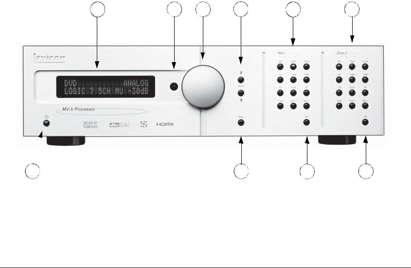
FRONT PANEL OVERVIEW
The MV-5 is shown below. The numbers in the front panel illustration correspond with the numbered items in the text.
1 |
2 |
3 |
4 |
5 |
6 |
|
10 |
|
9 |
8 |
7 |
1. |
Front Panel Display |
6. |
Zone 2 |
Input Selection Buttons |
|
2. |
IR Receiver |
7. |
Zone 2 |
Off Button |
|
3. |
Volume Knob |
8. |
Main Zone Off Button |
|
|
4. |
Mode Buttons |
9. |
Mute Button |
|
|
5. |
Main Zone Input Selection Buttons |
10. |
ON/Standby Button |
|
|
2-2

MV-5 |
Basic Operation |
1. FRONT PANEL DISPLAY
Use the front panel 2-line display to view the current input source, input type, listening mode, and volume level. The 2 x 20 character display also functions as a display for messages and menus, one line at a time.
2. IR RECEIVER
The IR receiver receives infrared commands from the MV-5 remote control. Blocking the IR receiver will prevent the remote control from functioning properly (unless using the optional RF-1 Receiver).
3. VOLUME KNOB
Use the volume knob to adjust the volume level. The adjustable volume range is -80 dB to +10 dB in 1 dB increments.
Note: The maximum volume level may be lower than +10 dB due to the output level settings of the speakers. Refer to Section 3: Setup for more information on setting the speaker output levels.
To adjust the Main Zone volume level:
Rotate the volume knob clockwise to increase or counter-clockwise to decrease the volume level in 1dB increments. The current volume level is indicated on the bottom right side of the 2-line front panel display.
To adjust the Zone 2 volume level:
1.Press and hold the front panel Zone 2 input selection button that corresponds with the current input source. For instance, if DVD is the current Zone 2 input source, press and hold the DVD input selection button in the Zone 2 area of the front panel.
2.While holding down the Zone 2 input button, rotate the volume knob clockwise to increase the volume or counter-clockwise to decrease the volume. On the front panel 2-line display, the bottom left side displays that Zone 2 is selected and the bottom right side indicates the current volume level.
Note: If you attempt to set the volume higher than the maximum or lower than the minimum volume levels, the displayed volume level flashes.
4. MODE BUTTONS
Use the Mode buttons to scroll to the previous ( ) or next ( ) available listening mode. Scrolling the Mode button reveals the entire list of listening modes available for the currently selected input and mode family. For more information on selecting listening modes, refer to Section 3: Setup.
5. MAIN ZONE INPUT SELECTION BUTTONS
Individually select each of the twelve inputs available in the Main Zone. When an input is selected, a blue LED lights in the corresponding input selection button. When the Main Zone is deactivated, pressing a Main Zone input selection button activates the corresponding input in the Main Zone.
When the MV-5 is in Standby, pressing a Main Zone input selection button powers on the MV-5, selects the input in the Main Zone, and turns off Zone 2.
6. ZONE 2 INPUT SELECTION BUTTONS
Individually select each of the twelve inputs available in Zone 2. When an input is selected, an amber LED lights on the corresponding input selection button. When Zone 2 is deactivated, pressing a Zone 2 input selection button activates the corresponding input in Zone 2.
2-3

Basic Operation |
Lexicon |
When the MV-5 is in Standby, pressing a Zone 2 input selection button powers on the MV-5, selects the input in Zone 2, and turns off the Main Zone.
7. ZONE 2 OFF BUTTON
Deactivates Zone 2. When Zone 2 is off, the Zone 2 OFF button on the front panel lights red.
8. MAIN ZONE OFF BUTTON
Deactivates the Main Zone. When the Main Zone is off, the Main Zone OFF button on the front panel lights red.
Note: Activating the Main Zone OFF button on the front panel turns off the audio, however the video continues to be output through both the analog and HDMI video outs. If using the HDMI Video In connection, only the HDMI video is output. If the analog Video In is used, then both analog and HDMI video is output. Main Zone OSD (On-Screen Display) menus are also still available.
9. MUTE BUTTON
Mutes the Main Zone and Zone 2 volumes. Press the MUTE button to mute the Main Zone volume level; “MUTE ON” appears in the 2-line and OSD displays. Press the MUTE button again to restore the volume to its original level. If a front panel Zone 2 input button is held down, then pressing the MUTE button on the front panel will mute the Zone 2 output.
On the remote control, pressing the volume button once while the volume is muted, turns off mute. Pressing and holding the Volume button, while the sound is muted, resets to the original pre-mute volume level and then increases or decreases the volume from that point, turning off mute.
The LED in the MUTE button lights red when the Main Zone mute is active, green when the Zone 2 mute is active, and amber when both Zones are muted. The volume can also be muted by using the MUTE button on the remote control, which functions in the same manner. However, the remote only mutes Zone 2 if the touch screen is in the “Zone 2” menu layer.
10. ON/STANDBY BUTTON
Toggles the MV-5 between On and Standby. The rear panel Power Switch must be set to the ON position for the Standby button to be active. When the MV-5 is in the standby mode, pressing the Standby button turns the unit on and changes the light in the Standby button from red to blue. Power is still supplied to the
MV-5 when standby mode is activated.
When the rear panel Power Switch is set to the ON position or AC power is applied or restored, the MV-5 automatically enters the standby mode.
Note: When taken out of standby, the MV-5 activates the Zone inputs that were active in the previous operating session.
2-4

Basic Operation |
Lexicon |
REAR PANEL OVERVIEW
The MV-5 rear panel is shown below. The numbers in the rear panel illustrations correspond with the numbered items in the text.
1 |
2 |
3 |
4 |
5 |
6 |
7 |
8 |
9 |
10 |
11 |
|
19 |
18 |
17 |
16 |
15 |
14 |
13 |
12 |
|
1. |
8-CH Analog Audio Input Connector |
7. |
Component Video Input Connectors |
14. |
RS-232 Connector |
||||
|
Array |
|
|
8. |
Component Video Output Connector |
15. |
Preamplifier Outputs |
||
|
|
|
|
||||||
2. |
Digital Audio Input Connectors |
|
9. |
HDMI Input Connectors |
|
16. |
Dock Connector |
||
|
|
|
|
|
|||||
3. |
USB Connector |
|
|
10. |
HDMI Output Connector |
|
17. |
Zone 2 Audio Output Connectors |
|
|
|
|
|
|
|||||
4. |
IR Input Connector |
|
|
11. |
Power Switch |
|
18. |
Stereo Analog Audio Input Connectors |
|
|
|
|
|
|
|||||
5. |
S-Video/Composite Input Connectors |
|
12. |
AC Input Connector |
|
19. |
Microphone Input Connector |
||
|
|
|
|
|
|||||
6. |
S-Video/Composite Ouput Connectors |
|
13. |
Trigger Output Connectors |
|
|
|
||
|
|
|
|
|
|
|
|||
2-5

Basic Operation |
Lexicon |
CAUTION!
Never make or break connections to the MV-5 unless the MV-5 and all associated components are powered off.
1. 8-CH ANALOG AUDIO INPUT CONNECTOR ARRAY
Provides 8-channel analog audio input via eight RCA connectors labeled Front L/R, Center, LFE, Side L/R and Rear L/R. These inputs are used to connect source devices such as high-resolution DVD players, DVD-Audio, or SACD players with discrete analog audio outputs. Depending on the source device in use, all eight connectors may be used, although only the Front L/R, Center, Side L/R, and LFE are required for 5.1 analog audio signals.
2. DIGITAL AUDIO INPUT CONNECTORS
Provide digital audio input via four S/PDIF optical (TOSLINK) and four S/PDIF coaxial (RCA) input connectors. Connectors are compatible with most PCM, Dolby Digital, and DTS sources.
3. USB CONNECTOR
Provides a USB port to connect to a PC computer, enabling the user to listen to audio from the computer through the MV-5 Processor. The USB connector port is a “mini B” connector and requires a USB cable (not included). See Section 5: PC & Dock Controls for more information on the playback of computer audio.
connection) or mono plug (Tip/Sleeve connection).
5. S-VIDEO/COMPOSITE INPUT CONNECTORS
Provide the S-Video & Composite analog video inputs. Four composite video connectors labeled 1 to 4 and four S-Video connectors labeled 1 to 4 are available.
6. S-VIDEO/COMPOSITE OUTPUT CONNECTORS
Provide the S-Video & Composite video outputs. One composite video connector and one S-Video connector are available.
7. COMPONENT VIDEO INPUT CONNECTORS
Provide inputs that can be used with any source device that is equipped with analog Y/Pr/Pb or RGB component video outputs. Three inputs, labeled Component Video 1 to 3, are supplied.
8. COMPONENT VIDEO OUTPUT CONNECTOR
Provides one component output that can be used with any device that is equipped with analog Y/Pr/Pb or RGB component video intputs.
9. HDMI INPUT CONNECTORS
Provide two HDMI inputs for devices such as a DVD player or HDTV tuner.
4. IR INPUT CONNECTOR
Accepts input of IR signals from infrared distribution equipment via one 3.5mm jack that accepts a stereo plug (Tip/Ring/Sleeve
10. HDMI OUTPUT CONNECTOR
Provides one HDMI output for HDMI-equipped video monitors.
2-6

MV-5 |
Basic Operation |
11. POWER SWITCH
Use the Power Switch to connect or disconnect power from the AC Input connector to the MV-5 Processor. When the MV-5 is powered on, the front panel Standby button or remote control ON & OFF buttons can be used to activate and deactivate standby mode. When the MV-5 is powered off via the rear panel switch, the standby and ON modes are not available.
12. AC INPUT CONNECTOR
Provides power to the MV-5 through the supplied power cord.
13. TRIGGER OUTPUT CONNECTORS
Provide a 12V DC output to control connected components. Two trigger output connectors are available as 3.5 mm mono mini phone jacks. The OUT 1 connector is the power trigger and is not configurable; it is activated when the MV-5 is powered on or taken out of Standby mode, and deactivated when the MV-5 is powered off, either from the rear panel or by putting the MV-5 into Standby mode. The OUT 2 connector can be configured independently for each input, refer to Section 3: Setup for more information on how to configure the OUT 2 trigger.
Note: The OUT 2 trigger is referred to as “TRIGGER 2” in the Input Setup menu.
14. RS-232 CONNECTOR
The RS-232 serial connector provides serial remote control through a standard RS-232 connection. Refer to the Lexicon website (www.lexicon.com) for more details on controlling the MV-5 Processor via the RS-232 connection.
15. PREAMPLIFIER OUTPUTS
Provide output for external power amplifiers for applications that require them.
16. DOCK CONNECTOR
Provides an interface for an iPod, which can then be accessed through the MV-5 rear panel. To use this feature, the D-1 Dock option must be installed to the DOCK connector. With a compatible iPod connected to the MV-5, selecting the DOCK input allows you to play audio files from the iPod. You can view and navigate through the iPod menus using the MV-5 remote control. For more information on the Dock option and how to use your MV-5 with an iPod, refer to Section 5: PC & Dock Controls.
17. ZONE 2 AUDIO OUTPUT CONNECTORS
Provide preamplifier audio outputs for Zone 2.
18. STEREO ANALOG AUDIO INPUT CONNECTORS
Provide stereo analog audio input. Six stereo analog audio input RCA connectors labeled 1 to 6 are available.
19. MICROPHONE INPUT CONNECTOR
Provides a microphone input for system calibration. The microphone input is only for use with the supplied microphone during the system calibration process. See Section 3: Setup for more information regarding system calibration and setup.
2-7

Basic Operation |
Lexicon |
PC & DOCK OVERVIEW
The PC & Dock inputs are the only “hard-wired” inputs in the MV-5 Processor. Unlike the other inputs, both have very specific audio-only functionality.
The PC input is tied to the USB input on the rear panel and is for use with media player software on a connected PC computer. The Dock input is for use with the optional D-1 Dock accessory and is tied to the DOCK input on the rear panel. This input is only for use with iPod players.
While both of these inputs have devoted Remote Control menu controls, there are NO front panel controls for use with the PC and DOCK inputs.
For more information about the PC & Dock operation, refer to
Section 5: PC & Dock Controls.
REMOTE CONTROL OVERVIEW
The MV-5 Processor remote control provides full operation of the MV-5 including commands, such as menu navigation, that are not available from the front panel. It is also designed to provide control for the entire home theater system. This section provides a brief overview of the remote control functions used to control the MV-5 Processor. For detailed universal remote control operation, programming instructions, and manufacturing codes, refer to
Appendix C.
OPERATION CONSIDERATIONS
The following factors can improve or impede remote control operation.
Note the following before operating the MV-5 remote control:
•The remote control must be in line-of-sight with the front panel IR receiver (unless using the optional RF-1 Receiver). Eliminate obstructions between the remote control and the IR receiver. The remote control may become unreliable if strong sunlight or fluorescent light shines on the MV-5 IR receiver.
•For optimal performance, position the remote control within a 30-degree angle no more than 40 to 60 feet (12.2m to 18.3m) from the MV-5. Placing the MV-5 inside a smoked glass cabinet will reduce the remote control range.
•Remote controls for different components can interfere with one another. Avoid using remote controls for different components at the same time.
•Remote control batteries should be replaced as needed.
•To control the MV-5, the touch screen of the remote control must be in the “LEX” or “ZONE 2” menu layers. The Volume +/ - and Mute controls, however, are always active, regardless of the active menu layer. The remote control ships from the factory set to the “MAIN” menu layer.
2-8

MV-5 |
Basic Operation |
MV-5 MENU OVERVIEW
When the remote control touch screen is in the “LEX” or “ZONE 2” menu layers, pressing MENU or SELECT on the MV-5 remote control accesses the menu controls for the MV-5 Processor. The MAIN MENU is the root
directory of the MV-5 menu structure and has three branches: AUDIO CONTROLS, VIDEO STATUS, and SETUP.
Note: The DVD menu layer of the touch screen controls the Lexicon RT-20 and RT-10, if installed.
The AUDIO CONTROLS menu controls the audio-specific parameters, such as treble and bass, as well as providing an audio status menu. Refer to Section 4: Audio Controls & Video Status for more information.
The VIDEO STATUS menu is an information-only menu identifying the current video status of the MV-5 Processor. For more information, refer to Section 4: Audio Controls & Video Status.
The SETUP menu controls all aspects of setting up the MV-5 Processor. Refer to Section 3: Setup for more information.
The MV-5 menu structure can be viewed on the OSD (On-Screen Display), which is a 480i or 480p video output signal to your monitor, or on the front panel 2-line display, which displays the menus one line at a time using the remote control navigation controls. The front panel 2-line display can also be viewed on the OSD, in 480i resolution only.
Note: When the MV-5 menu structure is entered, most front panel buttons and the remote control buttons are disabled until the menu structure is exited. The exceptions are the Volume Knob and Standby Button on the front panel and the remote control Volume, Mute, and OFF buttons. Note also that the disabled condition of the remote control only affects the “LEX” and “ZONE 2” menu layers.
MENU NAVIGATION
Use the remote control arrow buttons to navigate the MV-5 menu structure, shown in detail in Appendix B. The Command Matrix Table located later in this chapter indicates the navigation commands that the remote control buttons perform when the MV- 5 command bank is activated by selecting the “LEX” or “ZONE 2” options on the remote control touch screen.
Arrow |
Navigation Functions |
|
|
(for “LEX” and “ZONE2” menu layers) |
|
||
|
|
||
|
|
|
|
|
When a menu is open, press the remote control |
arrow to |
|
|
select the highlighted menu parameter. The menu parameter |
||
|
will blink to indicate that it is selected. |
|
|
|
|
|
|
|
When a menu is open, press the |
arrow to close the current |
|
|
menu and, in most cases, open the previous menu. Subsequent |
||
|
presses continue to close the current menu and open the |
||
|
previous menu until the MAIN MENU is closed. |
|
|
|
|
|
|
|
When a menu is open, press the |
and arrow buttons to scroll |
|
|
upward and downward through the complete list of menu param- |
||
|
eters. The highlighted menu item appears in the front panel |
||
|
display. All menu items appear in the OSD. The cursor |
||
|
automatically wraps to the next menu parameter when the first or |
||
|
last menu item is passed. |
|
|
|
When a menu parameter is selected and blinking, press the and |
||
|
arrow buttons to scroll through the available parameter |
||
|
options. |
|
|
|
|
||
SELECT |
Press the SELECT button to open the menu structure, open a |
||
|
menu branch, or select a menu parameter. |
|
|
|
|
|
|
MENU |
Press the MENU button to open the menu structure. |
|
|
|
|
||
EXIT |
When the menu is open, press the EXIT button to leave the menu. |
||
|
Unlike the arrow button which closes a menu layer, the EXIT |
||
|
button completely closes the menu structure. |
|
|
|
|
|
|
2-9
Basic Operation |
Lexicon |
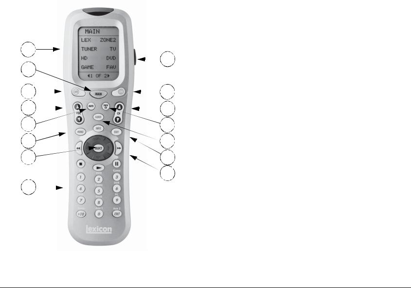
REMOTE CONTROL BUTTONS
1
2 |
|
|
|
|
|
|
9 |
|
|
|
|
|
|
|
|||
|
|
|
|
|
|
|
|
|
3 |
|
|
|
|
|
|
10 |
|
|
|
|
|
|
|
|||
4 |
|
|
|
|
|
|
11 |
|
|
|
|
|
|
|
|||
5 |
|
|
|
|
|
12 |
||
6 |
|
|
|
|
|
13 |
||
7 |
|
|
|
|
|
14 |
||
|
|
|
|
|
|
15 |
||
8 |
|
|
|
|
|
|
|
|
|
|
|
|
|
|
|
|
|
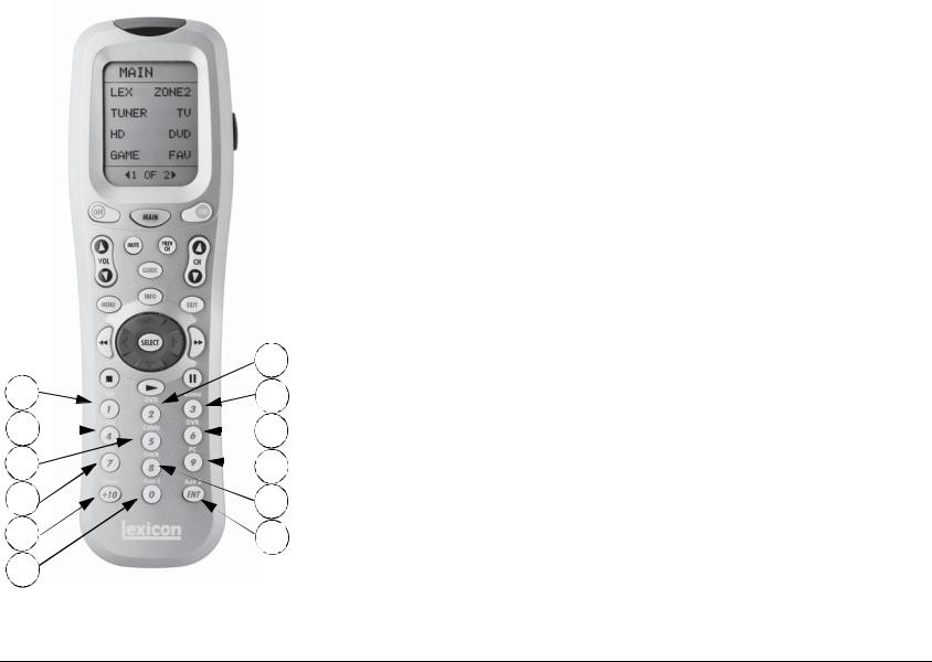
1.Touch Screen (component and function buttons)
2.MAIN remote control touch screen menu
3.OFF
4.VOLUME (+/-)
5.MUTE
6.MENU
7.SELECT & Navigation (left, right, up, & down)
8.Number Keypad & ENT (Enter)
9.LIGHT (back light for the remote control)
10.ON
11.CHANNEL (+/-)
12.PREV CH (Previous Channel)
13.GUIDE & INFO
14.EXIT
15. Transport functions (PLAY , STOP , RW , PAUSE ||, & FF ) for source components
Note: These are the names and functions for the universal remote control.
For the MV-5 specific remote control functions, refer to the Command
Matrix on the following page.
Note: The number call-outs on the figure above correlate with the numbers listed to the right.
2-10
MV-5 |
Basic Operation |
MENU OPTIONS
Selecting a menu option can open another menu within the menu structure. For example, selecting SETUP from the MAIN MENU opens the SETUP menu.
MAIN MENU
AUDIO CONTROLS VIDEO STATUS
SETUP
SETUP
DISPLAY SETUP SPEAKER/EQ SETUP INPUT SETUP SURROUND CONFIG DOLBY CONFIG MUTE LEVELS POWER ON SETTINGS
MENU ITEM SELECTION
Use the remote control arrows to navigate the menu structure.
To select a menu item in an open menu:
1.Press the Menu or Select buttons to enter the Menu structure.
2.Navigate to the desired menu.
3. |
Press the remote control |
and |
arrows to highlight the |
||
|
desired menu item. |
|
|
|
|
4. |
When the desired menu item is highlighted, press the |
arrow |
|||
|
or SELECT button to select the highlighted item. If an option is |
||||
|
selected, another menu opens. When an adjustable parameter is |
||||
|
selected, the current selection will blink to indicate that it is |
||||
|
selected. Use the |
and |
arrows to scroll through the available |
||
|
options for the selected parameter. When the desired parameter |
||||
|
option is highlighted, press the |
arrow on the remote control to |
|||
|
select the option. |
|
|
|
|
REMOTE CONTROL LIGHT BUTTON
The remote control is fully back lit, making it very useful in low-light conditions. Press the LIGHT button on the right side of the remote to back light all of the buttons and the LCD touch screen. To turn off the back light, press the LIGHT button again or wait. Ten seconds after the last button is pressed, the back light will automatically shut off.
COMMAND MATRIX
The command matrix table, starting on the next page, lists the commands that each remote control button performs in each menu setting.
Note: A brief description of each function is given in the table but refer to the Table of Contents for additional information on each function. For additional information on using and programming the remote control, refer to Appendix C.
2-11

Basic Operation |
Lexicon |
1 |
|
|
|
|
|
2 |
3 |
||||
|
|||||
4 |
5 |
||||
|
|||||
6 |
|
|
|
7 |
|
8 |
|
|
|||
|
|
|
|
||
9 |
|||||
|
|||||
10 |
|
|
|
|
|
Note: The number call-outs on the figure above correlate with the numbers in the adjoining table.
|
MAIN |
LEX PAGE1 |
LEX PAGE2 |
LEX PAGE3 |
LEX PAGE4 |
|
|
|
|
|
|
|
|
1 |
Menu Name - |
Menu Name - LEX |
Menu Name - LEX |
Menu Name - LEX |
Menu Name - LEX |
|
|
||||||
|
MAIN* |
|
|
|
(iPod controls) |
(PC controls) |
|
|
|
|
|
|
|
2 |
LEX |
|
L7 |
EQ |
IPOD- |
PC- |
|
|
|||||
|
Enters the Lexicon |
Selects the Logic 7 |
Toggles the Auto EQ |
iPod |
PC |
|
|
MV-5 menu layer |
listening mode family |
parameter between |
|
|
|
|
|
|
|
ON & OFF. |
|
|
|
|
|
|
|
|
|
3 |
ZONE2 |
|
STER |
PRE1 |
IPOD+ |
PC+ |
|
|
|||||
|
Enters the Lexicon |
Selects the Stereo |
Sets the MV-5 to the |
iPod |
PC |
|
|
MV-5 Zone 2 menu |
listening mode family |
Autocal Preset 1 |
|
|
|
|
layer |
|
|
saved values |
|
|
|
|
|
|
|
|
|
4 |
TUNER |
|
DOLBY |
PRE2 |
CLIK |
PC II |
|
|
|||||
|
(Does not affect the |
Selects the Dolby |
Sets the MV-5 to the |
iPod wheel click, |
PC Play/Pause |
|
|
MV-5) |
|
listening mode family |
Autocal Preset 2 |
counterclockwise |
|
|
|
|
|
saved values |
|
|
|
|
|
|
|
|
|
5 |
TV |
|
DTS |
PRE3 |
CLIK |
(unused) |
|
|
|||||
|
(Does not |
affect the |
Selects the DTS |
Sets the MV-5 to the |
iPod wheel click, |
|
|
MV-5) |
|
listening mode family |
Autocal Preset 3 |
clockwise |
|
|
|
|
|
saved values |
|
|
|
|
|
|
|
|
|
6 |
HD |
|
DSP |
TREB- |
MENU |
(unused) |
|
|
|||||
|
(Does not |
affect the |
Selects the DSP |
Lowers the Treble |
iPod MENU button |
|
|
MV-5) |
|
listening mode family |
parameter |
|
|
|
|
|
|
|
|
|
7 |
DVD |
|
AUDIN |
TREB+ |
SEL |
(unused) |
|
|
|||||
|
Enters the Lexicon |
Selects either Digital |
Raises the Treble |
iPod SELECT button |
|
|
|
RT-10/RT-20 menu |
or Analog Audio. |
parameter |
|
|
|
|
|
|
|
|
|
|
8 |
GAME |
|
TONE |
BASS- |
II |
(unused) |
|
|
|||||
|
(Does not |
affect the |
Toggles the Tone |
Lowers the Bass |
iPod Play/Pause |
|
|
MV-5) |
|
Control parameter |
parameter |
button |
|
|
|
|
between ON & OFF. |
|
|
|
|
|
|
|
|
|
|
9 |
FAV |
|
ZOOM |
BASS+ |
|
(unused) |
|
|
|
||||
|
(Does not affect the |
(unused) |
Raises the Bass |
|
|
|
|
MV-5) |
|
|
parameter |
|
|
|
|
|
|
|
|
|
10 |
MENU PAGE - <ACTIVE PAGE> OF <TOTAL PAGES> |
|
|
|||
|
|
|
||||
|
Touch or to scrolll between the menu pages |
|
|
|||
|
|
|
|
|
|
|
*The Menu Name is not a functional command. It is simply a label identifying which menu or sub-menu the touch screen currently displays.
2-12
MV-5 |
Basic Operation |
11 |
|
|
|
|
|
|
12 |
13 |
|||||
14 |
15 |
|||||
16 |
|
|
|
|
17 |
|
|
|
|||||
18 |
|
|
19 |
|||
|
||||||
Note: The number call-outs on the figure above correlate with the numbers in the adjoining table.
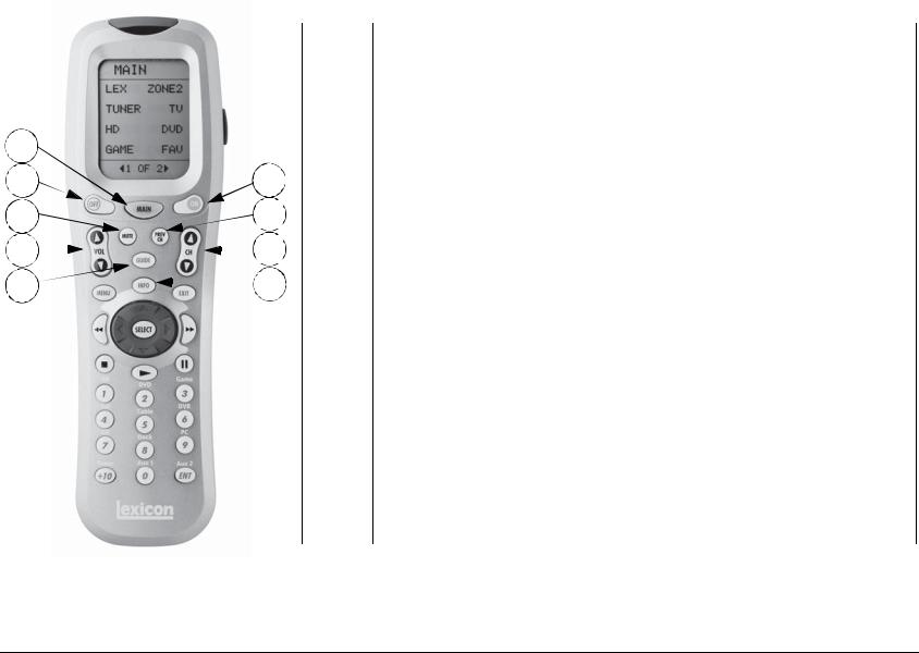
MAIN* |
LEX |
ZONE 2 |
|
PAGE1-4 |
PAGE 1-3 |
||
|
|||
|
|
|
11 |
MAIN* |
|
|
|
|
|
|
|
|
||
|
Returns to the Main layer of the remote control |
|
|||
|
|
|
|
|
|
12 |
OFF |
|
Puts the MV-5 Processor into Standby |
|
|
|
|
|
|||
|
|
|
|
|
|
13 |
ON |
|
Turns on the MV-5 Processor from Standby |
|
|
|
|
|
|||
|
|
|
|
|
|
14 |
MUTE |
|
Mutes the Main Zone Volume |
Mutes the Zone 2 |
|
|
|
||||
|
|
|
|
|
Volume |
|
|
|
|
|
|
15 |
PREV CH |
(unused) |
|
||
|
|
||||
|
|
|
|
|
|
16 |
VOL |
or VOL |
Main Zone |
Zone 2 |
|
|
|||||
|
|
|
VOL |
or VOL |
VOL or VOL |
|
|
|
|
|
|
17 |
CH |
or CH |
Main Zone |
(unused) |
|
|
|||||
|
|
|
MODE |
or MODE |
|
|
|
|
|
|
|
18 |
GUIDE |
|
Steps through the VIDEO STATUS menu |
|
|
|
|
|
|||
|
|
|
|
|
|
19 |
INFO |
|
Steps through the AUDIO STATUS menu |
|
|
|
|
|
|||
|
|
|
|
|
|
*The MAIN menu level does NOT control the MV-5. The remote control touch screen heading must read “LEX” or “ZONE 2” in order to control the MV-5 Processor.
2-13
Basic Operation |
Lexicon |
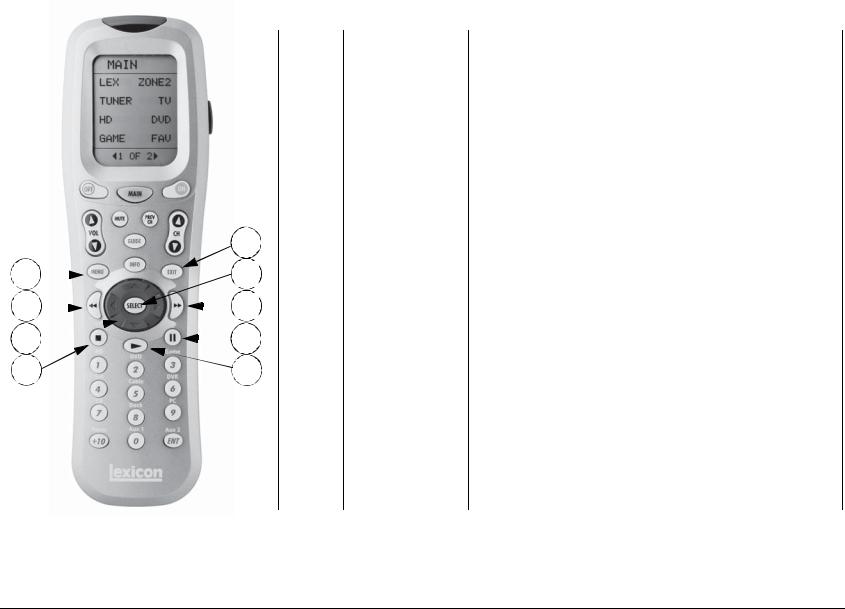
MAIN* |
LEX |
ZONE 2 |
|
PAGE1-4 |
PAGE 1-3 |
||
|
|||
|
|
|
|
|
|
|
|
|
|
|
20 |
MENU |
Enters OSD menu |
|
|
|
|
|
|
|
|
|
|
|
||
|
|
|
|
|
|
|
|
|
|
|
|
|
|
|
|
|
|
|
|
21 |
EXIT |
Exits OSD menu |
|
|
|
|
|
|
|
|
|
|
|
||
|
|
|
|
|
|
|
|
|
|
|
|
|
|
|
|
|
|
|
|
22 |
|
(unused) |
|
|
|
|
|
|
|
|
|
|
|
|
|
|
|
|
|
|
|
|
|
|
REWIND |
|
|
|
|
|
|
|
|
|
|
|
|
|
|
|
|
|
|
|
21 |
23 |
SELECT |
Enters OSD menu, |
|
||
|
|
|
|
|
|
|
|||||
|
|
|
|
|
|
|
While in OSD menu, selects menu items |
|
|||
20 |
|
|
|
|
23 |
|
|
|
|
||
|
|
|
|
24 |
|
Used for OSD menu navigation |
|
||||
|
|
|
|
|
|
|
|||||
22 |
|
|
|
|
|
25 |
|
Arrows |
If not in the OSD menu structure, no function. |
|
|
|
|
|
|
|
|
|
|
|
|||
|
|
|
|
|
|||||||
|
|
|
|
|
|
|
|
||||
24 |
|
|
|
|
|
|
27 |
25 |
|
(unused) |
|
|
|
|
|
|
|
|
|
|
|||
|
|
|
|
|
|
FAST FORWARD |
|
|
|||
|
|
|
|
|
|||||||
26 |
|
|
|
|
28 |
|
|
|
|
||
|
|
|
|
26 |
|
Main Zone OFF |
Zone 2 OFF |
||||
|
|
|
|
|
|
||||||
|
|
|
|
|
|
|
|
|
STOP |
|
|
|
|
|
|
|
|
|
|
|
|
|
|
|
|
|
|
|
|
|
|
27 |
|| |
Changes Front panel display illumination |
(unused) |
|
|
|
|
|
|
|
|
|
|||
|
|
|
|
|
|
|
|
|
PAUSE |
|
|
|
|
|
|
|
|
|
|
|
|
|
|
|
|
|
|
|
|
|
|
28 |
|
(unused) |
|
|
|
|
|
|
|
|
|
|
|
|
|
|
|
|
|
|
|
|
|
|
PLAY |
|
|
|
|
|
|
|
|
|
|
|
|||
Note: The number call-outs on the figure above |
*The MAIN menu level does NOT control the MV-5. The remote control touch screen heading must read “LEX” or “ZONE 2” |
||||||||||
in order to control the MV-5 Processor. |
|
|
|||||||||
correlate with the numbers in the adjoining table. |
|
|
|
|
|||||||
2-14
MV-5 |
Basic Operation |
|
30 |
|||
29 |
31 |
|||
32 |
|
|
|
34 |
|
|
|||
33 |
37 |
|||
35 |
36 |
|||
38 |
40 |
|||
39 |
|
|
|
|
Note: The number call-outs on the figure above correlate with the numbers in the adjoining table.
|
|
MAIN* |
LEX |
ZONE 2 |
|
|
PAGE1-4 |
PAGE 1-3 |
|
|
|
|
||
|
|
|
|
|
29 |
1 |
|
Main Zone |
Zone 2 |
|
|
HD input |
HD input |
|
|
|
|
||
|
|
|
|
|
30 |
2 |
|
Main Zone |
Zone 2 |
|
|
DVD input |
DVD input |
|
|
|
|
||
|
|
|
|
|
31 |
3 |
|
Main Zone |
Zone 2 |
|
|
Game input |
Game input |
|
|
|
|
||
|
|
|
|
|
32 |
4 |
|
Main Zone |
Zone 2 |
|
|
Sat input |
Sat input |
|
|
|
|
||
|
|
|
|
|
33 |
5 |
|
Main Zone |
Zone 2 |
|
|
Cable input |
Cable input |
|
|
|
|
||
|
|
|
|
|
34 |
6 |
|
Main Zone |
Zone 2 |
|
|
DVR input |
DVR input |
|
|
|
|
||
|
|
|
|
|
35 |
7 |
|
Main Zone |
Zone 2 |
|
|
CD input |
CD input |
|
|
|
|
||
|
|
|
|
|
36 |
8 |
|
Main Zone |
Zone 2 |
|
|
Dock input |
Dock input |
|
|
|
|
||
|
|
|
|
|
37 |
9 |
|
Main Zone |
Zone 2 |
|
|
PC input |
PC input |
|
|
|
|
||
|
|
|
|
|
38 |
+10 |
|
Main Zone |
Zone 2 |
|
|
Tuner input |
Tuner input |
|
|
|
|
||
|
|
|
|
|
39 |
0 |
|
Main Zone |
Zone 2 |
|
|
Aux 1 input |
Aux 1 input |
|
|
|
|
||
|
|
|
|
|
40 |
ENT |
|
Main Zone |
Zone 2 |
Enter |
|
Aux 2 input |
Aux 2 input |
|
|
|
|||
|
|
|
|
|
*The MAIN menu level does NOT control the MV-5. The remote control touch screen heading must read “LEX” or “ZONE 2” in order to control the MV-5 Processor.
2-15

Basic Operation |
Lexicon |
2-16

|
3 |
|
Setup |
Setup ......................................................................................... |
3-2 |
Display Setup ............................................................................. |
3-3 |
Speaker/EQ Setup ...................................................................... |
3-5 |
Manual ..................................................................................................... |
3-6 |
Semi Autocal............................................................................................. |
3-6 |
Full Autocal ............................................................................................... |
3-6 |
Manual Speaker Setup................................................................ |
3-8 |
Speakers Menu.......................................................................................... |
3-9 |
Speaker Distances Menu ......................................................................... |
3-10 |
Output Levels Menu................................................................................ |
3-11 |
Input Setup .............................................................................. |
3-13 |
Advanced Video ...................................................................................... |
3-19 |
Listening Modes....................................................................... |
3-22 |
Selecting a Listening Mode ..................................................................... |
3-22 |
DTS + Dolby Listening Modes ................................................................. |
3-22 |
Available Listening Modes ....................................................................... |
3-23 |
Listening Mode Descriptions ................................................................... |
3-26 |
5.1-channel & 7.1-channel Direct Inputs................................................. |
3-28 |
DTS & Dolby Status Displays................................................................... |
3-28 |
Surround Configuration ........................................................... |
3-29 |
Dolby Configuration................................................................. |
3-31 |
Mute Levels.............................................................................. |
3-32 |
Power On Settings ................................................................... |
3-32 |
Setup |
Lexicon |
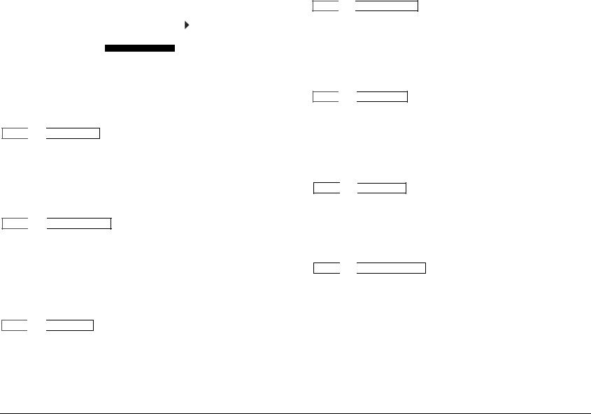
SETUP
Selecting SETUP from |
|
|
|
|
|
|
|
|
|
MAIN MENU |
|
|
|
SETUP |
|
||
the MAIN |
MENU |
|
|
|
||||
|
AUDIO CONTROLS |
|
|
DISPLAY SETUP |
||||
opens the |
SETUP |
|
|
|
||||
|
VIDEO STATUS |
|
|
SPEAKER/EQ SETUP |
||||
menu. |
|
|
SETUP |
|
|
|
INPUT SETUP |
|
|
|
|
|
|||||
|
|
|
|
|
|
|
SURROUND CONFIG |
|
|
|
|
|
|
|
|
DOLBY CONFIG |
|
|
|
|
|
|
|
|
MUTE LEVELS |
|
|
|
|
|
|
|
|
POWER ON SETTINGS |
|
|
|
|
|
|
|
|
|
|
DISPLAY SETUP
SETUP 

 DISPLAY SETUP
Opens the DISPLAY SETUP menu, which is used to customize the OSD and front panel display, as well as other display-related parameters. See the “Display Setup” section on the following page for more information.
SPEAKER/EQ SETUP
SETUP 

 SPEAKER/EQ SETUP
Opens the SPEAKER/EQ SETUP menu, which is used to configure the Main Zone and Zone 2 audio output connectors for the desired speaker setup, set speaker cross-overs, and calibrate distances and output levels. See the “Speaker/EQ Setup” section found later in this chapter for more information.
INPUT SETUP
SETUP 

 INPUT SETUP
Opens the INPUT SETUP menu, which is used to change input names, assign audio and video input connectors, select preferred listening modes and configure Main Zone and Zone 2 settings. See the “Input Setup” section found later in this chapter for more information.
SURROUND CONFIGURATION
SETUP 

 SURROUND CONFIG
Opens the SURROUND CONFIG menu, which is used to customize the listening modes that are available for the currently selected input. See the “Surround Configuration” section found later in this chapter for more information.
DOLBY CONFIGURATION
SETUP 

 DOLBY CONFIG
Opens the DOLBY CONFIG menu, which is used to customize the Dolby listening modes to your personal preferences. See the“Dolby Configuration” section found later in this chapter for more information.
MUTE LEVELS
SETUP 

 MUTE LEVELS
Opens the MUTE LEVELS menu, which is used to set the mute level controls. See the “Mute Levels” section found later in this chapter for more information.
POWER ON SETTINGS
SETUP 

 POWER ON SETTINGS
Opens the POWER ON SETTINGS menu, which is used to configure the power on volume level and the Dock auto power feature. See the “Power On Settings” section found later in this chapter for more information.
Note: When a source is active, changing some audio or video parameters may cause the Main Zone audio to briefly mute the incoming source. If Zone 2 is set to DOWN MIX, the Zone 2 audio will also briefly mute.
3-2
MV-5 |
Setup |
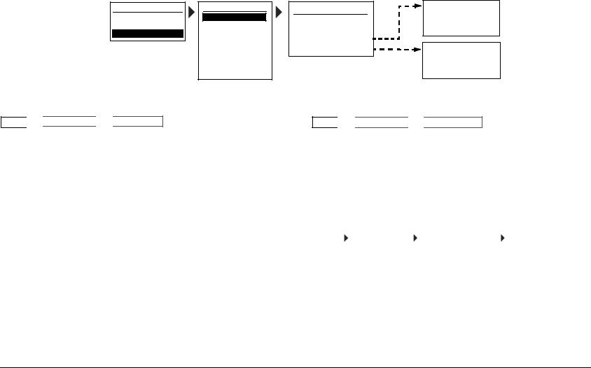
DISPLAY SETUP
Selecting the SETUP menu DISPLAY SETUP option opens the DISPLAY SETUP menu, which is used to customize the OSD and front panel display and setup other display-related features.
MAIN MENU
AUDIO CONTROLS VIDEO CONTROLS
SETUP
SETUP
DISPLAY SETUP
SPEAKER/EQ SETUP INPUT SETUP SURROUND CONFIG DOLBY CONFIG MUTE LEVELS POWER ON SETTINGS
DISPLAY SETUP
CONNECTION: HDMI/DVI HDMI AUDIO OUT: NO ON-SCREEN DISPLAY FRONT PANEL DISPLAY
ON-SCREEN DISPLAY
2-LINE OSD: 3s
MENU TIME OUT: 30s
FRONT PANEL DISPLAY BRIGHTNESS: FULL TIME OUT: NONE
CONNECTION |
ANALOG, HDMI/DVI |
SETUP 

 DISPLAY SETUP

 CONNECTION
Selects the CONNECTION parameter, which identifies the active video output connectors on the MV-5 rear panel. The following list of conditions identify the behavior of this parameter.
•If ANALOG is selected, only the analog video connectors are available and will output the video signal.
•If HDMI/DVI is selected, both the analog and HDMI video connectors are available and will output the video signal.
•If the video input is set to HDMI and the CONNECTION parameter is set to ANALOG, then no video is output.
•If the HDMI video input is copy-protected (HDCP), no video is output on the analog output connectors. This is a requirement of HDCP and not a limitation of the MV-5 Processor.
HDMI AUDIO OUT |
YES, NO |
SETUP 

 DISPLAY SETUP

 HDMI AUDIO OUT
Selects the HDMI AUDIO OUT parameter, which identifies if audio is sent on the HDMI output. If the HDMI AUDIO OUT parameter is set to YES, then a two-channel DOWN MIX of the source audio is sent over the HDMI connection at the maximum bit rate of the display’s audio system. This audio stream is in addition to the normal audio outputs. If the parameter is set to NO, this audio is not sent.
2-LINE OSD |
|
OFF, 3, 4, 5, 6 SECONDS |
|||||
|
|
|
|
|
|
|
|
SETUP |
|
DISPLAY SETUP |
|
ON-SCREEN DISPLAY |
|
2-LINE OSD |
|
Selects the 2-LINE OSD parameter from the On-Screen Display (OSD) menu. The 2-Line OSD parameter identifies the length of time that the 2-line OSD is displayed and can be set to display from three to six seconds in one-second increments. If OFF is selected, then the 2-line OSD is not displayed.
Note: If OFF is selected, the menu screens are still displayed. This parameter only affects the 2-line OSD display, which is identical to the front panel 2-line display.
3-3

Setup |
Lexicon |
MENU TIME OUT |
|
NONE, 30, 40, 50, 60 SECONDS |
|||||
|
|
|
|
|
|
|
|
SETUP |
|
DISPLAY SETUP |
|
ON-SCREEN DISPLAY |
|
MENU TIME OUT |
|
Selects the MENU TIME OUT parameter from the On-Screen Display (OSD) menu. This parameter identifies the length of time before the OSD menu times out and can be set from 30 to 60 seconds in ten-second increments. If NONE is selected, then the OSD will not turn off automatically.
CAUTION!
The NONE selection should only be used with caution. If the system includes a plasma display, or other display types sensitive to image burn-in, and the OSD Menu Time Out parameter is set to NONE, the OSD menu image can be burned into the monitor display.
BRIGHTNESS |
|
|
|
FULL, HALF, OFF |
|||
|
|
|
|
|
|
|
|
SETUP |
|
DISPLAY SETUP |
|
FRONT PANEL DISPLAY |
|
BRIGHTNESS |
|
Selects the BRIGHTNESS parameter from the Front Panel Display menu, which selects the brightness of the 2-line front panel display. The parameter can be set to FULL, HALF, or OFF. If set to OFF, then the front panel display is off.
On the remote control, this parameter is controlled by the || (Pause) button while in the touch screen “LEX” menu layer.
Note: When the MV-5 is powered off or put into Standby mode, any changes to the BRIGHTNESS parameter are not saved. So when the MV-5 is powered on or taken out of Standby mode again, the BRIGHTNESS parameter will be set to FULL.
TIME OUT |
|
NONE, 1 TO 10 SECONDS |
|||||
|
|
|
|
|
|
|
|
SETUP |
|
DISPLAY SETUP |
|
FRONT PANEL DISPLAY |
|
TIME OUT |
|
Selects the TIME OUT parameter from the Front Panel Display menu. This parameter identifies the length of time before the front panel 2-line display times out. The parameter can be set from 1 to 10 seconds in one-second increments. If NONE is selected, then the 2-line front panel display is always on when the MV-5 is on.
3-4
 Loading...