


MPX R1
MIDI Remote Controller
Version 2
User Guide
Unpacking and Inspection
After unpacking the MPX R1, save all packing materials in case you ever need to ship the unit. Thoroughly inspect the unit and packing materials for signs of damage. Report any shipment damage to the carrier at once; report equipment malfunction to your dealer.
Notice
This equipment generates and uses radio frequency energy and if not installed and used properly, that is, in strict accordance with the manufacturer's instructions, may cause interference to radio and television reception. It has been type tested and found to comply with the limits for a Class B computing device in accordance with the specifications in Subpart J of Part 15 of FCC Rules, which are designated to provide reasonable protection against such interference in a residential installation. However, there is no guarantee that interference will not occur in a particular installation. If this equipment does cause interference to radio or television reception, which can be determined by turning the equipment OFF and ON, the user is encouraged to try to correct the interference by one or more of the following measures:
Reorient the receiving antenna
Relocate the computer with respect to the receiver Move the computer away from the receiver
Plug the computer into a different outlet so that the computer and receiver are on different branch circuits.
If necessary, the user should consult the dealer or an experienced radio/television technician for additional suggestions. The user may find the following booklet prepared by the Federal Communications Commission helpful:
"How to identify and Resolve Radio/TV Interference Problems."
This booklet is available from the U.S. Government Printing Office, Washington, DC 20402, Stock No. 004-000-00345-4.
Le présent appareil numérique n'émet pas de bruits radioélectriques dépassant les limites applicables aux appareils numériques de la class B prescrites dans le Règlement sur le brouillage radioélectrique édicté par le ministère des Communications du Canada.
Copyright ©1998 Lexicon Inc., All Rights Reserved.
Lexicon Inc. • 3 Oak Park • Bedford MA 01730-1441 USA • Tel: 781-280-0300 • Fax 781-280-0490 • www.lexicon.com
Lexicon Part # 070-11803

Contents
1 Product Overview |
|
Introduction ......................................................................................... |
1-1 |
The Front Panel .................................................................................. |
1-2 |
The Rear Panel .................................................................................. |
1-3 |
Installation Notes ................................................................................ |
1-4 |
Power Requirements ..................................................................... |
1-4 |
Connecting the MPX R1 to an MPX 1 or an MPX G2 .................. |
1-4 |
Stand-alone Configuration ............................................................ |
1-4 |
2 The MPX R1 as a Dedicated MPX G2 Controller |
|
MPX G2 and MPX R1 Connections .................................................... |
2-1 |
Working in Program Mode .................................................................. |
2-1 |
A/B, Tap/Tempo, Bypass, Toe and Pedal .................................... |
2-1 |
Loading Programs ........................................................................ |
2-1 |
Direct Access Mode ............................................................... |
2-2 |
Tuner ................................................................................................ |
2-2 |
FX Mode .............................................................................................. |
2-3 |
Relay State Programming .................................................................. |
2-4 |
3 The MPX R1 as a Dedicated MPX 1 Controller |
|
MPX 1 Software Requirements ........................................................... |
3-1 |
MPX 1 and MPX R1 Connections ...................................................... |
3-1 |
Working in Program Mode .................................................................. |
3-1 |
A/B, Tap/Tempo, Bypass, Toe and Pedal .................................... |
3-1 |
Loading Programs ........................................................................ |
3-2 |
Direct Access Mode ............................................................... |
3-2 |
FX Mode .............................................................................................. |
3-3 |
Relay State Programming .................................................................. |
3-3 |
Changing Programs vs. Bypassing Effects in a Guitar Rig ................. |
3-4 |
Using the MPX 1 and the MPX R1 in a Guitar Amp Effects Loop ....... |
3-4 |
Using the MPX 1 and the MPX R1 in a Preamp/Power Amp Rig or |
|
a Dry/Wet (3-way) Rig .................................................................. |
3-5 |
Using a Series Loop ........................................................................... |
3-5 |
Using a Parallel Loop ......................................................................... |
3-6 |
4 Using the MPX R1 with Other MIDI Devices |
|
Connections ........................................................................................ |
4-1 |
Working in Program Mode .................................................................. |
4-1 |
A/B, Tap/Tempo, Bypass, and Toe Switch ................................... |
4-1 |
Loading Programs ........................................................................ |
4-1 |
Direct Access Mode ............................................................... |
4-2 |
FX Mode .............................................................................................. |
4-2 |
Relay State Programming .................................................................. |
4-3 |
Contents, cont'd. 5 Editing |
|
Edit Mode Program Parameters ......................................................... |
5-2 |
Edit Mode FX Parameters .................................................................. |
5-5 |
The Relays ......................................................................................... |
5-6 |
Latching ........................................................................................ |
5-6 |
Momentary, normally open ........................................................... |
5-6 |
Momentary, normally closed ........................................................ |
5-6 |
Relay State Programming ............................................................ |
5-7 |
Assigning the Relay with tip and ring ........................................... |
5-7 |
Removing Relay Settings for all programs ................................... |
5-7 |
6 Advanced Applications |
|
Transmitting Multiple MIDI Messages on Separate MIDI Channels ... |
6-1 |
Setups .......................................................................................... |
6-1 |
Activating Setups and Direct Device Control ......................... |
6-1 |
Creating a Setup .................................................................... |
6-1 |
Setup Parameters .................................................................. |
6-2 |
Clearing a Setup .................................................................... |
6-3 |
Direct Device Control .......................................................................... |
6-4 |
Alternative Connections ...................................................................... |
6-4 |
2 MIDI Cables and an MSA Adapter ............................................ |
6-4 |
5-pin Connection (1 Cable for two-way MIDI with power |
|
from an adapter) .................................................................... |
6-4 |
7 Troubleshooting |
|
Low Voltage ........................................................................................ |
7-1 |
Overheating ........................................................................................ |
7-1 |
Common MIDI Problems .................................................................... |
7-1 |
Adjusting Pedal Tension ..................................................................... |
7-2 |
Reinitialization .................................................................................... |
7-2 |
Reinitialization of the MPX R1 ...................................................... |
7-2 |
Reinitialization of the MPX G2 or the MPX 1 and the MPX R1 .... |
7-2 |
8 Specifications |
|
Specifications ..................................................................................... |
8-1 |
MIDI Implementation .......................................................................... |
8-2 |

Product Overview
1
Product Overview
The MPX R1 MIDI Remote Controller performs as a dedicated MIDI controller Introduction for the Lexicon MPX G2, the MPX 1, or as a stand-alone MIDI control unit. Any
way you use it, you'll appreciate its rugged, road-worthy construction and straightforward control surface.
The MPX R1 has two basic operating modes: Program Mode and FX Mode. Program Mode is used for sending MIDI Program Change messages. FX Mode is used to send other MIDI data such as Controller messages, and for selecting the unit's built-in 4-state relay. When used with the MPX G2 or MPX 1, FX Mode functions like a "virtual pedalboard". Individual effect blocks can be turned on and off, and three-state LEDs (off, red and green) indicate whether the effect block is unavailable (not programmed as part of the preset), off or on.The front panel FX button toggles between Program and FX modes.
In this manual, the available functions for different applications are presented separately — so you can easily find the sections you need to get up and running quickly.
This first section presents general information about the R1 controls, as well as some basic information on installation, connections and power requirements.
Chapter 2 concentrates solely on using the R1 with the MPX G2, Chapter 3 on using the R1 with the MPX 1. Chapter 4 discusses the operation of the R1 as a stand-alone MIDI controller. Editing functions are discussed in Chapter 5, followed by a section detailing advanced applications.
1-1
MPX R1 Version 2 User Guide |
|
|
|
|
|
Lexicon |
||||||
|
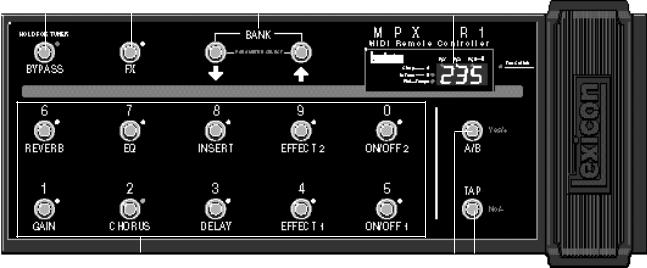
The Front Panel |
|
|
|||||||||
|
|
|
|
|
|
|
|
|
|
|||
|
|
FX |
|
|
|
|
|
|
||||
|
|
Toggles between Program and FX Modes. |
|
|
|
|
||||||
Display |
||||||||||||
|
|
LED off indicates Program Mode is active. |
|
|
||||||||
|
|
|
|
FS1, FS2 and FS3 LEDs light to indicate state of |
||||||||
|
|
LED on indicates FX Mode is active. |
|
|
||||||||
|
|
|
|
external foot switches. |
||||||||
|
|
|
|
|
|
|
|
|
|
|||
|
|
|
|
|
|
|
|
|
|
3-Digit Display indicates ID number of currently |
||
Bypass |
|
|
|
|
|
|
|
|||||
Assignable switch sends |
|
|
|
|
|
|
|
loaded program. |
||||
a MIDI Controller value |
|
|
|
|
|
|
|
Tempo LED flashes in time with current tempo rate |
||||
|
|
|
Bank/Parameter Select |
|
||||||||
BYPASS ON=127 |
|
|
|
|
when Tap is active. |
|||||||
|
|
|
Buttons increment and decrement program banks |
|
||||||||
BYPASS OFF=0 |
|
|
|
|
A/B LEDs light to indicate A/B function is active. |
|||||||
|
|
|
or select adjustable parameters for editing. Press- |
|
||||||||
When held, activates the |
|
|
|
|
||||||||
|
|
|
|
|
|
|||||||
|
|
|
ing and holding either button activates fast scrolling. |
|
|
|
||||||
MPX G2 Tuner. |
|
|
|
|
|
|
||||||
|
|
|
|
|
|
|
|
|
||||
|
|
|
|
|
|
|
|
|
|
|
|
|
|
|
|
|
|
|
|
|
|
|
Switches (0-9) |
|
|
|
|
|
|
|
|
|
Press to complete a Program Change message which |
|
A/B |
|
|
Programmable Pedal |
||||
consists of the current Bank number and the switch |
|
Assignable switch, when |
|
|
Operates as an assignable MIDI |
||||
number (0-9). In FX mode, switches can be pro- |
|
used with the MPX 1, acti- |
|
|
Continuous Controller. Toe |
||||
grammed to transmit any MIDI Controller, Clock com- |
|
vates a variable glide be- |
|
|
Switch allows patched effects to |
||||
mands, Relay settings or MIDI Program Change. |
|
tween patched parameters. |
|
|
be turned on and off. |
||||
Switches 0-9 are used for entering Program Change |
|
|
|
|
|
|
|
|
|
|
|
|
|
|
|
|
|||
selections in Direct Access Mode. |
|
|
|
|
|
|
|
|
|
|
|
|
|
Tap |
|
|
|||
|
|
|
|
|
|
||||
|
|
|
|
When Tempo LED is flashing, sets tempo. |
|||||
|
|
|
|
(Press two or more times in rhythm to establish |
|||||
|
|
|
|
tempo rate.) |
|
|
|||
|
|
|
|
|
|
|
|
|
|
1-2

Toe Switch
Assignable switch sends MIDI Controller value ON=127; OFF=0.
POWER
Use Lexicon MSA power adapter, or 9 VAC 1 amp equivalent. Jack is unused when powering the MPX R1 with the 7-pin DIN connector.
MIDI OUT/REMOTE
5-pin DIN connector for MIDI OUT
or
7-pin DIN connector for MIDI OUT and bidirectional MIDI remote (for use with MPX 1 or MPX G2).
IN
5-pin DIN connector receives MIDI data from other equipment.
THRU
5-pin DIN connector passes any MIDI data received without change.
Product Overview
The Rear Panel
Edit/Run
Toggle switch for entering Edit mode.
Foot Pedal
1/4" Tip/Ring/Sleeve phone jack provided for foot pedal with 10kΩ to 50kΩ impedance.
Relay |
|
Foot Switch |
1/4" Tip/Ring/Sleeve phone jack |
|
1/4" Tip/Ring/Sleeve phone |
software selectable as a momen- |
|
jack for as many as three |
tary or latching switch. |
|
independent footswitches. |
|
|
|
Foot Switch |
|
|
Foot Pedal
For control-voltage input, use a 1/4" stereo plug with Sleeve connected to ground, Tip connected to the control voltage, and Ring unconnected or shorted to ground..
Relay
1-3
MPX R1 Version 2 User Guide |
Lexicon |
Installation Notes
Power Requirements
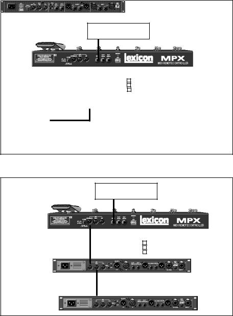
Connecting the MPX R1 to an MPX 1 or an MPX G2
Stand-alone
Configuration
Use Lexicon MSA power adapter, or 9 VAC 1 amp equivalent.
Relay
(Amp Channel Select)
|
|
|
|
|
|
|
|
|
|
|
|
|
|
|
|
|
|
|
|
|
Foot Pedal |
|
7-pin DIN |
|
|
|
|
|
|
|
||
|
|
|
|
|
Foot |
|
|
|
||
to AC Power |
|
Cable |
|
|
|
|
|
|
|
|
|
|
|
|
|
|
|
|
|||
|
|
|
|
|
Switch |
|
|
|
||
|
|
|
|
|
|
|
|
|
||
Source |
|
|
|
|
|
|
|
|
|
|
|
|
|
|
|
|
|
|
|
|
|
to Lexicon MSA Adapter
Connect a 7-pin DIN cable between the MPX (1 or G2) and the MPX R1. Connect the MPX (1 or G2) to the MSA adapter provided with the MPX R1.
Relay
(Amp Channel Select)
to Lexicon |
|
OUT |
|
|
|
|
|
|
|
|
|
|
|
|
|
|
|
||||
MSA Adapter |
|
|
|
|
|
|
|
|
|
Foot Pedal |
5-pin DIN Cable |
|
|
|
|
|
|
|
|||
|
|
|
|
|
Foot |
|
|
|
||
|
|
|
|
|
|
|
||||
|
IN |
|
|
|
|
Switch |
|
|
|
|
|
|
|
|
|
|
|
|
|
||
|
|
|
|
|
|
|
|
|||
MIDI Device 1
THRU
5-pin DIN Cable
IN
MIDI Device 2
1-4

The MPX R1 as a Dedicated MPX G2 Controller
2
When an MPX R1 is connected to an MPX G2, two-way communication is accomplished via MIDI System Exclusive messages. This allows immediate response by both units to actions on either front panel.
Connect the power adapter provided with the MPX R1 to the MPX G2 REMOTE POWER input jack and to a wall outlet.
Power up the MPX G2 and connect the 7-pin DIN cable provided with the MPX R1 between the MPX G2 rear panel IN/REMOTE jack and the MPX R1 MIDI OUT/REMOTE.
The MPX R1 will cycle through a power-up routine, lighting various LEDs, and then display Con. The MPX G2 will display Remote Connected. These messages indicate that proper bidirectional control has been established.
When the MPX G2 powers up, it will default to Program Mode. The MPX R1 should also power up in Program Mode. (FX button LED should be off.) In this mode, the MPX R1 sends MIDI Program Change and Bank Select messages to load MPX G2 programs.
These four switches and continuous controller transmit specific MIDI System Exclusive or Control Change messages regardless of the mode of operation.
In this mode, the state of A/B and the Tempo LED rate will automatically update to the state of the currently loaded program. For example, if you load a program set to 100 beats per minute (BPM), the MPX R1 will flash at 100 BPM, just as the MPX G2 does. If you then load a program set to 120 BPM, the Tempo LED on the MPX R1 will increase from 100 to 120 BPM when the new program loads. Pressing and holding the TAP button on the MPX R1 will display the current tempo in BPM on the R1 display.
The first two digits on the display indicate the bank number. The third digit indicates the program number. The BANK buttons select banks, and switches 0-9 select programs within the displayed bank. Programs are loaded whenever one of the numbered switches is pressed.
To load a new program within the same bank, press any of the numbered switches (0-9).
To select a program in a different bank, press the BANK buttons to step to the bank you want, or hold down either button to scroll through the numbers. The rightmost digit, which is reserved for program numbers, will turn off during bank selection. Once you have selected the desired bank, press the numbered switch to load the program number within that bank.
The MPX R1 as a
Dedicated MPX G2
Controller
MPX G2 and MPX R1
Connections
Working in
Program Mode
A/B Tap/Tempo, Bypass,
Toe and Pedal
Loading Programs
2-1
MPX R1 Version 2 User Guide |
Lexicon |
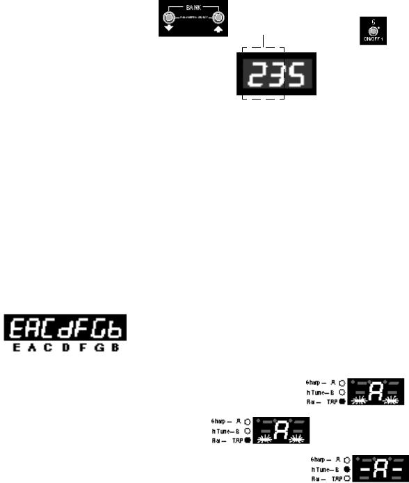
Use the BANK buttons to select a bank number. The first two digits on the display show your selection
— bank 23 in this example.
Press one of the switches numbered 0-9 to select a program within the selected bank. The third digit shows our selection — program 5.
Direct Access Mode
Tuner
You can also enter program numbers directly in Direct Access Mode. Press and hold the FX button until its LED begins blinking. The display will flash d-A to indicate that Direct Access Mode is active. Now you can select programs by directly entering their program numbers. For example, to load MPX G2 Program 135, press 1, then 3, then 5 on the MPX R1.
In this mode, the BANK buttons increment and decrement the program numbers in consecutive steps.
Press the FX button once to exit to FX Mode, twice to exit to Program Mode.
The MPX G2 tuner can also be viewed on the MPX R1. When the tuner is activated, the MPX G2 will display a letter corresponding to the closest semitone it detects (including sharp and flat notes) and indicate whether the note is sharp, flat, or in tune. The out-of-tune display segments will flash increasingly faster as a note reaches the correct pitch. The following example shows the display progression as a flat A is brought in tune.
Notes displayed when the MPX G2 Tuner is activated.
When the MPX G2 detects a note which is flat (A in this example), the lower display segments will flash and the Flat LED will light.
When the correct pitch is reached, the center display segments will light steadily, along with the Tune LED.
The display segments will flash faster as the note approaches the correct pitch.
2-2
The MPX R1 as a Dedicated MPX G2 Controller
A detected note which is sharp will be displayed in the same manner, with the upper display segments and the Sharp LED used as indicators.
When a note is detected as a complete half-tone step up from a natural note, the
LED at the upper right of the displayed letter identifies it as (in this example) an
A#.
An A# is displayed as an in-tune note, with the # indicator lit.
For more information on Tuner functionality, please refer to the MPX G2 User
Guide.
FX Mode allows you to turn on and off any of the active effects in the current FX Mode program. To access FX Mode, press the MPX R1 FX button. The LED next to
the button will light to indicate you are in FX Mode.
The FX LED is lit when FX Mode is active.
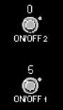
Buttons 1-4 and 6-9 bring MPX G2 effects (Gain, Chorus, Delay, Effect 1, Reverb, EQ, Insert and Effect 2) in and out of bypass. The LED for each button indicates the current state of the MPX G2 Effect:
Green |
= MPX G2 Effect on |
|
Red |
= MPX G2 |
Effect bypassed, but available |
Off |
= MPX G2 |
Effect unavailable |
As in Program mode, the R1 will update to match the current MPX G2 A/B, Tempo and Bypass states of the currently loaded program. If you press any of these controls on the MPX G2, or if you load a new program from the MPX 1, the R1 will update accordingly.
2-3
MPX R1 Version 2 User Guide |
Lexicon |
Relay State You can also control the MPX R1 4-state relay in FX mode.
Programming
A relay is simply an electronic switch that can tell a circuit (typically an amp's channel-switching scheme, or reverb and tremolo status) what "state" to go to. Manufacturers use different schemes, or "logic states" to accomplish similar tasks, and the MPX R1 can be programmed to satisfy these requirements, allowing you, for example, to use your MPX R1 as a replacement for your amp's channel-switching footswitch.
Storing a Relay State
The relay state can be stored with each MIDI Program Change message. To do this, select the desired MIDI program on the MPX R1 and press the MPX R1 FX button to enter FX mode
The relay states are assigned to the following buttons as factory defaults.
ON/OFF 1 |
= |
Relay state 1 |
ON/OFF 2 |
= |
Relay state 2 |
Press the button assigned to the desired relay state and hold the button down for two seconds. The relay state (for example, CH1) will flash once on the MPX R1 display to indicate that it has been stored with the program.
Clearing a Relay State
To clear a relay state, press and hold any button not assigned to a relay channel. Hold this button down for two seconds until – – – flashes once on the display to indicate the relay state for that program has been removed.
Removing Relay Settings for All Programs
To reset all of the relay settings to Not Assigned, go to Edit: Program Mode (Press and hold the rear panel EDIT/RUN switch until Edt appears on the display.) Use the BANK/Parameter Select buttons to select the Relay Initialize parameter (rEi). Press Yes/+ to reset all of the relays. Note that the relays stay in their last state (based on the last physical button press) until a button is pressed to assign a different state. Briefly press and release the rear panel EDIT/ RUN switch to exit Edit Mode.
2-4
 Loading...