


MC-8
MC-8 Digital Controller
User Guide
IMPORTANT SAFETY INSTRUCTIONS
1. Read these instructions.
2. Keep these instructions.
3. Heed all warnings.
4. Follow all instructions.
5. Do not use this apparatus near water.
6. Clean only with a dry cloth.
7. Do not block any ventilation openings. Install in
accordance with the manufacturer’s instructions.
8. Do not install near any heat sources such as radiators, heat registers, stoves, or another apparatus
(including amplifiers) that produces heat.
9. Do not defeat the safety purpose of the polarized or
grounding-type plug. A polarized plug has two
blades with one wider than the other. A groundingtype plug has two blades and a third grounding
prong. The wide blade or the third prong are provided for your safety. If the provided plug does not
fit into your outlet, consult an electrician for
replacement of the obsolete outlet.
10. Protect the power cord from being walked on or
pinched particularly at plugs, convenience
receptacles, and the point where they exit from
the apparatus.
11. Only use attachments/accessories specified by the
manufacturer.
12. Use only with the cart, stand, tripod, bracket, or
table specified by the manufacturer, or sold with the
apparatus. When a cart is used, use caution when
moving the cart/apparatus combination to avoid
injury from tip-over.
13. Unplug this apparatus during lightning storms or
when unused for long periods of time.
14. Refer all servicing to qualified service personnel.
Servicing is required when the apparatus has been
damaged in any way, such as when a power-supply
cord or plug is damaged, liquid has been spilled or
objects have fallen into the apparatus, the apparatus has been exposed to rain or moisture, does not
operate normally, or has been dropped.
• Refer to the manufacturer’s operating instructions
for power requirements. Be advised that different
operating voltages may require the use of different
line cord and/or attachment plug.
• Do not install the unit in an unventilated rack, or
directly above heat-producing equipment such as
power amplifiers. Observe the maximum ambient
operating temperature listed in the product specification.
• Never attach audio power amplifier outputs directly
to any of the unit’s connectors.
This equipment has been tested and found to comply
with the limits for a Class B digital device, pursuant to
Part 15 of FCC Rules. These limits are designed to
provide reasonable protection against harmful interference in a residential installation. This equipment
generates, uses, and radiates radio frequency energy
and, if not installed and used in accordance with the
instructions, may cause harmful interference to radio
or television reception, which can be determined by
turning the equipment off and on. The user is encouraged to try to correct the interference by one or more
of the following measures:
• Re-orient or relocate the receiving antenna.
• Increase the separation between the equipment
and the receiver.
• Connect the equipment into an outlet on a circuit
different from that to which the receiver is connected.
• Consult the dealer or an experienced radio/television technician for help.
WARNING
To reduce the risk of fire or electric
shock, do not expose this apparatus to
rain or moisture. Do not place objects
containing liquid, such as vases, on this
apparatus.

Lexicon Inc.
3 Oak Park
Bedford, MA 01730-1413 USA
Tel 781-280-0300
Fax 781-280-0490
www.harmanspecialtygroup.com
Manufactured under license from Dolby Laboratories. Dolby®, Pro Logic®, and the double-D symbol are a registered trademarks of
Dolby Laboratories. Surround EX is a trademark of Dolby Laboratories.
Manufactured under license from Digital Theater Systems, Inc. U.S. Pat. No’s 5,451,942; 5,956,674; 5,974,380; 5,978,762;
6,226,616; 6,487,535 and other U.S. and world-wide patents issued and pending. DTS, DTS-ES, Neo:6, and DTS 96/24 are
trademarks of Digital Theater Systems, Inc. Copyright 1996, 2003 Digital Theater Systems, Inc. All rights reserved.
Manufactured under license from THX Ltd. U.S. patent numbers 5, 043,970; 5,189,703 and/or 5,222,059. European patent number
0323830. Other U.S. and foreign patents pending. Ultra2 and THX are trademarks or registered trademarks of THX Ltd. Surround EX
is a trademark of Dolby Laboratories. Used under authorization.
SACD is a trademark of Sony Electronics, Inc.
Customer Service
Telephone: 781-280-0300
Sales Fax: 781-280-0495
Service Fax: 781-280-0499
Part No. 070-15481 | Rev 1 | 08/05
SHARC is a Trademark of Analog Devices, Inc.
Lexicon, Logic 7 and the L7 logo are registered trademarks of Harman International Industries, Inc. U.S. Patent Nos. D454,553;
D454,860; 5,796,844; 5,870,480 and other worldwide patents issued and pending. Lexicon LIVE is a trademark of Harman International Industries, Inc.
© 2005 Harman International Industries, Incorporated. All rights reserved.
This document should not be construed as a commitment on the part of Harman Specialty Group. The information it contains is
subject to change without notice. Harman Specialty Group assumes no responsibility for errors that may appear within this
document.
Introduction Lexicon
DOCUMENTATION CONVENTIONS
This document contains general safety, installation and operation instructions for the MC-8 and MC-8 Balanced Digital Controllers. It is important to read this user guide before attempting to use the product. Pay particular attention to safety instructions.
The following symbols are used in the document:
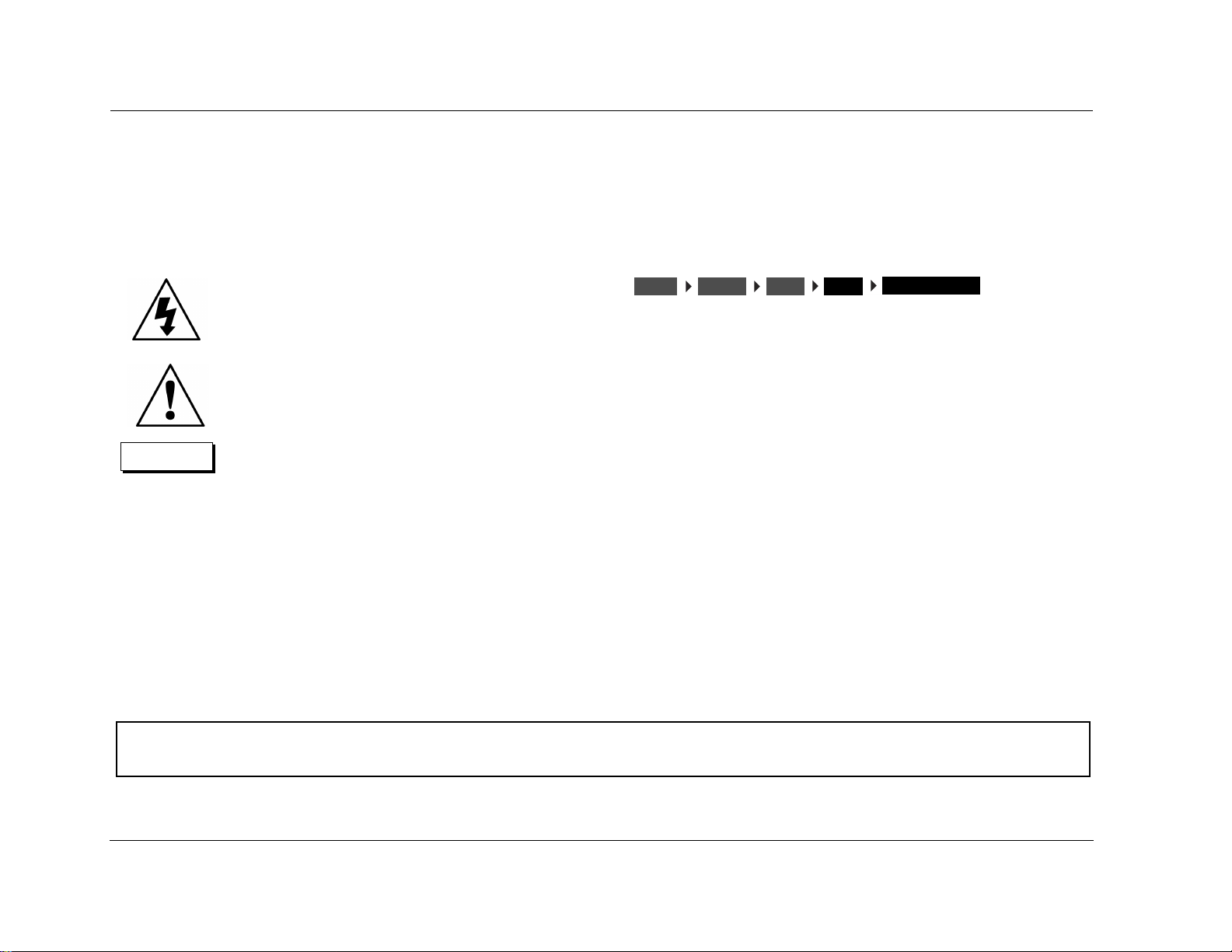
WARNING
CAUTION!
Note:
Appears on the component to indicate the presence of uninsulated, dangerous voltage inside
the enclosu
constitute a risk of shock.
Appears on the component to indicate important operating and maintenance instructions in
the accompanying literature.
Calls attention to a procedure, practice, condition or the like that, if not correctly performed
or adhered to, could result in injury or death.
Calls attention to a procedure, practice, condition or the like that, if not correctly performed
or adhered to, could result in damage or
destruction to part or all of the product.
Calls attention to information that is essential to
highlight.
re – voltage that may be sufficient to
INPUTSSETUP
Represents a menu path. The menu items in gray boxes must be
selected with the remote control Menu arrow to access the
menu or menu item in the black box. For example, the SETUP,
INPUTS, and DVD1 menu items must be selected to open the
DVD1 INPUT SETUP menu.
The DVD1 INPUT SETUP menu is used here as an example and will
continue to be used as an example throughout this document.
Whenever it appears, any other INPUT SETUP menu may be substituted. Likewise, whenever the DVD1 input appears as a step in a
menu path, any other input may be substituted.
DVD1
NAME
EDIT INPUT NAME
This document uses the term MC-8 to refer to both the MC-8 and MC-8 Balanced Digital Controllers unless otherwise specified.
This document uses the term DTS-(ES) to indicate that DTS-ES encoding may or may not be present in the input source.
ii

MC-8 Introduction
Table of Contents
Documentation Conventions........................................................ ii
Getting Started
About the MC-8........................................................................1-2
Highlights ............................................................................. 1-4
Product Registration ..................................................................1-5
Installation Considerations.........................................................1-5
Remote Control Battery Installation ...........................................1-6
Basic Operation
Front-Panel Overview ................................................................2-2
Rear-Panel Overview..................................................................2-6
Remote Control Overview .......................................................2-10
Operation Considerations .................................................... 2-10
MAIN Menu ........................................................................ 2-10
Menu Navigation ................................................................ 2-10
Menu Item Selection ........................................................... 2-11
Command Bank Activation .................................................. 2-13
Command Matrix ............................................................... 2-14
Understanding the Zones ........................................................ 2-18
Two-Line Status.......................................................................2-19
STATUS Menus........................................................................2-19
STATUS Menu Descriptions ................................................. 2-20
STATUS Menu Parameter Descriptions ................................ 2-24
STATUS Menu Level Meters.....................................................2-25
Setup
Setup ........................................................................................3-2
Input Setup ............................................................................... 3-4
Changing Input Names ......................................................... 3-5
Assigning Audio and Video Input Connectors ........................ 3-7
Selecting Preferred Listening Modes .................................... 3-12
Configuring Advanced Input Settings .................................. 3-17
INPUT SELECT Parameter Settings ....................................... 3-19
ZONE2 in Parameter Settings .............................................. 3-21
Speaker Setup .........................................................................3-22
Setting Crossover Points ...................................................... 3-22
Speaker Setup Parameters ................................................... 3-26
Calibrating Speaker Distances and Output Levels .................... 3-33
Speaker Calibration Parameters ........................................... 3-33
Automatic Calibration ......................................................... 3-35
Manual Calibration ............................................................. 3-52
Rear-Panel Configuration......................................................... 3-59
Display Setup .......................................................................... 3-61
Volume Control Setup............................................................. 3-66
Trigger Setup .......................................................................... 3-67
Lock Options........................................................................... 3-69
LIVE! CALIBRATION ................................................................. 3-70
Audio Controls
Audio Controls .......................................................................... 4-2
Mode Adjust
Mode Adjust ............................................................................. 5-2
Listening Mode Activation.........................................................5-2
Preferred Listening Mode Selection ....................................... 5-3
MODE and BUTTONS .................................................. 5-3
Listening MODE SELECTION BUTTONS ................................. 5-3
Listening Mode Descriptions ..................................................... 5-4
Listening Mode Menu Option and Parameter Descriptions...... 5-34
Mode – Parameter Relationships.............................................. 5-42
Troubleshooting and Maintenance
Troubleshooting........................................................................ 6-2
iii

Introduction Lexicon
Routine Maintenance.................................................................6-4
Restoring Factory-Default Settings .............................................6-4
Appendix
Specifications.............................................................................A-2
Declaration of Conformity .........................................................A-4
Menu Tree.................................................................................A-5
Installation Worksheet .............................................................A-20
iv

1
Getting Started
About the MC-8 ......................................................................... 1-2
Highlights .................................................................................................1-4
Product Registration................................................................... 1-5
Installation Considerations.......................................................... 1-5
Remote Control Battery Installation ............................................ 1-6

Getting Started Lexicon
ABOUT THE MC-8
Thank you for purchasing the MC-8 Digital Controller, an 8-channel
audio and video control center with independent zone monitoring
that provides control of audio and video source selection in two
zones at the same time. The MC-8 includes eight configurable
inputs, each of which can be assigned to its eight digital audio,
eight analog audio, five composite video, five S-Video, or three
component video input connectors. The analog connectors can be
configured for up to two 5.1-channel sources. In addition, the
MC-8 Balanced offers balanced analog audio output connectors for
all Main Zone and Zone 2 channels.
Inside and out, the MC-8 is designed for possible future developments. The rear panel houses one RS-232 connector capable of
performing configuration downloads and flash memory software
upgrades, and another capable of supporting future developments.
The rear panel also includes two removable access panels to accommodate connectors for emerging technologies.
More than just an audio and video control center, the MC-8
features the latest version of Lexicon’s critically acclaimed LOGIC 7
decoding, which derives 7.1-channel output from stereo, and 5.1and 6.1-channel sources. Unlike other decoders, LOGIC 7 is
compatible with all input sources and requires no special encoding.
Because the improvement it provides is clearly audible, LOGIC 7
decoding is widely regarded as the finest available.
The MC-8 also offers LIVE! (Lexicon Intelligent Variable
Environment), designed to transform the way your listening room
sounds with the live sound that is created within the room by the
occupants of the room. LIVE! does not (nor is it meant to) work with
prerecorded material. LIVE! provides a realistic illusion of a larger,
more reverberant listening space–ideal for musicians wishing to
practice or perform with the sound of a larger venue.
LIVE! is a unique, sophisticated reverberation system that uses a
combination of microphones and digital signal processing (DSP) to
enhance a room’s acoustics and create the illusion of a much larger
space. When you engage in normal conversation, it seems as if you
are in a large room. When you practice or perform with a musical
instrument, it seems as if you are in a concert hall. Choose from one
of three customizable presets to create an ambience to liven up a
party or amaze your friends.
In addition to LOGIC 7, the MC-8 offers THX Ultra2 certification,
which guarantees that the MC-8 meets the highest THX®
specifications.
With four floating-point SHARC™ digital signal processing (DSP)
engines, the MC-8 boasts enormous processing power. These
powerful processors perform custom Lexicon processing such as
LOGIC 7 decoding, bass enhancement, dialogue enhancement,
auto azimuth, five-speaker enhancement, bass management, highprecision digital crossovers and audio controls. These features are
®
available at sample rates of up to 96kHz, with 24-bit resolution to
retain top performance from all sources. In addition, a fifth DSP
engine is dedicated to decoding multichannel compressed audio
sources.
The MC-8 is one of the most advanced audio and video control
centers available. High-precision 24-bit/96kHz A/D converters can
be used to convert stereo analog audio input signals to digital
signals, allowing the MC-8 to provide the benefits of precise digital
signal processing without sacrificing signal integrity. Alternatively,
stereo analog signals can bypass A/D conversion and internal
processing, following a pure signal path directly to the output
connectors.
1-2

MC-8 Getting Started
Digital audio input signals are processed through a two-stage phase
lock loop for extremely low intrinsic jitter and high rejection.
Lexicon’s proprietary auto azimuth technology corrects timing and
level imbalances in stereo sources, ensuring exceptionally accurate
playback of surround-encoded sources. A digital audio pass
through output is available for recording digital signals with a CD
recorder or a similar component.
Complementing its audio performance, the MC-8 features two
broadcast-quality video switchers. An ultrawide-bandwidth
component video switcher accepts analog component or RGB
video signals, while a composite and S-Video switcher accepts high-
quality NTSC, PAL or SECAM video signals. The component video
switcher can pass high-definition TV (HDTV) signals, and standarddefinition (SD) TV signals. Both switchers are designed to pass video
signals without alteration or degradation.
Built to professional standards, the MC-8 is designed to serve as the
control center in any high-quality home theater. Even the most
demanding enthusiast will be impressed with its unique combination of power, performance, flexibility and technological
sophistication. With extensive expansion capabilities, the MC-8
represents a solid investment that will retain its value in the face of
rapidly emerging technologies.
1-3

Getting Started Lexicon
HIGHLIGHTS
• Eight channels
• Eight configurable inputs
• Two independent zones
• Four S/PDIF coaxial and four S/PDIF
optical digital audio input connectors
• Up to two 5.1-channel analog audio input
connectors
• Analog bypass option for stereo audio
input connectors
• Auto switching between digital and
analog audio input connectors
• 24-Bit/192kHz D/A converters for all
audio channels
• Automatic and manual calibration of
speaker distances and output levels
• Three component video input
connectors with full HDTV compatibility
•Five S-Video input connectors
• Five composite video input connectors
• Broadcast-quality video switching
• Four 32-bit DSP engines
• Separate DSP engine for decoding
compressed audio sources
• LOGIC 7 decoding
• LIVE! (Lexicon Intelligent Variable
Environment)
• Dolby Digital Surround EX, Dolby Pro
Logic IIx, and Dolby Pro Logic decoding
• DTS 96/24, DTS NEO:6, and DTS-ES
(discrete and matrix) decoding
• THX Ultra2 and THX Surround EX
decoding
• THX Ultra2 certification
• RS-232 control
• Digital audio output connector
• Two trigger output connectors
• Rear-panel IR input connector
• Four microphone input connectors
• Two internal expansion slots
• Removable access panel
• Balanced audio output connectors for all
Main Zone and Zone 2 channels (MC-8
Balanced only)
• Flash memory software upgrade
capabilities
• Optional 19-inch rack-mount kit
1-4

MC-8 Getting Started
PRODUCT REGISTRATION
Please register the MC-8 Digital Controller within 15 days of
purchase. Register online at www.lexicon.com or complete and
return the product registration card attached to the back cover of
this user guide. Retain the sales receipt as proof of warranty
coverage.
INSTALLATION CONSIDERATIONS
The MC-8 requires special care during installation to ensure optimal
performance. Pay particular attention to instructions below and to
other precautions that appear throughout this user guide.
DO install the MC-8 on a solid, flat, level surface such as a table or
shelf. The MC-8 can also be installed in a standard 19-inch
equipment rack using an optional rack-mount kit available from an
authorized Lexicon dealer.
DO select a dry, well-ventilated location out of direct sunlight.
DO NOT expose the MC-8 to high temperatures, humidity, steam,
smoke, dampness or excessive dust. Avoid installing the MC-8 near
radiators and other heat-producing appliances.
DO NOT place the MC-8 on a windowsill or any location exposed
to direct sunlight.
DO NOT obstruct the front-panel IR receiver window. The remote
control must be in line of sight with the IR receiver for proper
operation.
DO NOT install the MC-8 on a surface that is unstable or unable to
support all four feet.
DO NOT stack the MC-8 directly above heat-producing equipment
such as a power amplifier.
CAUTION!
Before moving the MC-8, power the unit off using the
rear-panel power switch and unplug the power cord from
the wall outlet.
DO NOT install the MC-8 near unshielded TV or FM antennas, cable
TV decoders, or other RF-emitting devices that might cause
interference.
DO NOT place the MC-8 on a thick rug or carpet, or cover the
MC-8 with a cloth, as this might prevent proper cooling.
1-5
Getting Started Lexicon
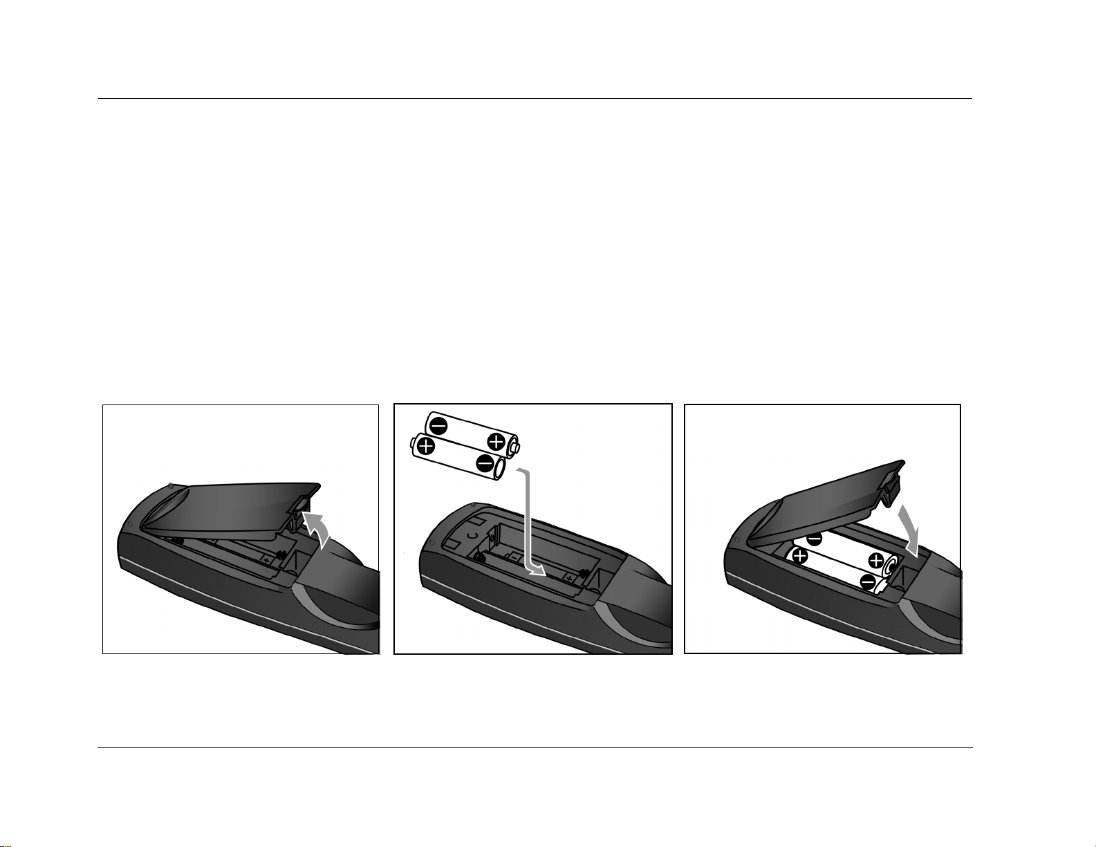
REMOTE CONTROL BATTERY INSTALLATION
The remote control requires two AA batteries. The batteries should be replaced as needed. Alkaline batteries, which last longer without leaking,
are recommended. When battery power is low, the remote control enters a low-voltage condition, preventing it from operating the MC-8.
When this occurs, replace the batteries. Normal operation will resume when new batteries are installed.
To replace the remote control batteries:
1. Locate the battery compartment on the back of the remote control. Press the tab and lift the cover away from the remote control.
2. Remove old batteries (if applicable).
3. Observing the proper polarity, insert two AA batteries.
4. Align the cover over the battery compartment and gently press down until it snaps back into place.
5. Dispose of the old batteries (if applicable).
1-6

2
Basic Operation
Front Panel Overview ................................................................. 2-2
Rear Panel Overview................................................................... 2-6
Remote Control Overview ........................................................ 2-10
Operation Considerations........................................................................ 2-10
MAIN Menu ............................................................................................ 2-10
Menu Navigation ................................................................................... 2-10
Menu Item Selection ............................................................................... 2-11
Command Bank Activation...................................................................... 2-13
Command Matrix ................................................................................... 2-14
Understanding the Zones ......................................................... 2-18
Two-Line Status........................................................................ 2-19
STATUS Menus......................................................................... 2-19
STATUS Menu Descriptions ..................................................................... 2-20
STATUS Menu Parameter Descriptions .................................................... 2-24
STATUS Menu Level Meters...................................................... 2-25
Basic Operation Lexicon
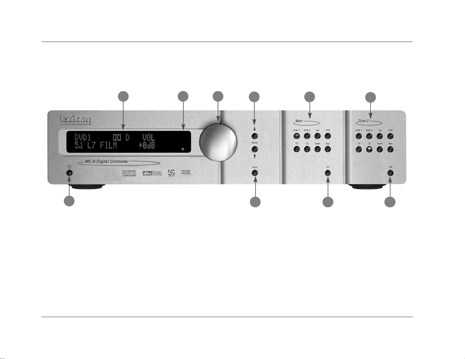
FRONT-PANEL OVERVIEW
The MC-8 is shown below. The MC-8 Balanced is shown on page 2-4. The front panels are identical, except the MC-8 Balanced has a larger
chassis. The numbers in the front-panel illustrations correspond with the numbered items in the text.
2
3
1
1 STANDBY BUTTON
Use the Standby button to activate or deactivate standby mode.
The Standby button performs no function when the MC-8 rearpanel power switch is powered off. When standby mode is deactivated, all MC-8 zones that were active during the last session are
reactivated. The red standby button LED lights whenever standby
mode is activated.
4
5
6
7
8
9
10
2 FRONT-PANEL DISPLAY
Use the front-panel display to view the current input, listening
mode, input source and volume level. The 2 x 20 character display
also functions as a display for messages and menus.
Note:
Power is still supplied to the MC-8 when standby mode is activated.
2-2
MC-8 Basic Operation
3 IR RECEIVER
The IR receiver receives infrared commands from the MC-8 remote
control. There are three associated LEDs.
• The amber LED blinks when a remote control command is
received.
• The red LED lights when the A/D converters are overloading.
• The blue LED lights when the MC-8 is powered on and
activated – even if the FRONT PANEL DISPLAY menu STATUS
parameter is set to ALWAYS OFF.
Amber LEDRed LED
Blue LED
4 VOLUME KNOB
Use the volume knob to adjust volume level in the Main Zone or Zone 2.
To adjust the Main Zone volume level:
Rotate the volume knob clockwise to increase
or counterclockwise to decrease volume level
in 1dB increments. A horizontal bar graph
indicating the current Main Zone volume level is displayed in the
on-screen and front-panel displays. The Main Zone volume range is
–80 to +12dB.
VOLUME -34db
To adjust the Zone 2 volume level:
1. Press and hold the front-panel Zone 2 input selection button
that corresponds with the current input source. For instance, if
the current input source is using the DVD1 input, press and
hold the DVD1 input selection button.
2. While holding the selected Zone 2 input
ZONE 2 VOLUME -34db
selection button, rotate the volume knob
clockwise to increase or counterclockwise
to decrease volume level in 1dB increments. The corresponding
horizontal graph shown here appears in the on-screen and frontpanel displays. This graph illustrates the position at which the
current Zone 2 volume level falls within the –80 to +12dB
volume range.
3. Release the selected Zone 2 input selection button when Zone 2
volume level has been set.
Note:
Remote control input selection buttons cannot be used to select Zone 2
level adjustment, even if the Zone 2 command bank is activated.
5 MODE and BUTTONS
Use the Mode buttons to scroll to the previous () and next ()
available listening mode. Scrolling occurs in the order shown in the
MODE ADJUST menu. Refer to the Listening Mode Activation section
that begins on page 5-2 for more information.
2-3
Basic Operation Lexicon
FRONT-PANEL OVERVIEW (continued)
The MC-8 Balanced, shown below, has a larger chassis than the MC-8, shown on page 2-2. Otherwise, they are identical. The numbers in the
front-panel illustrations correspond with the numbered items in the text.
1
6 MUTE BUTTON
3
5
6
742
8
9
10
Mutes or restores the MC-8 Main Zone volume to its original level.
Press the Mute button to mute volume level; “MUTE ON” appears in
the on-screen and front-panel displays. Press the Mute button again
to restore the volume to its original level. The VOLUME CONTROL
SETUP and MUTE LEVEL parameter can be used to set mute levels.
2-4
Mute may be activated automatically or manually. For example, the
MC-8 briefly activates mute when changing input sources or
listening modes. The amber Mute button LED lights whenever
mute is activated.

MC-8 Basic Operation
7 MAIN ZONE INPUT SELECTION BUTTONS
Selects the corresponding input in the Main Zone. When an input is
selected, a blue LED lights on the corresponding input selection
button. When the Main Zone is deactivated, pressing a Main Zone
input selection button activates the Main Zone and selects the
corresponding input. Zone 2 remains deactivated until a Zone 2
input is selected.
8 MAIN ZONE OFF BUTTON
Deactivates the Main Zone.
9 ZONE 2 INPUT SELECTION BUTTONS
Selects the corresponding input in Zone 2. When an input is
selected, an amber LED lights on the corresponding input selection
button. When Zone 2 is deactivated, pressing a Zone 2 input
selection button activates Zone 2 and selects the corresponding
input. The Main Zone remains deactivated until a Main Zone input
is selected.
10 ZONE 2 OFF BUTTON
Deactivates Zone 2.
2-5
Basic Operation Lexicon
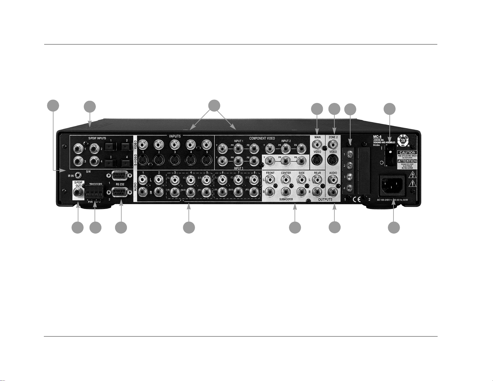
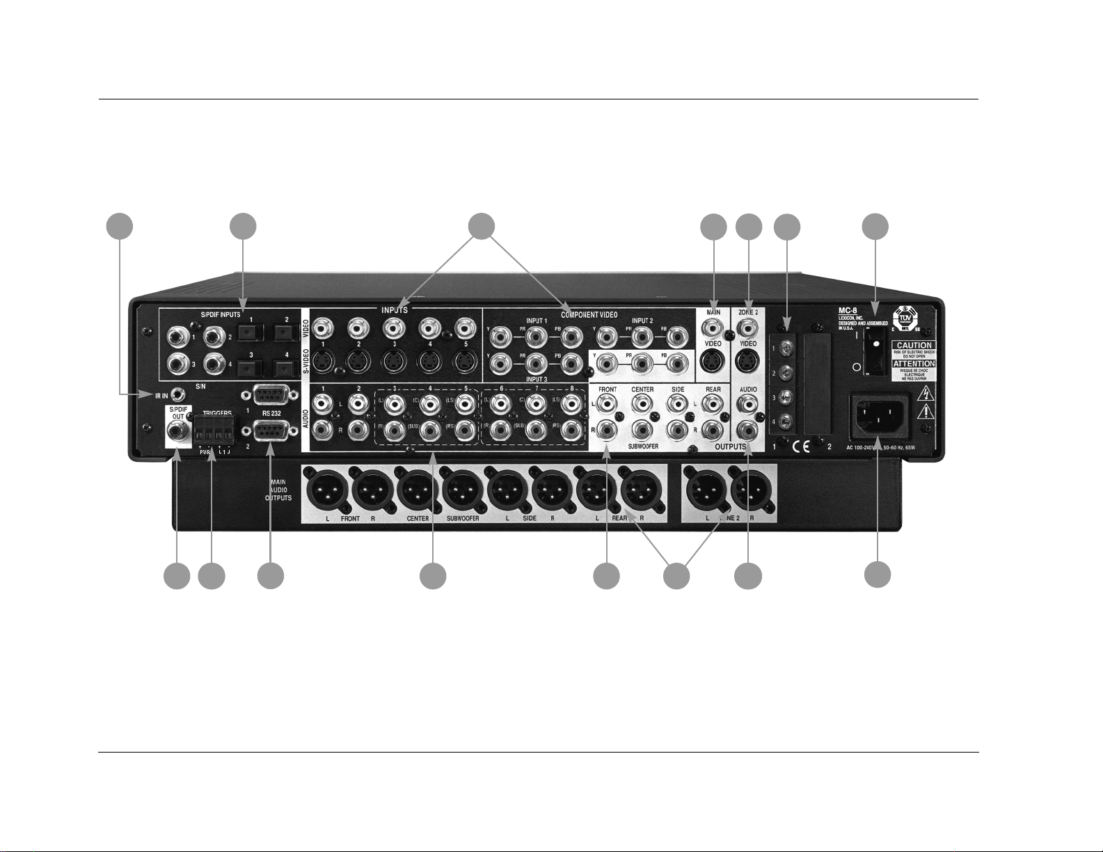
REAR-PANEL OVERVIEW
The MC-8 is shown below. The MC-8 Balanced, shown on page 2-8, includes balanced audio output connectors for the Main Zone and Zone
2. Otherwise, both models are identical. The numbers in the rear-panel illustrations correspond with the numbered items in the text.
1
2
1314
12
11
3
10
4
6
5
9
7
8
CAUTION! Never make or break connections to the MC-8 unless the MC-8 and all associated components are powered off.
1 IR IN CONNECTOR
Accepts input of IR signals from infrared distribution equipment.
One 3.5mm jack that accepts a stereo plug (Tip/Ring/Sleeve
connection) or mono plug (Tip/Sleeve connection) is available.
2 DIGITAL AUDIO INPUT CONNECTORS
(S/PDIF)
Provide digital audio input in the Main Zone and Zone 2. Four S/PDIF
coaxial and four S/PDIF optical input connectors are available.
Connectors are compatible with PCM (44.1, 48, 88.2 and 96kHz),
Dolby Digital and DTS(-ES) sources.
2-6

MC-8 Basic Operation
3 VIDEO INPUT CONNECTORS
Provide video input in the Main Zone and Zone 2. Five composite
video connectors labeled Video 1 to 5, five S-Video connectors
labeled S-Video 1 to 5, and three component video connectors
labeled 1 to 3 are available. The component video connectors are
not available for Zone 2.
4 MAIN ZONE VIDEO OUTPUT CONNECTORS
Provide video output in the Main Zone. One composite video
connector, one S-Video connector and one component video
connector (RCA) are available.
Note:
• Composite video output connectors are available when a composite
or S-Video source is present.
• S-Video output connectors are available when an S-Video source is
present.
• Component video output connectors are available when a
component video source is present.
5 ZONE 2 VIDEO OUTPUT CONNECTORS
Provide video output in Zone 2. One composite video connector
and one S-Video connector are available. Alternatively, these
connectors can be used to connect a video recording device.
6 MICROPHONE INPUT CONNECTORS
Provide microphone input for speaker distance and output level
calibration. Additionally, inputs 1 (left) and 2 (right) are used when
LIVE! is active. Four 3.5mm Tip/Ring/Sleeve connectors are available.
7 POWER SWITCH
Use the Power switch to power the MC-8 on or off. The I and O
positions represent “on” and “off” status, respectively. When the
MC-8 is powered on, the front-panel Standby button or remote
control On button can be used to activate and deactivate standby
mode. When the MC-8 is powered off, standby mode is not
available.
8 AC INPUT CONNECTOR
Provides power to the MC-8 through the supplied power cord
(3-wire, 10-amp, IEC 320).
9 ZONE 2 AUDIO OUTPUT CONNECTORS
Provide analog audio output in Zone 2. Two connectors labeled Audio
are available. Alternatively, these connectors can be used to connect
a recording device. When the Zone 2 audio output connectors are
sent to a recording device, it is recommended that you set the
VOLUME CONTROL SETUP menu ZONE PWR ON parameter to
+0dB to achieve appropriate recording levels. The Zone 2 audio
output connectors provide variable output levels. Adjusting Zone 2
volume level will affect the recording.
2-7
Basic Operation Lexicon
REAR-PANEL OVERVIEW (continued)
The MC-8 is shown on page 2-6. The MC-8 Balanced, shown below, includes balanced analog audio output connectors for the Main Zone and Zone 2.
Otherwise, both models are identical. The numbers in the rear-panel illustrations correspond with the numbered items in the text.
1
14
2
13 12
11
3
10
4
15
6
5
9
7
8
CAUTION! Never make or break connections to the MC-8 unless the MC-8 and all associated components are powered off.
2-8

MC-8 Basic Operation
10 MAIN ZONE AUDIO OUTPUT CONNECTORS
Provide analog audio output in the Main Zone. Eight connectors–labeled
Front L/R, Center, Subwoofer, Side L/R and Rear L/R–are available.
11 ANALOG AUDIO INPUT CONNECTORS
Provide analog audio input in the Main Zone and Zone 2. Eight
stereo analog audio input connectors labeled 1 to 8 are available.
Connectors labeled 3, 4 and 5, and 6, 7 and 8 can be configured as
5.1-channel connectors.
When a 5.1-channel analog audio source is present in the Main Zone,
input signals are sent to the Main Zone audio output connectors, as
indicated in the table below. When a 5.1-channel analog source is
present in the Main Zone and the INPUT SETUP menu ZONE2 IN
parameter is set to DMIX, only the (L) and (R) input signals are sent
to the Zone 2 audio output connectors.
Input Connector Output Connector
(L) & (R) Front L/R
(C) Center
(SUB) Subwoofer
(LS) & (RS) Side L/R and Rear L/R
12 RS-232 CONNECTORS
The RS-232 serial connector (1) is used to perform configuration
downloads and flash memory software upgrades. The RS-232
connector (2) is capable of supporting future developments.
13 TRIGGER OUTPUT CONNECTORS
Provide 12V DC output to control connected components. Two
trigger output connectors are available on a removable terminal block.
The PWR connector – the power trigger output connector – is not
configurable. It is activated when the MC-8 is activated, and deactivated when the MC-8 is deactivated. The trigger output connector (1)
can be configured for remote or program operation.
14 DIGITAL AUDIO OUTPUT CONNECTOR (S/PDIF)
Provides digital audio output in Zone 2. One S/PDIF coaxial
connector is available.
15 BALANCED AUDIO OUTPUT CONNECTORS
(MC-8 BALANCED)
Provide balanced analog audio output in the Main Zone and Zone
2. Eight connectors–labeled Front L/R, Center, Subwoofer, Side L/R
and Rear L/R–are available in the Main Zone. Two connectors–
labeled Zone 2 L/R–are available in Zone 2.
2-9

Basic Operation Lexicon
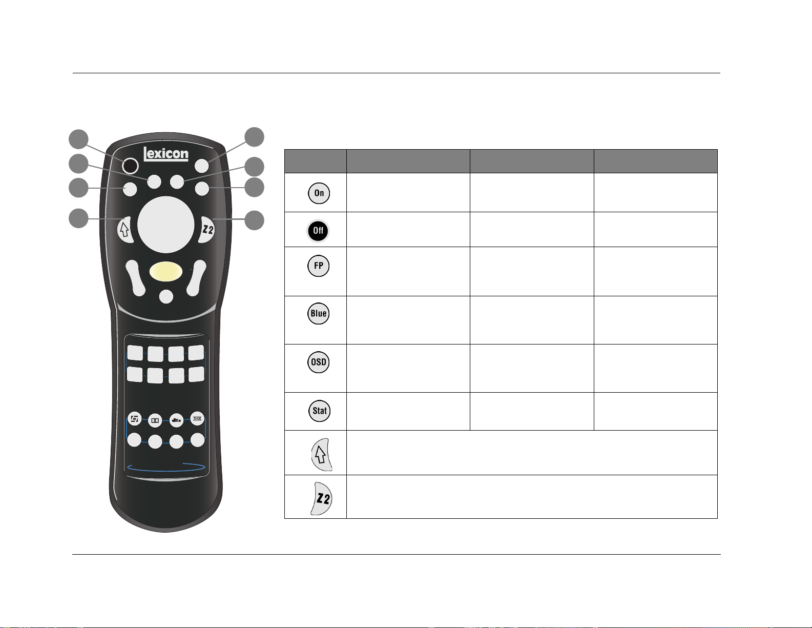
REMOTE CONTROL OVERVIEW
The MC-8 remote control provides full operation of the MC-8,
including commands, such as menu navigation, that are not available
from the front panel. The command matrix, beginning on page 2-14,
indicates the commands that the remote control buttons perform
when each command bank is active. The numbered items in the
matrix correspond with the remote control illustrations.
OPERATION CONSIDERATIONS
The following factors can improve or impede remote control
operation.
Note the following before operating the MC-8 remote control:
• The remote control must be in line of sight with the front- panel
IR receiver. Eliminate obstructions between the remote control
and the IR receiver. The remote control may become unreliable
if strong sunlight or fluorescent light shines on the IR receiver.
• For optimal performance, position the remote control at a
30-degree angle no more than 17 feet (5m) from the MC-8.
Placing the MC-8 inside a smoked glass cabinet will reduce the
remote control range.
• Remote controllers for different components can interfere with
one another. Avoid using remote controls for different components at the same time.
• Remote control batteries should be replaced as needed.
MAIN MENU
MAIN MENU
MODE ADJUST
AUDIO CONTROLS
SETUP
The MAIN MENU represents the beginning of
the menu structure. Use the MAIN MENU to
open the three main menu branches: MODE
ADJUST, AUDIO CONTROLS and SETUP.
MENU NAVIGATION
Use the remote control arrow buttons to navigate the extensive
menu structure shown in the Appendix. The table on the next page
indicates the navigation commands that the remote control
buttons perform when the Main Zone command bank is activated.
2-10
MC-8 Basic Operation
MENU ITEM SELECTION
Use the remote control Menu arrows to navigate menus and to select menu items.
Arrow Navigation Functions
To select a menu item on the open menu:
1. Press the remote control and arrow buttons to highlight the
desired menu item.
2. When the desired menu item is highlighted, press the arrow
button to select the highlighted item. If an option is selected,
another menu opens. If a parameter is selected, a parameter
drop-down menu or horizontal graph opens.
• When a menu is open, press the arrow button to select the highlighted menu item.
• When no menus are open, press the arrow button to open the MAIN MENU.
• When a menu is open, press the arrow button to close the menu and, in most cases, open the previous menu. Subsequent presses continue to close the current menu and open the previous menu until the MAIN MENU is closed. When
the MAIN MENU is closed, the menu structure is also closed.
• When no menus are open, pressing the arrow button performs no function.
• When a drop-down menu is open, press the arrow button to select the current setting and close the drop-down menu.
• When a menu is open, press the and arrow buttons to scroll upward and downward through the complete list of
menu items. The highlighted menu item appears on the front-panel display. All menu items appear in the on-screen display.
A scroll bar appears in the left side of the on-screen display when menu items exceed the on-screen display’s top and
bottom margins. The cursor automatically wraps to the next menu item when the first or last menu item is passed.
MENU OPTIONS
Selecting a menu option opens another menu within the menu
structure. For example, selecting SETUP from the MAIN MENU opens
the SETUP menu.
MAIN MENU
MODE ADJUST
AUDIO CONTROLS
SETUP
SETUP
INPUTS
SPEAKERS
REAR PANEL CONFIG
DISPLAYS
VOLUME CONTROLS
TRIGGER
LOCK OPTIONS
LIVE! CALIBRATION
2-11
Basic Operation Lexicon
MENU PARAMETERS
Selecting a menu parameter opens a drop-down menu or
horizontal bar graph that is used to select the desired setting.
PARAMETER DROP-DOWN MENUS
Selecting some menu parameters opens a drop-down menu that
contains a list of available parameter settings. For example, selecting
the DISPLAY SETUP menu CUSTOM NAME parameter opens a dropdown menu which is used to select the ON or OFF setting.
DISPLAY SETUP
ON-SCREEN DISPLAY
FRONT PANEL DISPLAY
A/V SYNC DELAY OFF
CUSTOM NAME OFF
EDIT CUSTOM NAME
To select a setting in a parameter drop-down menu:
1. When the drop-down menu opens, press the remote control
and arrow buttons to scroll upward and downward through
the complete list of available settings. The current setting is
displayed beneath the parameter name in the on-screen and
front-panel displays.
2. When the desired setting appears beneath the parameter name,
press the arrow button to accept the setting and close the
drop-down menu.
ON
OFF
HORIZONTAL BAR GRAPHS
Selecting some menu parameters opens a horizontal bar graph. The
bar graph indicates the position at which the current parameter
setting falls within the entire parameter range. The setting appears
to the right of the parameter name in the on-screen and front-panel
displays.
For example, selecting the DISPLAY SETUP menu A/V SYNC DELAY
parameter opens the horizontal bar graph shown below, which is
used to adjust the amount of audio delay.
DISPLAY SETUP
ON-SCREEN DISPLAY
FRONT PANEL DISPLAY
A/V SYNC DELAY OFF
CUSTOM NAME OFF
EDIT CUSTOM NAME
To adjust a parameter setting with a horizontal bar graph:
1. When the horizontal bar graph appears, press the remote control
and arrow buttons to increase or decrease the setting in
designated increments. The setting appears to the right of the
parameter name in the on-screen and front- panel displays.
2. When the desired adjustments have been made, press the
arrow button to select the setting and close the horizontal bar
graph.
OFF, 1 to 60ms
2-12

MC-8 Basic Operation
COMMAND BANK ACTIVATION
Remote control buttons perform different commands, depending
on whether the Main Zone, Zone 2 or Shift command bank is
activated. The Main Zone command bank does not need to be
activated. It remains activated unless the Zone 2 or Shift command
bank is activated. Pressing and holding the remote control Zone 2
button activates the Zone 2 command bank, and pressing and
holding the remote control Shift button activates the Shift
command bank.
The Zone 2 and Shift buttons themselves do not send commands to
the MC-8. When pressed and held, these buttons activate the
associated command bank. For instance, pressing the remote
control Off button deactivates the MC-8. Pressing and holding the
Zone 2 button while pressing the Off button deactivates Zone 2.
Also, pressing and holding the Shift button while pressing the Off
button deactivates the Main Zone.
To activate a command bank:
1. Press and hold a command bank (Zone 2 or Shift) selection
button to activate the desired command bank.
2. While holding the selected button, press a remote control button
to send the associated command to the MC-8. The command
matrix that begins on the next page indicates the commands
that the remote control buttons perform when each command
bank is activated.
3. Release the Zone 2 or Shift button to deactivate the associated
command bank.
The ON-SCREEN DISPLAY menu REMOTE STATE parameter controls
the remote control command bank indicator that appears in the
on-screen display. When the REMOTE STATE parameter is set to ON,
a command bank indicator appears in the top-right corner of the
on-screen display to indicate the last command bank from which
the MC-8 received a command. When the REMOTE STATE
parameter is set to OFF, no command bank indicator appears in the
on-screen display.
A “Z” appears when a command from the Zone 2 command bank
was received last. An “S” appears when a command from the Shift
command bank was received last. No letter appears when a
command from the Main Zone command bank was received last.
2-13
Basic Operation Lexicon
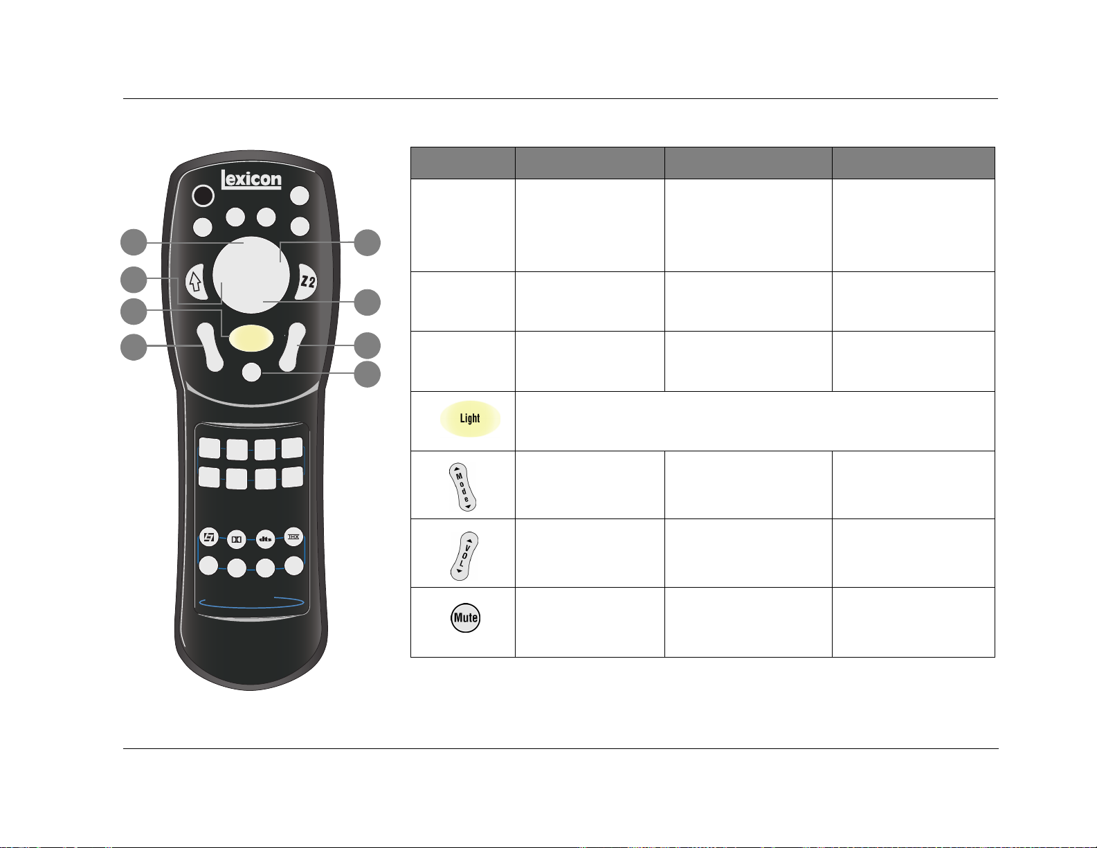
COMMAND MATRIX
The command matrix describes the commands that the remote control buttons perform when
2
1
each command bank is active.
4
3
7
Off
Blue
FP
Shift
OSD
Menu
On
Stat
Zone 2
5
6
8
g
Tuner
o
M
7/5
V
O
L
VCR
Aux
s
e
d
2 CH
M
Light
o
d
e
Mute
DVD1
DVD2 Sat
TV
CD
L
i
s
t
e
n
i
n
Music
TV
MC-8 Digital Controller
Button Main Zone Zone 2 Shift
1
2
3
4
5
6
7
Deactivates standby mode and
activates the MC-8.
Activates standby mode and
deactivates the MC-8.
Toggles the FRONT PANEL
DISPLAY menu STATUS
parameter between ALWAYS OFF
and its current setting.
Tog g les t h e ON- S CREE N
DISPLAY menu BACKGROUND
parameter between ON and
OFF.
Tog g les t h e ON- S CREE N
DISPLAY menu STATUS
parameter between ON and
OFF.
Displays the Main Zone two-line
status for 2 seconds.
Activates an additional bank of commands that control the Main Zone. Refer to the previous page for
more information.
Reserved for future possibilities. Reserved for future possibilities.
Deactivates Zone 2. Deactivates the Main Zone.
Centers the AUDIO CONTROLS
menu ZONE2 BALANCE
parameter.
Sets the AUDIO CONTROLS
menu BASS, TREBLE and TILT EQ
parameters to +0.0dB.
Reserved for future possibilities. Activate s th e tr i g g e r o u t p u t
Displays the Zone 2 two-line
status for 2 seconds.
Centers the AUDIO CONTROLS
menu Main Zone BALANCE and
FADER parameters.
Deactivates the trigger output
connector labeled 1 when the
connector is configured for
remote operation.
connector labeled 1 when the
connector is configured for
remote operation.
Toggles between opening and
closing the STATUS menu for the
current input source.
2-14
8
Activates an additional bank of commands that control Zone 2. Refer to the previous page for more
information.
MC-8 Basic Operation
Button Main Zone Zone 2 Shift
10
12
13
Off
Blue
FP
9
Shift
Menu
M
Light
o
d
e
Mute
OSD
On
Stat
Zone 2
11
9
V
O
L
14
9
10
11
15
12
DVD1
TV
DVD2 Sat
CD
L
i
s
t
e
n
VCR
Aux
Tuner
s
e
d
o
M
i
n
g
13
14
Music
TV
2 CH
7/5
Scroll upward ( ) and
downward () through
menu items.
Closes the current menu. Adjusts the AUDIO CONTROLS
Opens the menu structure
and selects the highlighted
menu item.
Activates the remote control backlight, making remote control buttons more visible in the dark.
Scroll to the previous ()
and the next () available
Main Zone listening mode.
Increases () and decreases
( ) Main Zone volume
level in 1dB increments.
Increase () and decrease ()
the output level of the Main
Zone audio output connector
labeled Subwoofer as applied to
the activated listening mode.
menu ZONE2 BALANCE
parameter left.
Adjusts the AUDIO CONTROLS
menu ZONE2 BALANCE
parameter right.
Sets Zone 2 volume level to
–15dB () or –30dB ().
Increases () and decreases
() Zone 2 volume level in 1dB
increments.
Adjust the AUDIO CONTROLS
menu Main Zone FADER
parameter forward ( ) and
backward ().
Adjusts the AUDIO CONTROLS
menu Main Zone BALANCE
parameter left.
Adjusts the AUDIO CONTROLS
menu Main Zone BALANCE
parameter right.
Sets Main Zone volume level
to –15dB () or –30dB ().
Increases () and decreases
() Main Zone volume level in
3dB increments.
MC-8 Digital Controller
15
Toggles between lowering
Main Zone volume level
and restoring Main Zone
volume to its original level.
Toggles between fully muting
Zone2 volume level and
restoring Zone 2 volume to its
original level.
Toggles between fully muting
Main Zone volume level and
restoring Main Zone volume to
its original level.
2-15
Basic Operation Lexicon
Button Main Zone Zone 2 Shift
Off
Blue
FP
Shift
OSD
Menu
M
Light
o
d
e
Mute
DVD1
DVD2 Sat
TV
CD
Tuner
L
i
s
t
e
n
M
i
n
g
Music
TV
MC-8 Digital Controller
On
Stat
Zone 2
16
Selects the DVD1 input for the
Main Zone.
Selects the DVD2 input for the
Main Zone.
Selects the DVD1 input for
Zone 2.
Selects the DVD2 input for
Zone 2.
Increases the AUDIO
CONTROLS menu BASS
parameter in 0.5dB increments.
Increases the AUDIO
CONTROLS menu TREBLE
parameter in 0.5dB increments.
V
O
L
Selects the SAT input for the
Main Zone.
Selects the VCR input for the
Main Zone.
Selects the SAT input for
Zone 2.
Selects the VCR input for
Zone 2.
Increases the AUDIO
CONTROLS menu TILT EQ
parameter in 0.2dB increments.
Sets the AUDIO CONTROLS
menu LOUDNESS parameter to
ON.
VCR
16
Aux
s
e
d
o
Selects the TV input for the
Main Zone.
Selects the CD input for the
Main Zone.
Selects the TV input for Zone 2. De c r ea s es the A UD I O
CONTROLS menu BASS
parameter in 0.5dB increments.
Selects the CD input for Zone 2. D ec r ea s e s th e AU D IO
CONTROLS menu TREBLE
parameter in 0.5dB increments.
2 CH
7/5
Tuner
Selects the TUNER input for the
Main Zone.
Selects the TUNER input for
Zone 2.
Decreases the AUDIO
CONTROLS menu TILT EQ
parameter in 0.2dB increments.
2-16
Selects the AUX input for the
Main Zone.
Selects the AUX input for
Zone 2.
Sets the AUDIO CONTROLS
menu LOUDNESS parameter to
OFF.
MC-8 Basic Operation
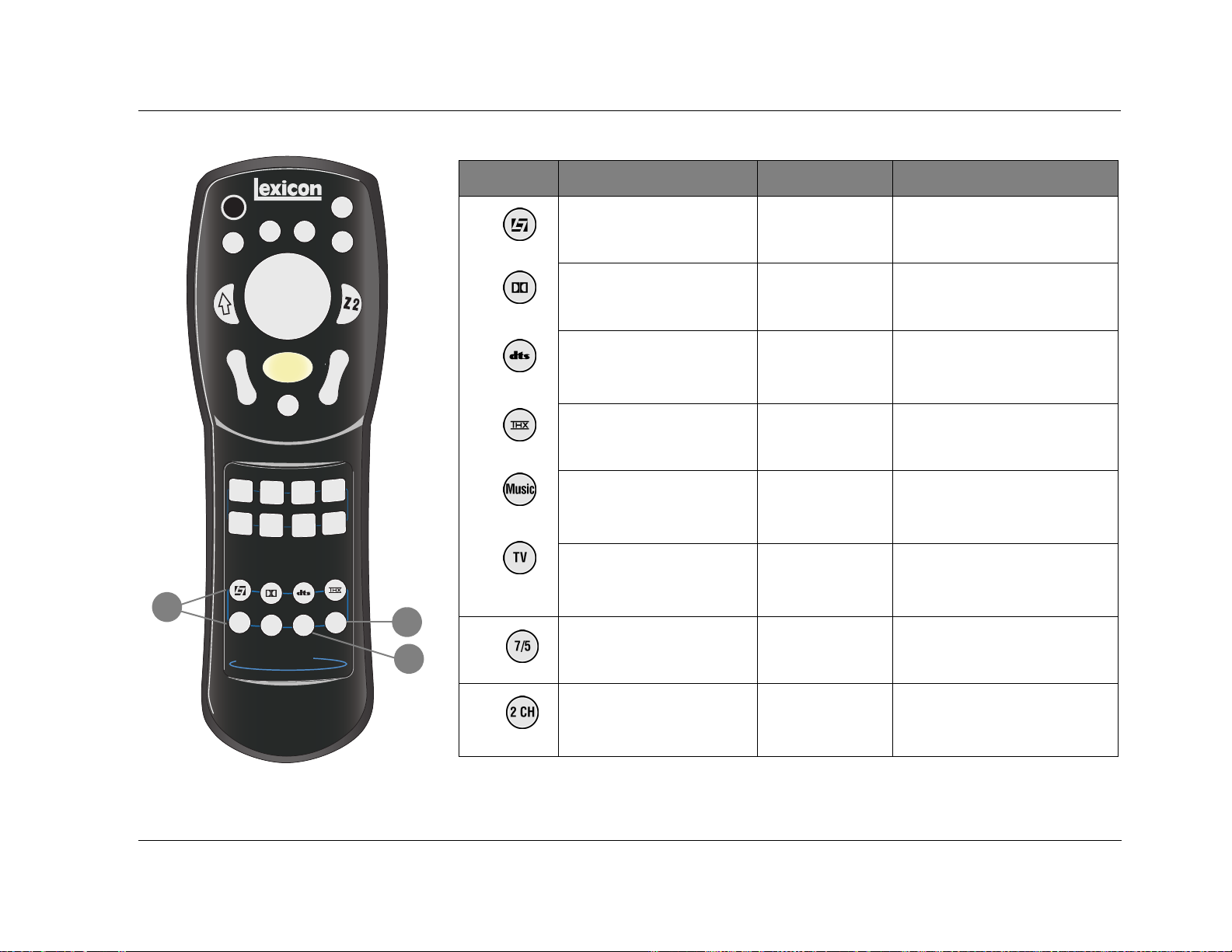
Button Main Zone Zone 2 Shift
17
Off
Blue
FP
Shift
OSD
Menu
M
Light
o
d
e
Mute
DVD1
DVD2 Sat
TV
CD
Tuner
L
i
s
t
e
n
M
i
n
g
Music
TV
MC-8 Digital Controller
On
Stat
Zone 2
17
Selects the LOGIC 7 Film mode
family for the current input
source.
Selects the Dolby mode family for
the current input source.
Selects the DTS(-ES) Cin mode
V
O
L
family for the current input
source.
Selects the THX mode family for
the current input source.
VCR
Aux
Selects the LOGIC 7 Music mode
family for the current input
source.
Selects the LOGIC 7 TV mode
s
e
d
o
family for the current input
source.
Reserved for future
possibilities.
Reserved for future
possibilities.
Reserved for future
possibilities.
Reserved for future
possibilities.
Reserved for future
possibilities.
Reserved for future
possibilities.
Selects the PANORAMA listening
mode.
Refer to the next page.
Refer to the next page.
Refer to the next page.
Selects the L7 MUSIC SURR listening
mode.
Selects the MONO LOGIC listening
mode for 2-channel input sources and
the 5.1 MONO LOGIC listening mode
for 5.1-channel input sources.
2 CH
7/5
19
18
18
Toggles between 7 and 5-channel
playback.
Reserved for future
possibilities.
Adjusts the MAIN ADV menu INPUT
SELECT parameter, cycling through the
ANALOG, DIGITAL and AUTO settings.
19
Toggles between the current
listening mode and the 2CHANNEL listening mode.
Reserved for future
possibilities.
Toggles the MAIN ADV menu 2-CH
ANLG BYP parameter between ON and
OFF.
2-17

Basic Operation Lexicon
Shift-DOLBY
When the Shift command bank is activated, pressing the remote
control DOLBY button while a 5.1-channel Dolby Digital input
source is present activates the DOLBY DIGITAL EX or DOLBY
DIGITAL listening mode. Subsequent presses toggle the EX
DECODING parameter, cycling through the AUTO, ON and OFF
settings.
Shift-DTS
When the Shift command bank is activated, pressing the remote
control DTS button while a DTS(-ES) input source is present toggles
the ES DECODING parameter, cycling through the AUTO, ON and
OFF settings.
Shift-THX
When the Shift command bank is activated, pressing the remote
control THX button while a 5.1-channel Dolby Digital input source
is present activates the THX UL2Cin or THX SurEX listening mode.
Subsequent presses toggle the SURROUND EX parameter, cycling
through the AUTO, ON and OFF settings.
UNDERSTANDING THE ZONES
The MC-8 features two zones of operation, called the Main Zone
and Zone 2. The Main Zone controls audio and video sources in the
primary listening space. Zone 2 controls audio and video sources in
the secondary listening space.
These zones have separate digital audio receivers and dedicated
analog source selectors that allow for independent input selection
in each zone. For instance, the MC-8 can play a DVD in the Main
Zone and a CD in Zone 2 at the same time.
The following are exceptions to independent zone operation:
1. When a Dolby Digital or DTS-ES source is present in the Main
Zone, the same Dolby Digital or DTS-ES source can also be
present in Zone 2. However, different Dolby Digital or DTS-ES
sources cannot be present in both zones at the same time.
2. Main Zone multichannel audio can be down-mixed in Zone 2
when all of the following conditions are met:
• A Dolby Digital or DTS-ES source is present in the Main Zone.
• The Main Zone input is also selected in Zone 2.
• The INPUT SETUP menu ZONE2 IN parameter is set to
DMIX.
3. When the INPUT SETUP menu ZONE2 IN parameter is set to
ANLG, the Zone 2 audio output connectors carry the FRONT L/R
speaker audio from the Main Zone. However, it is possible to
have a 5.1-channel analog audio source present in the Main
Zone and a digital input source present in Zone 2.
2-18
 Loading...