


CP-1 Digital Audio Environment
Processor
Owner's
Manual
CP-1 Plus (Version 2.0)
Lexicon
Unpacking and Inspection
After unpacking the CP-1, save all packing materials in case you ever need to ship the unit. Thoroughly inspect the CP-1 and packing materials for signs of damage. Report any shipment damage to the carrier at once; report equipment malfunction to your dealer.
Precautions
This equipment has been tested and found to comply with the limits for a Class B digital device, pursuant to Part 15 of the FCC Rules. These limits are designed to provide reasonable protection against harmful interference in a residential installation. This equipment generates, uses and can radiate radio frequency energy and, if not installed and used in accordance with the instructions, may cause harmful interference to radio communications. However, there is no guarantee that interference will not occur in a particular installation. If this equipment does cause interference to radio or television reception, which can be determined by turning the equipment off and on, the user is encouraged to try to correct the interference by one or more of the following measures:
Reorient or relocate the receiving antenna.
Increase the separation between the equipment and the receiver.
Connect the equipment into an outlet on a circuit different from that to which the receiver is connected.
Consult the dealer or an experienced radio/TV technician for help.
This triangle, which appears on your component, alerts you to the presence of uninsulated, dangerous voltage inside the enclosure... voltage that may be sufficient to constitute a risk of shock.
CAUTION
RISK OF ELECTRIC SHOCK
DO NOT OPEN
This triangle, which appears on your component, alerts you to important operating and maintenance instructions in this accompanying literature.
WARNING:
TO REDUCE THE RISK OF FIRE OR ELECTRIC SHOCK, DO NOT EXPOSE THE UNIT TO RAIN OR MOISTURE.
Acknowledgements
WARNING:
DO NOT DEFEAT OR REMOVE GROUND PIN ON THE POWER PLUG.
The CP-1 is manufactured under license from Dolby Laboratories Licensing Corporation. Additionally licensed under one or more of the following patents: U.S. numbers 3,632,886, 3,746,792 and 3,959,590; Canadian numbers 1,004,603 and 1,037,877. "Dolby" and the double- D symbol are trademarks of Dolby Laboratories Licensing Corporation.
"Auto-Azimuth" and the A-Z logo
AUTO AZIMUTH
are trademarks of Lexicon, Inc.
Copyright ©1992 Lexicon. Inc.
All Rights Reserved.
Lexicon Patent: U.S. no. 4, 862, 502; other patents pending.
Lexicon, Inc.• 3 Oak Park • Bedford MA • 01730 USA•Tel: 781-280-0300 • Fax: 781-280-0490
Lexicon Part #070-09113 |
Printed in the United States of America |
|
Safety Suggestions
Read Instructions Read all safety and operating instructions before operating the unit.
Retain Instructions Keep the safety and operating instructions for future reference.
Heed Warnings Adhere to all warnings on the unit and in the operating instructions.
Follow Instructions Follow operating and use instructions.
Heat Keep the unit away from heat sources such as radiators, heat registers, stoves, etc., including amplifiers which produce heat.
Ventilation Make sure that the location or position of the unit does not interfere with its proper ventilation. For example, the unit should not be situated on a bed, sofa, rug, or similar surface that may block the ventilation openings; or, placed in a cabinet which impedes the flow of air through the ventilation openings.
Wall or Ceiling Mounting Do not mount the unit to a wall or ceiling except as recommended by the manufacturer.
Power Sources Connect the unit only to a power supply of the type described in the operating instructions, or as marked on the unit.
Grounding or Polarization* Take precautions not to defeat the grounding or polarization of the unit’s power cord.
*Not applicable in Canada.
Power Cord Protection Route power supply cords so that they are not likely to be walked on or pinched by items placed on or against them, paying particular attention to cords at plugs, convenience receptacles, and the point at which they exit from the unit.
Nonuse Periods Unplug the power cord of the unit from the outlet when the unit is to be left unused for a long period of time.
Water and Moisture Do not use the unit near water — for example, near a sink, in a wet basement, near a swimming pool, near an open window, etc.
Object and liquid entry Do not allow objects to fall or liquids to be spilled into the enclosure through openings.
Cleaning The unit should be cleaned only as recommended by the manufacturer.
Servicing Do not attempt any service beyond that described in the operating instructions. Refer all other service needs to qualified service personnel.
qualified service personnel when:
the power supply cord or the plug has been damaged,
objects have fallen, or liquid has been spilled into the unit,
the unit has been exposed to rain,
the unit does not appear to operate normally or exhibits a marked change in performance,
the unit has been dropped, or the enclosure damaged.
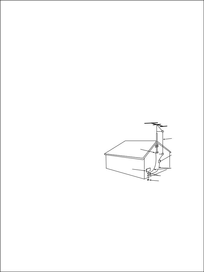
Outdoor Antenna Grounding If an outside antenna is connected to the receiver, be sure the antenna system is grounded so as to provide some protection against voltage surges and built-up static charges. Section 810 of the National Electrical Code, ANSI/NFPA No. 70-1984, provides information with respect to proper grounding of the mast and supporting structure, grounding of the lead-in wire to an antenna-discharge unit, size of grounding conductors, location of antenna-discharge unit, connection to grounding electrodes, and requirements for the grounding electrode. See figure below.
Power Lines An outside antenna should be located away
|
Antenna Lead-in |
|
|
Wire |
|
Ground |
|
|
Clamp |
|
|
|
Antenna Discharge |
|
|
Unit (NEC Section |
|
Electric |
810-20) |
|
Service |
Grounding Conductors |
|
Equipment |
||
(NEC Section 810-21) |
||
|
||
|
Ground Clamps |
|
|
Power Service Grounding |
|
|
Electrode System |
|
NEC — National Electrical Code |
(NEC Art 250, Part H) |
|
|
from power lines.
Damage requiring service The unit should be serviced by

CP-1 Digital Audio Environment Processor
Table of Contents
1 |
Controls and Indicators |
|
|
Introduction |
1 |
|
System Overview |
3 |
|
The Front Panel |
4 |
|
The Rear Panel |
5 |
|
The Remote Control |
6 |
2 |
Connection and Calibration |
|
|
Installation |
7 |
|
Connections to Other Equipment |
9 |
|
Setting the Main Input |
|
|
and Output Levels |
11 |
|
Calibrating the Listener Position |
13 |
3 |
Speaker Set-Up and Configuration |
15 |
4 |
Using The Programs |
|
|
To Load, Modify |
|
|
and Store Programs |
21 |
|
The Modes: |
|
|
Panorama |
22 |
|
Concert Halls |
24 |
|
Music Surround |
28 |
|
Movie Surround |
32 |
|
To Rename and Store a Register |
36 |
5 |
Troubleshooting |
37 |
6 |
Theory and Design |
41 |
7 |
Specifications |
63 |
CP-1
Digital Audio
Environment
Processor
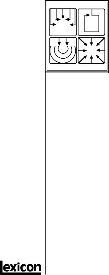
Panorama |
Ambience |
Reverb |
Surround |
Owner's
Manual
CP-1 Plus (Version 2.0)

Controls
Indicatorsand 1
CP-1 Digital Audio Environment Processor
Introduction
All of the operating modes in the Lexicon CP-1 Digital Audio Environment Processor have a common goal: to draw you, the listener, more deeply into a musical performance or a film. For music the CP-1 uses unique digital processing to re-create either the original recording space or a new one of your choosing. For films it offers an extremely accurate version of Dolby Pro Logic Surround decoding and our own decoding for monaural film soundtracks. The increase in impact of a musical performance or film when heard with the CP-1 is enormous, especially when widely spaced multiple loudspeakers are provided, but even without additional loudspeakers, significant gains are made.
To re-create the experience of being at a performance the CP-1 draws on recent studies of concert-hall acoustics, and applies this research to home listening rooms. Our auditory sense is quite adept at interpreting clues about our physical environment. Even with your eyes closed, it is possible to get a good mental picture of the room or hall you are in by listening to the ambience, or reflected sound energy, in the room. We are not aware of our auditory sense in everyday life because it confirms what our eyes identify as the environment. When we listen to recorded music, however, there are no visual clues and we rely completely on our sense of hearing. The introduction of two-speaker stereo systems over thirty years ago brought dramatic improvement to high fidelity music reproduction. With a care- fully-designed system, and good recording, it became possible to produce a good sonic picture of the original event. Unfortunately, our listening rooms do not approximate the acoustics of a good concert hall, an intimate jazz club, or a magnificent cathedral — our ears tell us where we really are. The Lexicon CP-1 is designed to overcome this fundamental limitation to two-speaker reproduction and bring us closer to the ultimate goal of transporting ourselves to the original musical event.
The object is to increase the sideways-moving sound in a room, thus increasing Spatial Impression, or SI. The CP-1 increases SI by either extracting it from the original recording, using the Panorama or Surround effects, or by generating a new acoustic environment with the Ambience or Reverb effects.
When a listener is in the correct spot the Panorama mode provides an almost ideal re-creation of the original recording space. It works by using digital processing to cancel the crosstalk between the listener's ears, effectively spreading the sound from the two front loudspeakers in a wide arc in front of the listener. With the optional addition of rear speakers, Panorama can be almost spooky in its realism.
The Ambience and Reverberation effects in the Concert Hall modes transform the listening room into a new acoustic space, letting you choose an environment which matches your music or your mood. Unlike most ambience processors, the CP-1 provides full stereo processing, preserving the critical SI information in the recording and expanding upon it.
Page 1

Lexicon
The Ambience effect generates the side and rear reflection patterns of an idealized club and concert hall. The larger space adds the true depth and realism of a concert hall to classical and popular music, while the smaller space is ideal for jazz and rock. The Reverberation effect is similar, but places more emphasis on rich, dense reverberant decay than on early reflections. It is especially good for simulating large, highly reverberant spaces such as churches, stadiums and cathedrals.
For films encoded with Dolby Stereo, the CP-1 uses a completely digital Dolby Pro Logic Surround decoder, with automatic correction of azimuth and channel-balance errors (the most common problems in currently available films). The CP-1 also provides modes for expanding monaural film sound tracks (Mono Logic), general TV viewing (TV Matrix) and for playing music through a Surround speaker set-up (Music Surround).
Page 2

CP-1 Digital Audio Environment Processor
Although the CP-1 performs very complex signal processing, a great deal of |
System Overview |
|
effort has gone into making the technology behind the effects as transparent |
|
|
as possible to the user. To understand the overall organization of the unit, |
|
|
it is helpful to define those few terms which are unique to the CP-1. |
|
|
|
Glossary of Terms |
|
Mode A mode is a configuration that determines how the CP-1 will |
||
|
||
process an input signal. The CP-1 contains four basic modes: Panorama, |
|
|
Concert Halls, Music Surround and Movie Surround. Each of these |
|
|
basic modes has a set of variations which are labeled on the remote (1- |
|
|
12). In this manual, these 12 variations are also referred to as modes. |
|
|
Effect In the CP-1, an effect is the algorithm which defines a particular |
|
|
mode. The four effects in the CP-1 are: Panorama, Ambience, Reverb |
|
|
and Surround. |
|
|
Parameter Each mode has a set of parameters (controls) that uniquely |
|
|
characterize it. The settings of the parameters can be changed to create |
|
|
custom User modes. |
|
|
Mode Parameter values are stored/recalled in Presets and User modes. |
|
|
Some examples are: Delay Time, Bass Split, etc. |
|
|
System parameter values are not associated with a particular mode. |
|
|
System parameters are not stored in User registers or Presets, nor do |
|
|
their values change when a new mode is recalled. Examples are: display |
|
|
contrast, volume, etc. |
|
|
Register The CP-1 contains 24 registers, or memory locations, where |
|
|
modes are stored. |
|
|
Bank The CP-1's 24 registers are organized into 2 banks, of 12 each. |
|
|
Presets One bank of 12 registers is loaded with the modes which appear |
|
|
on the remote. These modes are presets which are permanently initial- |
|
|
ized at the factory. The factory presets cannot be overwritten, but they |
|
|
can be modified and stored into User registers (or copied into |
|
|
registers,then modified). |
|
|
User Registers The remaining 12 registers are designated as User registers. |
|
|
These are available for storing your own custom modes. When shipped, |
|
|
the CP-1 has a duplicate of the presets loaded into the User bank. These |
|
|
will be overwritten when you modify them. |
|
|
|
|
Page 3
Controls and
Indicators
The Front Panel
Lexicon
|
exicon |
DIGITAL AUDIO ENVIRONMENT PROCESSOR |
|
|
|
|
|
|
|
|
|
|
|
|
|
|
|
|
|
|
|
|
|
|
|
|
|
CP-1 |
|||||||||
|
|
|
|
|
|
|
|
|
|
|
|
|
|
|
|
|
|
|
|
|
|
|
|
|
|
|
|
||||||||||
|
|
|
|
|
|
|
|
|
|
|
|
|
|
|
|
|
|
|
|
|
|
|
|
|
|
|
|
|
|
|
|
|
|
|
|
|
|
|
|
|
|
|
|
|
|
|
|
|
|
|
|
|
|
|
|
|
|
|
|
|
|
|
|
|
|
|
|
|
|
|
|
|
|
|
|
|
|
|
|
|
|
|
|
|
|
|
|
|
|
|
|
|
|
|
|
|
|
|
|
|
|
|
|
|
|
|
|
|
|
|
|
|
|
|
|
|
|
|
|
|
|
|
|
|
|
|
|
|
|
|
|
|
|
|
|
|
|
|
|
|
|
|
|
|
|
|
|
|
|
|
|
|
|
|
|
|
|
|
|
|
|
|
|
|
|
|
|
|
|
|
|
|
|
|
|
|
|
|
|
|
|
|
|
|
|
|
|
|
|
|
|
|
|
|
|
|
|
|
|
|
|
|
|
|
|
|
|
|
|
|
|
|
|
|
|
|
|
|
|
|
|
|
|
|
|
|
|
|
I |
|
II |
SOURCE TAPE |
PRE |
|
POST |
|
|
|
|
|
|
|
|
|
|
|
|
|
|
|
|
|
|
|
SYSTEM |
EFFECT |
POWER |
||||||||
|
|
|
|
|
|
|
|
|
|
|
|
|
|
|
|
|
|
|
|
|
|
|
|
|
|
|
|
|
MUTE |
MUTE |
|
|
|
||||
|
|
|
|
|
|
|
|
|
|
|
|
|
|
|
|
|
|
INPUT LEVEL |
|
|
|
|
|
|
|
||||||||||||
|
|
SOURCE |
MONITOR |
|
TAPE |
|
|
|
|
|
|
|
|
|
|
|
|
|
|
|
|
|
|
|
|
DOLBY SURROUND |
|
|
|
||||||||
|
|
|
|
|
|
|
|
|
|
|
|
|
|
|
|
|
|
|
|
|
|
|
P R O |
|
L O G I C |
|
|
|
|||||||||
|
|
|
|
|
|
|
|
|
|
|
|
|
|
|
|
|
|
|
|
|
|
|
|
|
|
|
|
|
|
|
|
|
|
||||
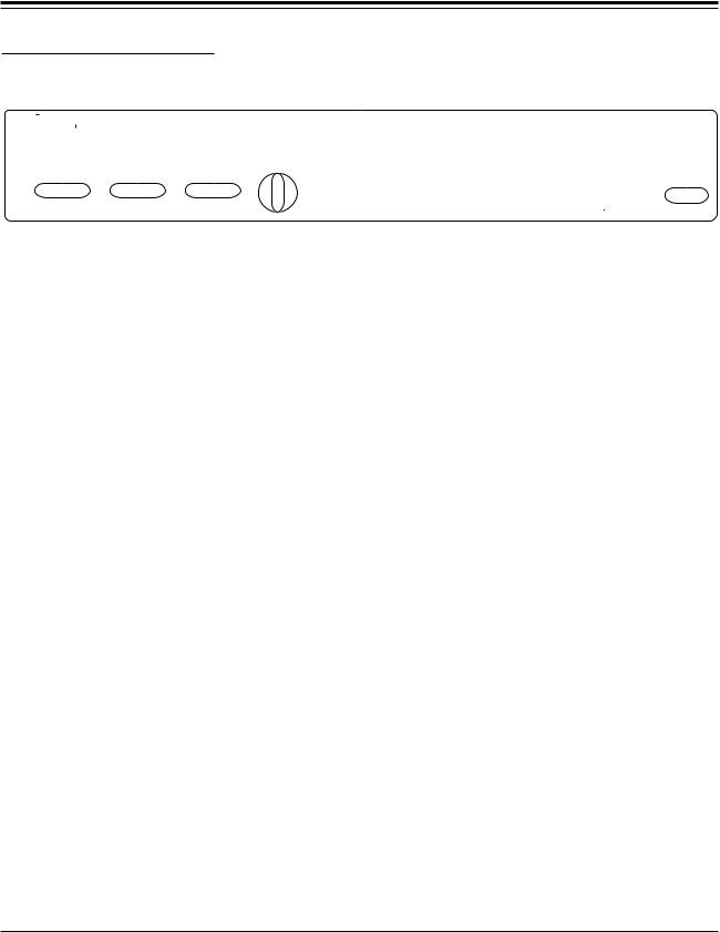
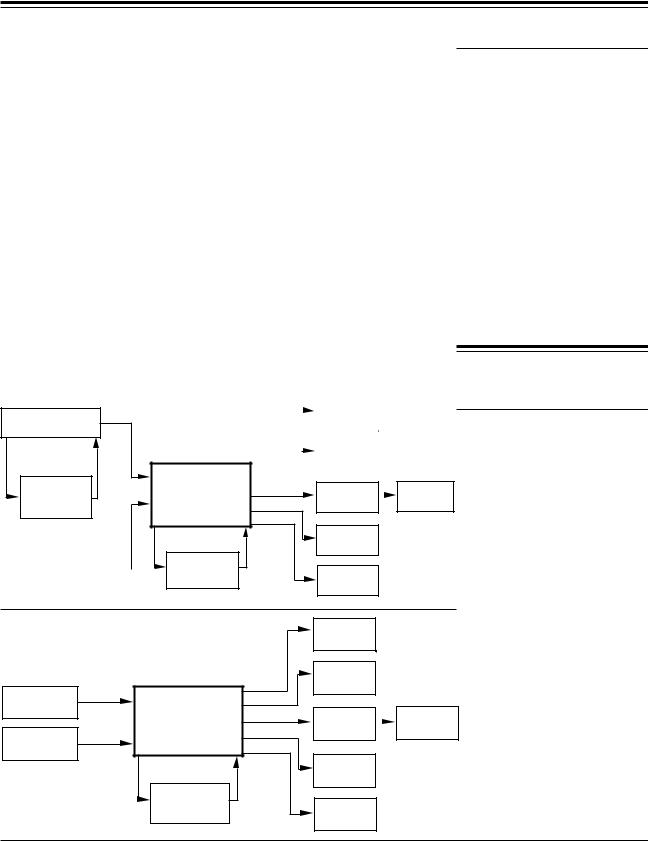
Source The SOURCE buttons select one of two identical stereo pairs of audio inputs. Ordinarily Input I will be connected to the main outputs of your stereo preamp and the second input will be a spare. In video installations, Input I will be connected to the main audio outputs of your TV receiver, VCR or audio/video control center. Input II can then accept the outputs of a separate system or the audio outputs of a video disc or CD player.
Monitor The MONITOR button selects SOURCE I/II or TAPE IN. The Tape inputs are provided to accommodate a recorder if the CP-1 occupies a previously used tape monitor loop.
Tape The PRE and POST Tape switch determines whether CP-1 processing if applied before or after tape output. PRE means that the tape deck gets the signal unaltered (PRE-processing); POST applies CP-1 processing to the tape output (POST-processing).To record CP-1 processing onto tape the CP-1 must be in the two-speaker mode (Configuration 1) with the POST button engaged.
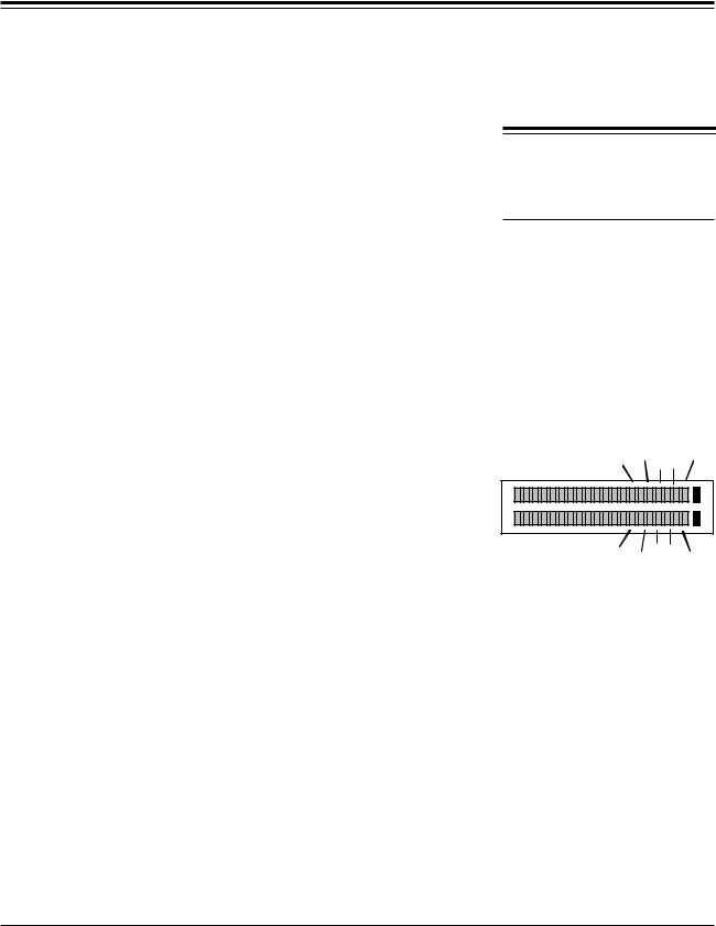
Input Level The INPUT LEVEL control and its display allow you to match the level of the incoming signal to the CP-1’s digital encoding circuits. When correctly set, loud passages will light the entire row of green LEDs without flashing the red ones.
Alphanumeric The alphanumeric display shows both the effect that is running and its
Display modifiable parameters. The CP-1 has 24 registers: PRESETs 1-12 are configured at the factory; those labeled USER 1-12 are available for storage
of programs customized by the user.
Indicator The unlabeled LED to the left of the System Mute Indicator lights when the
Lights CP-1 detects a signal from the remote control. The SYSTEM MUTE LED indicates that unprocessed audio is no longer passing through to the CP-1's
main outputs. The EFFECT MUTE LED indicates that the CP-1’s processed audio is no longer passing through to its outputs.
Power System On/Off.
Page 4

Controls and
Indicators
CP-1 Digital Audio Environment Processor
The Rear Panel
|
LEVEL |
|
|
REAR SIDE |
MAIN |
TAPE |
INPUTS |
|
|
OUT |
|
L
OUTPUTS
R
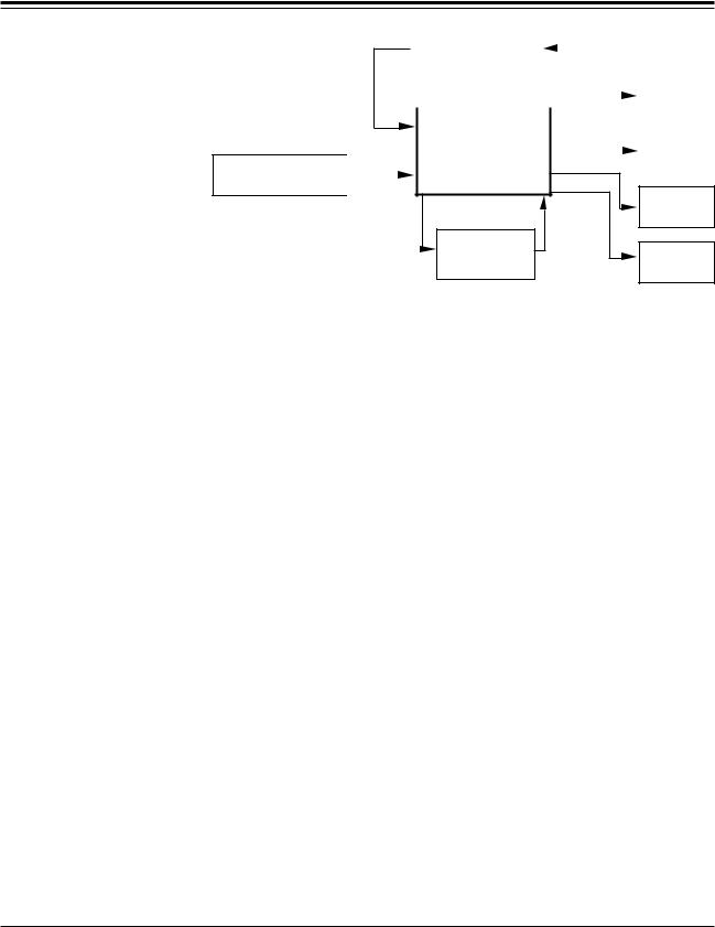
Stereo outputs for rear and side power amplifiers, with level adjusting knobs. The procedure for balancing these outputs (as well as the center channel and subwoofer) with the main pair begins on page 11.
Main outputs, with level adjustment. Level-setting of these outputs must precede adjustment of the auxiliary channels.
The adjustment of the subwoofer output should be done only after all other channels are calibrated. (See pages 12 and 19.)
Center channel output with level control and button. Push the button in if you have no center channel; leave it out if a center speaker is connected. NOTE: Leaving this button out with no center channel will cause the Surround modes to malfunction.
Inputs and outputs for an additional audio or video tape deck (audio portion only) or to replace the monitor loop occupied by the CP-1.
Rear and Side
Outputs
Main, Center
and Subwoofer
Outputs
Center/Out
Phantom/In
Tape Out/In
Two sets of main inputs, selected by the SOURCE I/II buttons. |
Inputs |
Page 5
Controls and
Indicators
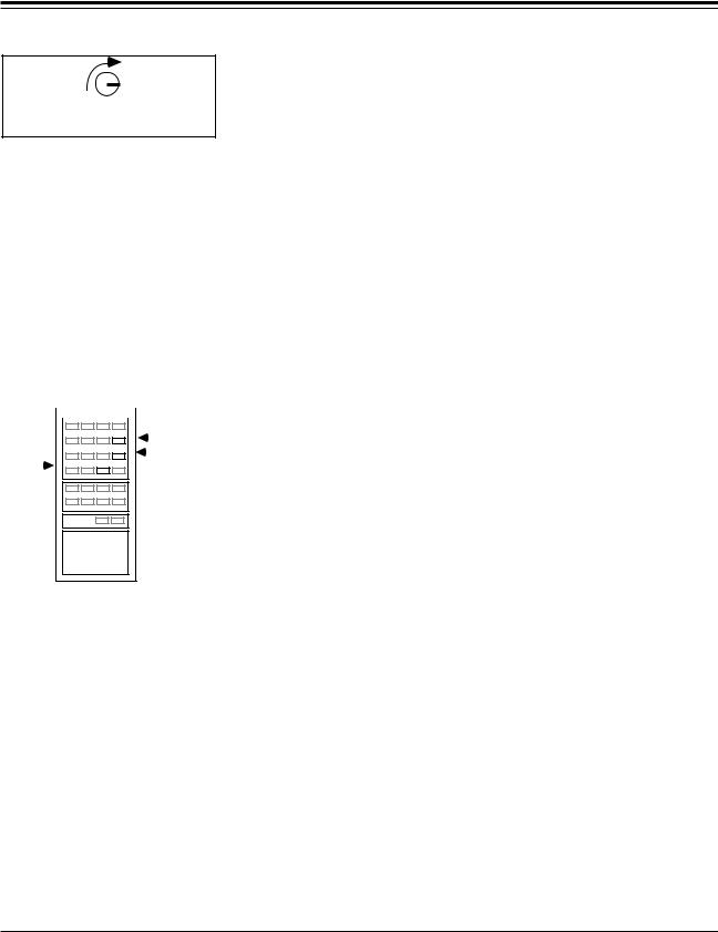
The Remote Control
Lexicon
PANORAMA |
BANK |
|||
1 |
2 |
3 |
|
|
NORMAL |
WIDE |
BINAURAL |
|
|
CONCERT HALLS |
PARAM |
|||
4 |
5 |
6 |
||
CLUB |
HALL |
CATHEDRAL |
|
|
MUSIC SURROUND |
|
|||
7 |
8 |
9 |
||
FULL |
MUSIC |
STEREO |
|
|
MOVIE SURROUND |
|
|||
10 |
11 |
12 |
|
|
MONO TV MATRIX |
|
|
||
|
F |
R |
|
|
EFFECT |
BALANCE |
VOLUME |
||
|
B |
L |
|
|
DOLBY SURROUND |
SYSTEM |
EFFECT |
||
MUTE |
||||
DOLBY SURROUND |
||||
P R OPRO L- LOGICC |
|
|
||
The Modes
Panorama
The PANORAMA modes provide enhanced lateral sound (and hence greater spaciousness and envelopment) for either music or films. PANORAMA can utilize left and right rear channels but is also effective using only the two front loudspeakers. NORMAL(1) and WIDE(2) differ primarily in their initial Effect Levels. BINAURAL(3) is for playback on loudspeakers of recordings made with a dummy head.
Ambience Reverb
The CONCERT HALL modes simulate halls of three different sizes, generating reflections of appropriate directionality, delay and spectral shape and sending them to the side and rear speakers. The Ambience effect in the Small Club (4) and Concert Hall (5) modes provides adjustable recirculation through the Liveness parameter. The Reverb effect in the Cathedral mode (6) has fewer specific initial reflections than the smaller spaces but richer and smoother reverberant decay. Cathedral is especially good for simulating large, highly reverberant spaces.
Page 6

Controls and
Indicators
CP-1 Digital Audio Environment Processor
The MUSIC SURROUND modes allow you to play music through a system of surround speakers. FULL RANGE (7) allows unprocessed music to be played over all the speakers for background music, or for maximum acoustical output of the system. MUSIC LOGIC (8) enhances music through a unique ambience extraction method, and can provide spectacular results with music that has carefully recorded stereo information. STEREO LOGIC
(9) enhances music with surround speakers and also allows the listener to adjust certain parameters for film sound.
The MOVIE SURROUND modes work with film sound tracks to recreate the theater experience. MONOLOGIC (10) expands the music and effects on monaural films into the additional channels while leaving the dialog in the front center. TV MATRIX (11) is designed to expand and enhance a wide range of television programming. This mode also allows adjustment of certain parameters for film sound which are not adjustable in mode 12. Dolby PRO LOGIC (12) provides the same decoding used in Dolby Stereo theater systems, using up to eight speakers for front, center, side, rear and subwoofer channels.
The BANK button switches between the 12 factory-presets and 12 user registers where customized programs may be stored. The number doesn't change: if you are using Preset 9, BANK switches to User 9 and vice-versa. Holding BANK for a few seconds puts the CP-1 into Configuration mode, in which the three Parameter buttons adjust the LCD contrast and select one of the 12 speaker setups illustrated on page 15.
Surround
Bank
The three PARAMETER buttons allow selection and adjustment of variable |
Parameter |
parameters within each mode. Pushing PARAM displays the current pa- |
|
rameter for five seconds; pushing it again before the display changes selects |
|
the next parameter. Pressing PARAM UP or DOWN will display and adjust |
|
the current parameter, whether or not PARAM has been pushed. A single |
|
push changes the parameter by one unit; holding the button for more than |
|
one second causes the values to change rapidly in an auto-repeat mode. |
|
PARAM can also put the CP-1 into TEST mode. (See page 21.) |
|
EFFECT: UP and DOWN adjust the level of all signals added by the CP-1. |
Effect* |
BALANCE: F and B adjust the levels of the rear speakers relative to the |
Balance* |
sides and fronts. |
|
BALANCE: L and R adjust the left/right balance of all speakers: front, sides |
|
and rear. It assumes the function of the balance control on your preamp or |
|
receiver. |
|
VOLUME: UP and DOWN adjust the level of all channels simultaneously. |
Volume* |
*The first push of either of this pair of buttons displays the current value for five seconds; |
|
another push during that time increases or decreases the displayed value. Holding the button |
|
down for 1 second engages auto-repeat, changing the value rapidly. |
|
|
|
Page 7

Controls and
Indicators
Lexicon
Mute SYSTEM MUTE turns off all outputs and lights both SYSTEM and EFFECT MUTE LEDs. Pushing EFFECT MUTE while in systemmute mode turns the effects alone back on.
Pressing SYSTEM MUTE, then EFFECT MUTE, allows you to hear only the effect channels of the CP-1. This is particularly useful for making fine adjustments of parameters.
EFFECT MUTE alternately turns off and on all signals added by the CP-1. Use it to compare the sound with and without CP-1 processing. In TEST mode EFFECT MUTE clears all user memories. (See page 21.)
Page 8
Connection
and 2
Calibration
CP-1 Digital Audio Environment Processor
Installation
The CP-1 may be installed on a shelf or in a standard 19" equipment rack. (Contact Lexicon or your local dealer for hardware sources.) Connect the power cord to a wall outlet or to a switched outlet on the back of your preamplifier. Observe the following precautions:
• Make sure the remote control receiver, located on the right side of the Precautions front panel, is unobstructed. The remote control must be in line of sight
to this receiver for proper operation. The CP-1 may be placed in a glassdoored cabinet but smoked glass will make the display hard to read.
•Select a dry, well-ventilated location out of direct sunlight.
•Do not stack the CP-1 directly above heat-producing equipment such as power amplifiers.
•Avoid placing the CP-1 near unshielded TV or FM antennas. The CP-1 may interfere with some FM tuners if it is placed immediately above or below them.
•Install two AAA batteries in the CP-1’s remote control.
AUDIO |
MAIN |
PREAMP |
OUT |
TAPE |
|
OUT/IN |
|
PROGRAM EQ |
I |
or |
INPUTS |
DYNAMIC RANGE |
II |
PROCESSOR |
|
VCR, TV, VIDEO |
AUDIO |
CONTROL CENTER |
OUT |
|
|
Connections to
Other Equipment
|
|
|
|
CENTER |
|
|
|
|
AMP |
|
|
|
|
|
|
|
|
|
|
|
|
|
|
REAR |
CENTER |
|
|
|
AMPS |
|
|
|
|
|
REAR |
|
|
|
|
|
|
|||
CP-1 |
MAIN |
(SPEAKER |
MAIN |
SIDE |
EQ) |
POWER AMPS |
|
|
|
|
|
|
SUB |
|
|
TAPE |
WOOFER |
SIDE |
|
|
|
||
OUT/IN |
|
AMPS |
|
VCR |
|
|
Connections with an |
or |
|
SUBWOOFER |
|
CASSETTE DECK |
|
||
|
AMP |
Audio Preamp |
|
|
|
||
|
|
|
|
|
|
|
CENTER |
|
|
|
|
|
AMP |
|
|
|
|
|
REAR |
|
|
|
|
CENTER |
AMPS |
|
|
|
|
|
|
|
CD |
MAIN OUT |
|
REAR |
|
|
|
|
|
|
||
|
I |
CP-1 |
MAIN |
(SPEAKER |
MAIN |
|
INPUTS |
||||
|
|
EQ) |
POWER AMPS |
||
|
II |
SIDE |
|||
VIDEO |
|
|
|
||
|
|
|
|
|
|
DISC |
AUDIO OUT |
|
SUB |
|
|
|
|
WOOFER |
|
|
|
|
|
TAPE |
SIDE |
|
|
|
|
|
|
||
|
|
OUT/IN |
|
AMPS |
|
|
|
AUDIO or VIDEO |
|
|
|
|
|
CASSETTE |
|
SUBWOOFER |
|
|
|
RECORDER |
|
|
|
|
|
|
AMP |
|
|
|
|
|
|
|
Using the CP-1 as an
Audio Preamp
Page 9
Connection and
Calibration
Lexicon
Connecting the CP-1
in a Tape Monitor Loop
TAPE
OUT
|
I |
|
INPUTS |
VCR, TV, VIDEO |
II |
AUDIO |
|
CONTROL CENTER |
OUT |
|
|
|
INTEGRATED AMP, |
|
|
TAPE |
|
||||
|
PREAMP or RECEIVER |
|
|
|
IN |
|
|
|
|
|
|
|
|
|
|
|
|
|
|
|
|
|
|
|
|
|
|
|
|
|
|
|
|
|
|
|
|
|
CENTER |
|
|
|
|
|
MAIN |
|
|
|
AMP |
|
|
|
|
|
|
|
|
|
|
|
|
|
|
CENTER |
|
|
|
||
|
|
|
|
|
|
|
|||
|
CP-1 |
|
|
REAR |
|
REAR |
|||
|
|
|
SIDE |
AMPS |
|||||
|
|
|
|
|
|
||||
|
SUB |
|
TAPE |
WOOFER |
SIDE |
|
||
|
AMPS |
|
OUT/IN |
|
|
VCR |
|
|
or |
|
SUBWOOFER |
CASSETTE DECK |
|
|
|
AMP |
|
|
|
Note
Audio Inputs
Note
If you have a receiver with no external access to the preamplifier outputs (or you wish to use the tape monitor loop on your preamp), you can use a tape output or external processor loop to the CP-1. However, any change in the receiver’s volume control after the system is adjusted will upset the balance between the main and auxiliary speakers. If you are using this configuration, you should now turn the receiver’s volume control all the way down. If there was a tape deck previously connected to your receiver's monitor loop, connect it to the CP-1's tape outputs and inputs.
Turn off ALL audio and video components, including individual power amplifiers. (Unplug any preamps and power amps that don’t have switches.) Locate the gain trim potentiometers on the CP-1 rear panel; these are knobs at the top of the panel, marked REAR, SIDE, MAIN, CENTER and SUB. Turn each one all the way down (counterclockwise as viewed from the back).
Connect the main outputs of your audio preamplifier or the preamplifier output of your receiver to Input I on the CP-1.
Inputs I and II are electrically identical and can be used interchangeably. The CP-1 will also act as a line-level preamp with three inputs (including the built-in tape monitor loop) if you wish to connect, for example, the audio outputs from a TV receiver/monitor, a CD player and a VCR directly to it.
Audio Outputs Connect the CP-1’s MAIN outputs to your main stereo channels. Connect any additional amplifier/speaker combinations to the remaining outputs on the CP-1. Refer to page 19 for information regarding subwoofer connection.
Locate the button below the SUB potentiometer marked CENTER/OUT, PHANTOM/IN. If you have no center front speaker, push it in; if you have a center channel, make sure this button is in the out position.
Page 10
CP-1 Digital Audio Environment Processor
Connection
and
Calibration
Push the INPUT I button on the front panel. Push the MONITOR SOURCE and TAPE PRE buttons. Turn the INPUT LEVEL knob all the way down (counterclockwise).
The CP-1 has its own volume and balance controls, which you will be using in place of the ones on your existing preamp or receiver. Set the gains in your main stereo channels for optimum dynamic range as follows.
For best performance, the CP-1 should always be driven to its full Input Level and its system volume set to -05dB for optimum signal levels.
Turn on the CP-1. For the first two seconds the display should read: LEXICON CP-1, with a software version number and a copyright notice. For another two seconds there will be a configuration message, then a program name will appear. When the power-up routine is finished, aim the remote control at the unit and push the EFFECT MUTE button (bottom row, right). The message: EFFECTS OUTPUTS OFF will appear in the display for about 4 seconds and the EFFECT MUTE LED on the front panel will light.
Turn on your preamp, choose a signal source and play some loud music (a heavily compressed FM rock station or heavy-metal CD is ideal). Turn the preamp’s volume control up about three quarters of the way. Adjust the CP- 1’s INPUT LEVEL control until the red level-indicator LEDs at the right of the display blink occasionally, then reduce the INPUT LEVEL until only the green LEDs are lit.
If there are audible differences between the levels of the source you used for this calibration procedure and other sources, you may have to readjust the INPUT LEVEL to accommodate them. Where possible, try to use the output level controls on the various sources to equalize levels.
Push and hold the VOLUME DOWN button on the remote control until the bar graph on the display completely disappears and the display reads SYSTEM VOLUME -64 dB. Turn on the main stereo power amplifier, then hold the VOLUME UP button until the CP-1’s volume is at -05 dB. If the back-panel potentiometers are turned all the way down, as they should be, you will not hear any sound yet. If you hear loud sound as the CP-1’s volume advances, stop and reset all rear-panel gain potentiometers fully counterclockwise until they are completely off before proceeding.
With the CP-1’s remote volume at -05 dB, slowly advance the rearpanel potentiometer for the MAIN OUTPUTS until the sound is as loud as you will normally play the system. Do not touch the gain on your preamp or receiver after this adjustment. Use only the CP-1 volume control. (Make sure that this level is not high enough to cause speaker distortion or amplifier clipping.)
Front Panel
Adjustments
Setting the
Main Input and
Output Levels
Input Levels
Be sure the Input Level is as high as possible without flashing red.
Set all output levels to zero; set Volume UP almost all the way.
Page 11
Connection and
Calibration
Lexicon
Output Levels
Main Output
Set Main Output so system is as loud as you are ever going to need it. (Be careful that this level does not cause speaker distortion or amplifier clipping.)
Balancing
Additional Channels
1. Select |
|
|
|
|
|
|
|
|
|
|
|
2.Push Param to |
||||||
|
|
|
|
|
|
|
|
|
|
|
||||||||
Pro Logic |
|
|
|
|
|
|
|
|
|
|
|
|
|
CALIBRATE |
||||
|
|
|
|
|
|
|
|
|
|
|
|
|
||||||
|
|
|
|
|
|
|
|
|
|
|
||||||||
|
|
|
|
|
|
|
|
|
|
|
|
|
|
|
|
|
|
|
|
|
|
|
|
|
|
|
|
|
|
|
|
|
|
|
|
|
|
|
|
|
|
|
|
|
|
|
|
|
|
|
|
|
|
|
|
|
|
|
|
|
|
|
|
|
|
|
|
|
|
|
|
|
|
|
|
|
|
|
|
|
|
|
|
|
|
|
|
|
|
|
|
|
|
|
|
|
|
|
|
|
|
|
|
|
|
|
|
|
|
|
|
|
|
|
|
|
|
|
|
|
|
|
|
|
|
|
|
|
|
|
|
|
3.Push UP for ON
The output level potentiomenters (the small knobs above the output connectors on the CP-1 rear panel) allow you to balance the sound levels of all the channels in your system relative to each other. The most important thing to keep in mind when calibrating the system is to keep these potentiometers set as low as possible. Your normal listening level (not background muzak level) should be with the system volume (as indicated by the front panel LCD) set to around -10dB. This keeps the processor at its optimum signal levels while allowing headroom if you really want to crank it up.
If you have a sound pressure level meter (SPL meter), set the output level potentiometer so that, with the calibration signal, the meter reads 75dB C- weighted, when the CP-1 system volume is set at -10dB.
If you are using only two audio channels, level adjustment is now complete. If you have additional channels, use the following procedure to set their levels to match the main stereo pair.
Use the VOLUME DOWN button to reduce the CP-1’s level to about -20 dB. If the EFFECT MUTE LED is on, push EFFECT MUTE to cancel it. Push program button 12; the display will read: PRESET 12 on the left and SURROUND PRO LOGIC on the right. Push PARAM six times or until the display reads: CALIBRATE. Push PARAM UP to turn on the calibration signal.
The sound you hear is a band of noise centered around 1 kHz, being sent in sequence to: all channels, left side plus left front, center, right side plus right front and rear channel(s). If you have a center speaker, the rear-panel CENTER/PHANTOM button should be out. Since all levels are down except for MAIN, you will hear only: both fronts, left only, silence, right only, silence. If you have no center speaker, the rear-panel button should be in and you will hear: both fronts, left-only, both fronts,right only, silence.
Now turn on the remaining power amplifiers and turn up SIDE, REAR and CENTER gain until the individual loudness of the sounds reaching your listening position is the same and the all-channel signal is evenly distributed from all speakers. The CALIBRATE ON display will remain for as long as you use this mode. When the front, center, side and rear channels are balanced, press PARAM DOWN to turn off the calibration signal.
Finally, if you are using a separate low-frequency channel, use music or the test signal of your choice to adjust the SUB WOOFER gain until the low bass balances the rest of the spectrum. This completes the initial connections and level adjustments of the CP-1.
Page 12
Connection
and
Calibration
CP-1 Digital Audio Environment Processor
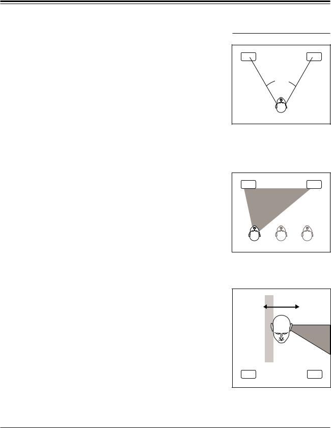
PANORAMA works by canceling the sound going from each speaker to the opposite ear. The strength of the effect is highly dependent on the geometry of your front loudspeakers, the room and your listening position. The correct timing of the canceling signal varies with the angle between your main speakers. The SPEAKER ANGLE parameter, displayed in degrees, adjusts for wide or narrow speaker spacing. For the two canceling signals to arrive at both ears at the same time you must be centered precisely between the speakers. The Listener Position parameter (LISTENER POS) delays the corrections from either channel and allows adjustment for an offcenter listening chair or for asymmetrical speaker placement.
The ideal setup for Panorama is an acoustically dead room, with speakers well away from the walls, and the listener on the center line between the speakers. The effect is diminished by reflections from nearby surfaces. Furthermore, if the listener sees the two speakers from different angles their responses will differ. The addition of acoustic absorption (soft furniture, carpets and drapes) or diffusion (furniture or books that form irregular surfaces and break up reflections) and time spent shifting speakers and chair into more precise alignment (use a tape measure rather than relying on your eyes) will all be rewarded.
Find a mono source, such as an announcer on FM radio or a mono film, and listen for a tightly focused center image of speech or singing. If the image is off-center, adjust the CP-1's BALANCE control. (The narrower the monaural image, the better Panorama will work.) Perform the following setup from a relaxed, comfortable position in your listening chair with your head facing the center point between the speakers.
1.Reduce the volume to about -20 dB. If the display reads: USER at the top left, push Program button 2; if not, push BANK, then button 2 to load PRESET PANORAMA WIDE. Push PARAM eight times (until the display reads: CALIBRATE OFF). Push PARAM UP to turn on the leftchannel calibration signal.
2.The test signal should appear to come from off to your left side, well beyond the left speaker, with near-total silence in the right ear. Still facing forward, move your head from side to side until the effect is strongest. If you can find the sweet spot from the confines of your chair, go directly to step 4; otherwise perform step 3.
3.Push PARAM once so the display reads: LISTENER POS. Push PARAM UP and DOWN until you hear the strongest effect. Then push PARAM four times, or until the display reads: CALIBRATE LEFT ONLY.
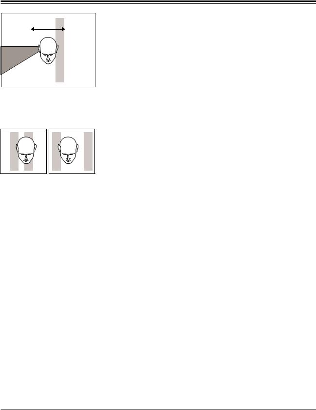
4.Push PARAM UP until the display reads: CALIBRATE RIGHT ONLY. Again, shift your head from side to side to find the sweet spot, this time looking for the point where the silence in the left ear is deepest. Compare the locations of the two sweet spots from steps 2 and 4. If they coincide,
Calibrating the
Listener Position
60° |
SPEAKER ANGLE is the angle between the main speakers as seen from the listening position -here it is about 60° .
L127 . . . Center . . . |
R127 |
LISTENER POS allows you to adjust for an offset listening position.
NOISE |
SILENCE { |
Move your head from side to side to find the position where the noise is full left and the right ear hears near total silence.
Page 13
Connection and
Calibration
Lexicon
NOISE
{SILENCE
When calibrating right, if your left ear is in the silent band, the speaker angle is correct.
If the two silent bands are too close, lower the Speaker Angle; if they are too far apart, raise the Speaker Angle.
go on to step 6; otherwise, perform step 5.
5.Push PARAM twice so the display reads: SPEAKER ANGLE. If the sweet spot from step 2 (LEFT ONLY) is to the left of the sweet spot from step 4 (Right ONLY), push PARAM UP once. If the the step 2 sweet spot is to the right of the step 4 sweet spot, push PARAM DOWN. Push PARAM to return to CALIBRATE RIGHT ONLY and go back to step 2.
6.Adjust your chair so the single sweet spot is in the center, or use PARAM to get to LISTENER POS and adjust this parameter to move the sweet spot to where you want it. Use PARAM to step to CALIBRATE and push PARAM DOWN until the calibration signal goes off.
The Panorama mode is now calibrated. To store it, see page 36. Use PARAM to display the final values of LISTENER POS and SPEAKER ANGLE. Note these values and use them for all forms of Panorama, including the Panorama subsections of the CONCERT HALL modes.
Page 14

Speaker
Set-Up and 3
Configuration
CP-1 Digital Audio Environment Processor
Configuration
Choose the diagram from the Speaker Configuration Chart that corresponds to your room and note its number. Press the BANK button and hold it for a few seconds. The display will read: LCD CONTRAST ADJ with a bright bar. The CP-1 is now in Configuration mode. Within this mode, operations are carried out using only the three PARAM buttons. Configuration mode will be canceled if any other button is pressed or if 10 seconds pass without a button push.
Center Phantom |
|
Center Phantom |
Button IN |
|
Button IN |
1 |
2 |
3 |
Center Phantom |
Center Phantom |
|
Button IN |
Button IN |
|
4 |
5 |
6 |
|
|
Center Phantom |
|
|
Button IN |
7 |
8 |
9 |
|
|
Center Phantom |
|
|
Button IN |
10 |
11 |
12 |
Speaker Configurations
Subwoofers are not shown in any of these configurations. Consult the subwoofer owner's manual or your dealer for proper placement of subwoofers.
Side and rear speakers may sound better if mounted above the listener, (See page 16.)
speaker connected to center output
speakers connected to Main outputs
speakers connected to Side outputs
speakers connected to Rear outputs
Press the PARAM UP or DOWN buttons until the contrast of the display is at a maximum as seen from your listening chair. Then push PARAM to enter the Configuration menu. Consulting the Speaker Configuration Chart, push PARAM UP or DOWN until the figure and the description in the display match your room.
Note: If you are using only one rear speaker, or a mono amp, it may be hooked up to either the left or right rear output, as long as you use the correct Configuration number.
Page 15
Speaker
Set-Up and
Configuration
Lexicon
Notes on Amplifiers
How much power do you need? That depends on a number of variables — How efficient are your speakers? How big is the room? How loud do you play the system? Generally, the demands on the side and rear channels are higher for film sound than for music. The center channel is actually the most important channel on most film soundtracks. Your center amp/speaker combination should be able to achieve the same sound pressure levels as the main left and right speakers. Increasing the BASS SPLIT parameter in Pro Logic and Stereo Logic will help relieve the center channel of the heavy low frequency demands, but is not a suitable substitute for a decent amp/ speaker combination. The surrounds will not generally require quite as much power, but there can be substantial energy requirements during crescendos. Consider at least 45-60 watts minimum for your rear channel amplifier.
Notes on Speaker Placement
For Film
2 |
Good |
The CP-1’s Configuration routine allows a wide range of choices in speaker and room set-ups to maintain optimal performance as your system expands. If you are starting with a conventional two-channel system, in what order should you add additional channels? The answer depends on whether you are primarily interested in audio or video.
6 |
Better |
10 |
Best |
The film enthusiast with only two stereo speakers should place them relatively close on either side of the screen and use the Panorama mode for both music and films. Beyond this, the very first priority should be a center channel above or below the screen for dialog (Configuration 2). An alternative is Configuration 3, in which two front speakers and one rear are used with either Panorama or Pro Logic.
A dramatic improvement will be noticed when increasing from two or three speakers to four. These should be arranged as in Configuration 6, but with the front left and right speakers spread quite wide, perhaps all the way around to the sides — making a diamond pattern with the listener in the center. How widely you space the front channels will depend on how deeply immersed in the sound track you want to be; the full diamond configuration can considerably heighten the sense of emotional involvement in many movies. This arrangement has the advantage of using amplifiers and speakers in pairs.
Page 16
 Loading...