


Service Manual
300L
Digital
Effects
Processor
Lexicon
Precautions
The Lexicon 300L is a rugged device with extensive electronic protection. However, you should observe the same reasonable precautions that apply to any piece of audio equipment.
•Always use the correct line voltage. Refer to Chapter 1 of this manual for power requirements.
•Don't install the unit in an unventilated rack, or directly above heat-producing equipment such as power
amplifiers. Maximum ambient operating temperature is 35° C (95° F).
•Never attach audio power amplifier outputs directly to any of the unit's connectors.
•Before turning the unit on or off, mute your monitor speakers to avoid possible damage from transients.
•To prevent fire or shock hazard, do not expose the unit to rain or moisture.
Notice
This equipment generates and uses radio frequency energy and if not installed and used properly, that is, in strict accordance with the manufacturer's instructions, may cause interference to radio and television reception. It has been type tested and found to comply with the limits for a Class A computing device in accordance with the specifications in Subpart J of Part 15 of FCC Rules, which are designated to provide reasonable protection against such interference in a residential installation. However, there is no guarantee that interference will not occur in a particular installation. If this equipment does cause interference to radio or television reception, which can be determined by turning the equipment OFF and ON, the user is encouraged to try to correct the interference by one or more of the following measures:
Reorient the receiving antenna
Relocate the computer with respect to the receiver Move the computer away from the receiver
Plug the computer into a different outlet so that the computer and receiver are on different branch circuits.
If necessary, the user should consult the dealer or an experienced radio/television technician for additional suggestions. The user may find the following booklet prepared by the Federal Communications Commission helpful:
"How to identify and Resolve Radio/TV Interference Problems."
This booklet is available from the U.S. Government Printing Office, Washington, DC 20402, Stock No. 004-000-00345-4.
This triangle, which appears on your component, alerts you to the presence of uninsulated, dangerous voltage inside the enclosure... voltage that may be sufficient to constitute a risk of shock.
CAUTION
RISK OF ELECTRIC SHOCK
DO NOT OPEN
This triangle, which appears on your component, alerts you to important operating and maintenance instructions in this accompanying literature.
Copyright 1996 |
Lexicon Inc. |
3 Oak Park |
|
All Rights Reserved. |
Bedford, MA 01730 |
|
Tel 781-280-0300 |
|
Fax 781-280-0499 |
Lexicon Part # 070-11474 |
Printed in the United States of America |

300L Service Manual
Service Manual
300L
Digital
Effects
Processor

300L Service Manual
Table of Contents
1. 300L Controls and Connectors |
|
|
|
Mounting ....................................................................................... |
1-2 |
|
Power Requirements .................................................................... |
1-2 |
|
Rear Panel .................................................................................... |
1-3 |
|
Connectors and Cables ................................................................ |
1-4 |
|
About the LARC ............................................................................ |
1-6 |
|
How to Interface the LARC ........................................................... |
1-7 |
|
Setting Analog Audio Levels ......................................................... |
1-8 |
|
Periodic Maintenance ................................................................. |
1-10 |
|
Ordering parts ............................................................................. |
1-10 |
|
Returning units for service .......................................................... |
1-10 |
2. |
Performance Verification |
|
|
Introduction ................................................................................... |
2-2 |
|
Initialization and Inspection .......................................................... |
2-3 |
|
Power Supply ............................................................................... |
2-4 |
|
Power Fail ..................................................................................... |
2-5 |
|
Timecode Tests ............................................................................ |
2-5 |
|
Listening ....................................................................................... |
2-6 |
|
Audio Proof of Performance ......................................................... |
2-7 |
|
Level Test • Frequency Response • Noise • THD |
|
|
Crosstalk • Power Up • Shock |
|
|
DSP Board Troubleshooting ....................................................... |
2-10 |
|
Cable Connections ..................................................................... |
2-10 |
|
Audio Problems .......................................................................... |
2-11 |
|
One Channel Bad • Both Channels Bad • No Output |
|
|
No Output with no relay click on power up • Effects don't |
|
|
sound the same as when stored • The LARC control head |
|
|
will not light • Touching a LARC slider resets unit |
|
|
Audio Precision ATE Test Descriptions ...................................... |
2-13 |
3. |
Circuit Description |
|
|
Architectural Overview .................................................................. |
3-2 |
|
Host Board .................................................................................... |
3-3 |
|
68008 Bus Interface ..................................................................... |
3-5 |
|
Interrupts ...................................................................................... |
3-6 |
|
Memory ......................................................................................... |
3-6 |
|
The DUART .................................................................................. |
3-7 |
|
Duart Interrupts • DUART Input/Output Ports • DUART Input |
|
|
Ports • DUART Output Ports |
|
|
Time Code Chip Select ................................................................. |
3-9 |
|
Limits of Operation ....................................................................... |
3-9 |
|
System Clock Generation Circuits .............................................. |
3-11 |
|
Master Clock • Clock Source • Sample Clocks |
|
|
Phase-Locked Loop .................................................................... |
3-12 |
|
The Phase Comparator • Loop Filter • The VCO |
|
|
Input/Output Audio Level Strobe ................................................ |
3-13 |
|
Z80 DMA Access ........................................................................ |
3-14 |
|
Digital Interface Board ................................................................ |
3-17 |
|
AES/EBU Interface • EIAJ CP-340 Interface • Time |
|
|
Code Input • EMI Considerations |
|
|
DSP Board .................................................................................. |
3-18 |
|
DSP Slaves - Lexichips .............................................................. |
3-19 |
|
|
|

|
Lexicon |
|
|
Z80 Control Processors .............................................................. |
3-19 |
Z80 DMA Interface • Slave Control Status Registers |
|
Slave Status Registers ............................................................... |
3-21 |
Wait State Generation ................................................................ |
3-22 |
Audio Routing Data .................................................................... |
3-22 |
Routing Implementation • Input Routing • Output Routing |
|
Lexichip I/O ................................................................................. |
3-24 |
Lexichip Input • Lexichip Output • Inter-Lexichip |
|
Communication |
|
Digital Filter ................................................................................. |
3-25 |
Peak-Detect ................................................................................ |
3-26 |
MIDI ............................................................................................ |
3-26 |
Audio RAM Boards ..................................................................... |
3-26 |
Analog Boards ............................................................................ |
3-27 |
Analog I/O Board • Analog Motherboard • Differential Input |
|
Circuitry • Programmable Input Gain Circuitry • Pre-Emphasis/ |
|
Input • Offset Servo • A/D Conversion • D/A Conversion |
|
Output Filtering • Programmable Output Gain Circuitry |
|
Balanced Output Driver • Voltage Regulators and Relay |
|
Drivers |
|
Power Supply Board ................................................................... |
3-30 |
LARC .......................................................................................... |
3-31 |
Power Supply • CPU • Reset Logic • Address Decoding |
|
Logic • ADC Logic • UART Logic • RS-422 Logic • Litronix |
|
Display Logic • Buffered Bus and Sink Logic |
|
4.Specifications
5.Parts List
6.Schematics and Assembly Drawings

1
Controls and Connectors

Controls and |
|
Connectors |
Lexicon |
Mounting
Power Requirements
Before rack-mounting the 300L, you may want to remove the four rubber feet attached to the bottom of the chassis. Gently pry off the black plastic buttons in the center of each foot, then remove the foot itself.
The 300L measures 19"W x 3.50"H x 13.9"D (483 x 90 x 353 mm). It uses two EIA-standard rack spaces and can be mounted on any level surface or in a standard 19 inch (483 mm) rack. Whatever mounting method you use, make sure that the 300L is securely screwed into the rack adapter. If the 300L is mounted in a rack or road case, support the rear of the chassis to prevent possible damage from mechanical shock and vibration.
The 300L is equipped with a 3-pin IEC power connector and detachable cord, providing chassis grounding to the AC mains line. Plug the female end of the power cord into the 300, and the male end into a wall outlet.
The 300L is internally wired to operate at 100, 120, or 230 VAC. The operating voltage set at the factory is marked on a label attached to the rear panel. Check the label before applying power to the unit.
1-2
300L Service Manual
Controls and
Connectors
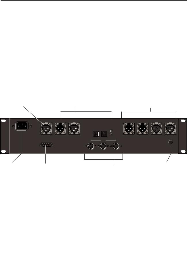
The Rear Panel
Digital Inputs and Outputs
Time Code In
3-pin female XLR connector for input of SMPTE (Drop or Nondrop), EBU, or FILM time code formats. (Electronically balanced, 100mV p-p minimum)
Inputs
Three connectors are provided for digital input:
AES/EBU professional format (1):
3-pin female XLR
S/PDIF EIAJ CP-340 consumer format (2): unbalanced coaxial RCA
optical (fiber-optic)
One of these connectors may be selected for digital input.
Outputs
Output format can be AES/EBU or S/PDIF. Output always goes to all three digital outputs.
Digital interfaces conform to AES 3-1992 (ANSI S4.40-1992). Input/output impedance levels of the AES/EBU connectors comply with the CCITT V.11 EIA RS-422A.
Analog Inputs and Outputs
3-pin XLR connectors, electronically balanced.
Either pin 2 or pin 3 can be used as high but, to maintain polarity when transferring data to the digital domain, pin 2 high convention is used by Lexicon.
Pin 1 and either pin 2 or pin 3 of each output must be grounded for unbalanced operation.
Input impedance is 50kΩ unbalanced, and 100kΩ balanced. Inputs accept input levels from -14dBu to +20dBu.
Output impedance is 75Ω , and levels up to +18dBu are possible.
TIME CODE IN |
DO AES/EBU DI |
EIAJ CP340 |
R OUT |
L OUT |
R IN |
L IN |
|
PUSH |
PUSH |
|
|
|
|
PUSH |
PUSH |
|
|
DO |
DI |
DI |
|
|
|
|
|
|
|
|
|
|
|
|
|
|
|
DO |
|
|
|
INPUT
GAIN
COMM PORT |
MIDI |
|
|
|
|
OUT |
THRU |
IN |
AC Power |
Communications |
Standard 3-pin IEC |
Port |
power connector. |
DE9 LARC connec- |
|
tor. |
MIDI Connectors
Out: Transmits MIDI data to other equipment. Thru: Passes any MIDI data received without change.
In: Receives MIDI information from other MIDI equipment such as master keyboard controllers, MIDI foot controllers, sequencers and synthesizers.
Input Gain
2-position (In/Out) switch for matching input gain to the source being used.
In = +16dB; Out = 0dB.
1-3
Controls and |
|
Connectors |
Lexicon |
Connectors
andCables
Connectors
Signal |
Mating Connector |
Description |
|
L and R Analog |
XLR A3M |
Active balanced, pin 2 high |
|
Audio Input |
|
+2dBu min; +20dBu max |
|
|
|
at 0dB setting |
|
|
|
|
|
L and R Analog |
XLR A3F |
Active balanced; pin 2 high |
|
Audio Output |
|
-2dBu to +18dBu |
|
|
|
at full scale output |
|
|
|
|
|
AES/EBU |
XLR A3M |
Balanced RS-422 |
|
Digital Input |
|
pin 2 high |
|
|
|
|
|
AES/EBU |
XLR A3F |
Balanced RS-422 |
|
Digital Output |
|
pin 2 high |
|
|
|
|
|
SPDIF |
RCA |
Unbalanced 75Ω |
|
EIAJ CP340 |
|
|
|
Consumer Digital |
|
|
|
Input and Output |
|
|
|
|
|
|
|
SPDIF |
See below |
EIAJ Consumer Digital |
|
EIAJ CP340 |
|
Audio format |
|
Consumer Digital |
|
|
|
Audio Optical |
|
|
|
Input and Output |
|
|
|
|
|
|
|
Time Code |
XLR A3M |
Active balanced; pin 2 high |
|
Input |
|
-12dBm to +8dBm operating |
|
|
|
range |
|
|
|
|
|
MIDI In |
5-pin DIN |
Standard MIDI Interface |
|
MIDI Out |
|
|
|
MIDI Thru |
|
|
|
|
|
|
|
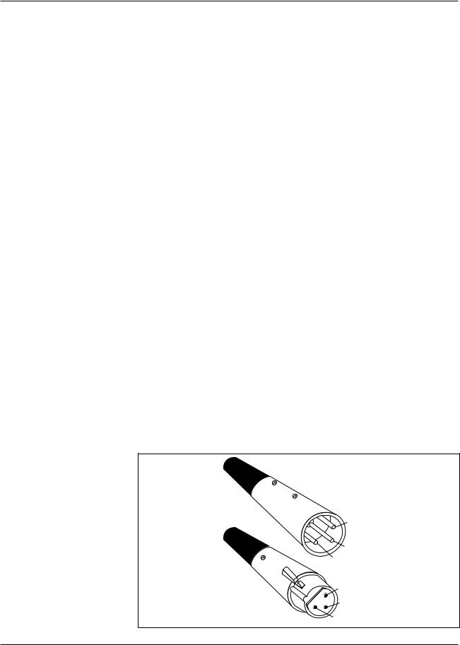
2 = high
Male
3 = low
1 = ground
Female
1 = ground
3 = low
Pin 2 high by convention. |
2 = high |
|
1-4

300L Service Manual
Controls and
Connectors
For best performance, maintain balanced connections, and use high-quality, low-capacitance, twisted-shielded pair cable.
When connecting to a single-ended, unbalanced device, connect the low side to signal ground at the unbalanced piece of equipment.
For mono connection, connect the left and right input channels in parallel.
Be careful to keep input and output to all channels wired consistently. Out-of- phase wiring can produce audible effects.
This interface requires balanced connections using high-quality, low-capaci- tance, controlled-impedance, data communication, twisted-shielded pair cable.
It will not work reliably if microphone cable is used.
This interface is unbalanced but, because it carries digital signals, it requires the use of 75Ω RG-59 coaxial cable.
Use commercially-available, consumer audio optical cable assemblies.
Use standard 5-pin DIN MIDI cable assemblies, available from your local dealer.
Below are recommended manufacturer's part numbers for cable and cable assemblies. In some cases, two types are specified: one with an overall braid shield for heavy use, and one with a foil shield for permanent installation.
Analog Audio and Time Code
Belden 8412 (microphone cable with braided shield)
Belden 9461 (foil shield)
AES/EBU
Belden 9860 (braided shield)
Belden 9271 (foil shield)
Maximum recommended length: 100 ft (30M)
SPDIF (EIAJ CP340) Consumer Digital Audio
Belden 9259 (22 AWG conductor, .242 O.D.)
Belden 8218 (27 AWG conductor, .150 O.D.)
Maximum recommended length: 32 ft (10M)
SPDIF (EIAJ CP340) Consumer Digital Audio Optical
Toshiba TOCP174y
Sony POC-15
Maximum recomended length: 16 ft (5M)
Cables
Analog Audio I/O
and Time Code
AES/EBU
Digital Audio I/O
SPDIF (EIAJ CP340)
Consumer Digital Audio I/O
SPDIF (EIAJ CP340)
Consumer Digital Audio
Optical I/O
MIDI IN, OUT and THRU
1-5

Controls and |
|
Connectors |
Lexicon |
About the LARC
Program Select
Press to enter Program mode. Press repeatedly to scroll through presets in a bank.
Register Select
Press to enter Register mode. Press repeatedly to scroll through registers in a bank.
Slider Display Line
Shows abbreviated names of the parameters currently under the control of the sliders. Full name appears in the Main Display.
Control Sliders
Adjust parameter values.
|
Headroom Indicator |
Main Display |
+12 dBm indicates analog or |
digital clipping. Proper input |
|
Shows names and values for |
level is with +12 dB and ovld |
all selections. |
LEDs unlit. |
|
|
|
|
|
|
|
|
|
L |
|
|
|
|
-24 18 12 |
6 |
0 |
6 +12 ovld dB |
||
|
|
|
|
|
|
|
|
|
R |
|
|
|
1 |
2 |
|
3 |
|
4 |
5 |
PROG |
REG |
|
6 |
7 |
|
8 |
|
9 |
0 |
BANK SETUP |
STO |
CTRL |
MACH |
MUTE ENTER PAGE |
|||||
|
VAR |
|
|
|
|
|
|
|
|
Slider Display Keys
Show parameter name and value in main display. Press twice to engage vernier (fine) adjustment mode when available.
Numeric Keypad
Press one of these keys to load a program selected with PROG or REG. Also used to select pages.
Function Keys
Bank scrolls through groups of programs or registers.
SETUP brings you to the top level of the user interface.
STO stores edited setups and program registers.
CTRL toggles in and out of the control mode.
MACH toggles between machines when Split or Cascade setups are selected.
MUTE toggles the removal and restoration of processed audio from the outputs.
ENTER loads selected setups.
PAGE steps through pages of setup and program parameters.
1-6
300L Service Manual
Controls and
Connectors
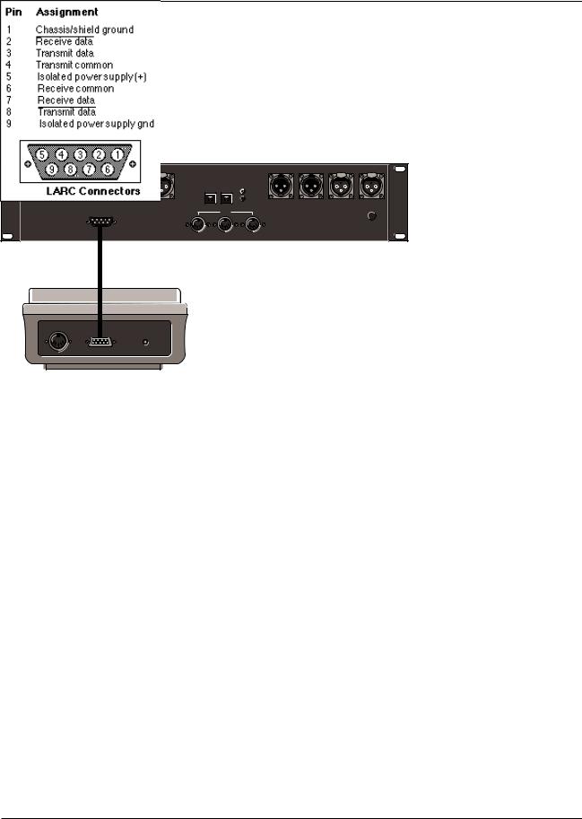
How to Interface the LARC
The 300L rear panel COMM PORT connector interfaces to the Lexicon Alphanumeric Remote Control (LARC) via a flexible 50-ft cable (supplied). The pin assignments for the connector are shown to the right.
TIME CODE IN |
DO AES/EBU DI |
EIAJ CP340 |
R OUT |
L OUT |
R IN |
L IN |
|
PUSH |
PUSH |
|
|
|
|
PUSH |
PUSH |
|
|
DO |
DI |
DI |
|
|
|
|
|
|
|
DO |
|
|
|
INPUT
GAIN
COMM PORT |
MIDI |
|
OUT |
THRU |
IN |
Wiring diagram for the 300L
COMM PORTconnector.
1-7

Controls and |
|
Connectors |
Lexicon |
Setting Analog
Audio Levels
When shipped from the factory, the 300L is set for Analog I/O configuration. Once you have connected the analog inputs and outputs, you should set up the analog input (pre A/D converter) and analog output (post D/A converter) levels.
First, you will need to select a Setup which represents a digital “straight wire” through the box. To do this, press the SETUP key, then use the PRE slider to select Setup Preset 81.
The upper display should read:
L
STEREOADJUST
-24 18 12 6 0 6 +12 ovld dB
SG: SET P 81
R
Press ENTER to load the setup. Press CTRL, then press PAGE, followed by the number 9. This will display Control Mode Page 9. The lower display will show:
IN: |
LFT |
RT |
OUT: |
LFT |
RT |
|
|
|
|
|
|
The I/O structure of the box is specified such that if a +11dBu signal is input into the box, full scale conversion will occur. This is indeed true if the LFT (left) input and RT (right) input sliders are set to 0dB. In fact, with the Output sliders set to 0dB, you should read exactly the same, +11dBu. In practice, analog I/O interface levels vary widely with various console types. The Input and Output controls on page 9 allow the 300L to be optimized for use throughout the analog world.
With the Left and Right sliders fully attenuated to -10dB, the 300L can look at signals as high as +21dBu. For those of you who like to “blast” through an analog console, this full attenuation may be a requirement.
If your console typically sends a +4dBu signal when the send meters read 0VU, the 300L’s input will be left with only 7dB before converter saturation. This is not good. A common rock and roll solution would be a quick trim of the send masters by -7 or -10 dB to give the system a little more “breathing room”. Some analog engineers often refer to this “breathing room” as headroom. Technically , there is no such thing as headroom in a digital system. When the converter goes to full scale, overload will occur. Although this solution will usually work, we suggest you trim the inputs to the 300L.
To do this, move the LFT and RT input sliders to the required settings. You may need to “null” these sliders at their mid-travel points in order to “grab” the default value of +0dB. Attenuate them one at a time and make sure they are matched. Pressing the buttons under each of the active sliders will interrogate the current values.
1-8

300L Service Manual
Controls and
Connectors
Input levels between -1.5dBu and -2.9dBu will reference to 0 on the LARC meters. You will find your own region of optimization.
On the output side, if +11dBu isn’t quite enough oomph! for the return inputs (which is rarely the case) you may need to crank up the outputs. If you have attenuated the inputs, as in the above example, the output will not be at unity gain so you will have to boost the output sliders by the same amount. Grab each slider individually and match the outputs.
A note on metering reverberation programs
Most Setups have the meters set for EFX-OUT. What we have described above is getting the input and outputs “environmentally” matched.
As you start running reverb programs, you will see a natural attenuation on the meters. This is perfectly normal. If the LARC overload LEDs do light up, DSP overload is occurring. This is usually linked to someone’s “aggressive analog behavior”, but there may be other times when an effect running in a delay program has too much feedback and cross-feedback. A common pre-mastering mistake is to run close to the edge going into an EQ process before going digitally into a DAT. Boosting high or low frequencies is likely to overload the DSP output. Be aware!
1-9

Controls and |
|
Connectors |
Lexicon |
Periodic Under normal conditions the 300L requires minimal maintenance. Use a soft,
Maintenance lint-free cloth slightly dampened with warm water and a mild detergent to clean the exterior surfaces of the unit.
Do not use alcohol, benzene or acetone-based cleaners or any strong commercial cleaners.
Avoid using abrasive materials such as steel wool or metal polish. If the unit is exposed to a dusty environment, a vacuum or low-pressure blower may be used to remove dust from the 300L exterior.
Obtaining Factory
Parts and Service
Ordering Parts When ordering parts, identify each part by type, value and Lexicon Part Number. Replacement parts can be ordered from:
Lexicon Inc.
100 Beaver Street
Waltham MA 02154
Telephone: 617-736-0300
Fax: 617-788-0499
ATT: Customer Service
Returning units for service
Before returning a unit for warranty or non-warranty service, consult with Lexicon to determine the extent of a problem and to obtain Return Authorization. No equipment will be accepted without Return Authorization from Lexicon.
If you choose to return a 300L to Lexicon for service, Lexicon assumes no responsibility for the unit in shipment from customer to the factory, whether the unit is in or out of warranty. All shipments must be well packed (using the original packing materials if possible), properly insured, and consigned to a reliable shipping agent. When returning a unit for service, please include the following information:
•Name
•Company name
•Street address
•City, State, Zip Code, Country
•Telephone number (including Area Code)
•Serial number of unit
•Description of the problem
•Desired return date
•Preferred method of return shipment
Please include a brief note describing conversations with Lexicon personnel and give the name and telephone number of the person directly responsible for maintaining the unit.
Do not include accessories such as manuals, cables, etc. with the unit unless specifically requested to do so by Lexicon Service personnel.
1-10

2
Performance
Verification

Performance Verification |
Lexicon |
|
|
|
|
Introduction This section attempts to guide the troubleshooting technician through the process of verifying the proper operation of all of the 300L systems and subsystems. It is assumed that the reader is a qualified technician that is familiar with the operation of the 300L and the required test equipment. A good understanding of how the 300L should behave is essential to debugging a defective system.
Before attempting to perform any of the detailed tests outlined in this document, a list of symptoms should be generated based on user complaints and some basic system tests (listening, etc...). In most cases the technician is not the person who encountered the problem. As a starting point, try to recreate the symptoms on the bench and add your own notes to the original user’s notes. Check the following:
•odor (Do you smell burnt components?)
•mechanical damage (Was the unit dropped or something dropped on the unit?)
•mechanical sounds on power up (You should hear relays click on power up.)
•loose components rattling around inside unit
Verify that all of the troubleshooting tips outlined in the Owner's Manual and at the end of this section have been checked. This will help eliminate any unnecessary service due to operator error. These troubleshooting tips should be tried before attempting to perform the entire Proof of Performance.
2-2

300L Service Manual
Performance Verification
Remove the top cover of the unit as follows: Remove the 3 screws that hold each rack ear. Remove the 3 remaining screws on each side of the unit, screw(s) in the front of the top cover, and 1 screw in the upper center of the rear panel. Remove the cover by gently spreading the bottom of each of its sides and lifting.
Inspect the unit for any obvious signs of physical damage.
Verify that all screws and hardware are tight.
Verify that the fuses on the Power Supply board are not blown. If fuses are replaced, use those indicated in the following table:
LINE |
F1 |
F2 |
F3 |
F5 |
100/120v |
.5A |
.5A |
3.15A |
.500A |
|
5x20 |
5x20 |
5x20 |
3AG |
230v |
.5A |
.5A |
3.15A |
.250A |
|
5x20 |
5x20 |
5x20 |
5x20 |
|
|
|
|
|
Verify that the XLR connector are tight by plugging a connector into each jack.
If the XLR connectors feel loose, tighten them by turning the lock clockwise with the “XLR Lock Screw Driver”.
Check all ribbon cables for proper seating.
Verify that both W4 and W5 on the Host board are in the righthand position (as viewed from the front of the unit). Note: these jumper blocks are not available on Rev. 1 Host boards.
Check all socketed components for proper seating and bent pins.
Verify that fiche paper (protective covering) has been installed on the bottom of the power supply board.
Check the AC power cord for signs of physical damage.
|
|
DSP |
Analog |
Host |
Power |
|
Supply |
|
|
|
Initialization and
Inspection
Initial Inspection
Required Equipment
Clean, antistatic, well-lighted work area.
Male XLR Connector Female XLR Connector
(cable not required, but can be used)
XLR Lock Screw Driver (Neutrix Part #140)
2-3

Performance Verification |
Lexicon |
|
|
|
|
Power Supply
Required Equipment
Clean, antistatic, well-lighted work area
300L Power Cord (Lexicon #680-00841)
Variac or comparable variable AC line source (1Amp)
Digital Multi-Meter (DMM) Oscilloscope (min. 20mHz
with a X10 probe)
To check the 300L's power supplies, remove the top cover as described under Initial Inspection and perform the following tests. (Refer to Power Supply schematics at the end of this manual.)
System Current Draw
Slowly power up the 300L with the Variac to rated line voltage.
Observe the AC line current on the Variac and verify that it is <0.4amps for 100/ 120v or <0.2amps for 220/240v line voltages.
+5V Digital Supply Check
Measure the voltage between pin 2 (+5V) & 6 (DGND) of the cable plugged into J9 on the Host board.
Verify that the voltage is between +4.9VDC and +5.1VDC. If the voltage is outside of this range, adjust R3 on power supply board for +5.00VDC +0.1V.
+12V Supply Test
Measure the voltage between the front of FB (ferrite bead) 4 and the front of R22 on the Host board. Verify that the voltage is between +11.40 and +12.60VDC.
-12V Supply Test
Measure the voltage between the front of FB3 and the front of R22 on the Host board. Verify that the voltage is between -11.40 and -12.60VDC.
+15V Supply
Measure the voltage from the +15V pin of J2 on the Analog board to the left side of C6 (analog ground). Verify that the voltage is +14.25 to +15.75VDC.
-15V Supply
Measure the voltage from the -15V pin of J2 on the Analog board to the left side of C6. Verify that the voltage is -14.25 to -15.75VDC.
+5VA Supply
Measure the voltage from the +5VA pin of J2 on the Analog board to the left side of C6. Verify that the voltage is +4.75 to +5.25VDC.
-5VA Supply
Measure the voltage from the -5VA pin of J2 on the Analog board to the left side of C6. Verify that the voltage is -4.75 to -5.25VDC.
Battery
Power down the unit. Measure the voltage across BAT 1 on the Host board. Verify that the voltage is >2.5VDC.
2-4

300L Service Manual
Performance Verification
Set the DMM for 750VAC and attach the probes to the blue and brown wires at Power Fail the AC receptacle on the 300L.
Reduce the AC line voltage. Verify that the AC line voltage is above the -25% voltage, and below the -15% voltage for the appropriate nominal line voltage as shown in the following table.
Nominal |
-25% |
-15% |
100VAC |
- 75VAC |
85VAC |
120VAC |
- 90VAC |
102VAC |
220VAC |
- 165VAC |
187VAC |
230VAC |
- 100VAC |
216VAC |
|
|
|
Return the AC line voltage to the nominal level.
Verify that W4 and W5 on the Host board are in the righthand position (as viewed Timecode Tests from the front of the unit).
Connect the XLR cable from the Time Code output of the timecode generator to the Time Code input on the 300L.
On the LARC, press CTRL, Page, then 7. The upper display should read:
TIMECODE
DISABLED
Move the slider labeled OFF until the upper display reads:
SNAP =
00: 00: 00: 00
Set the timecode generator for “SMPTE DROP-FRAME.
Verify that the unit displays “SD— V” to indicate that it has identified the incoming time code as SMPTE Drop and the timecode continues to increment on the lower display of the LARC.
Set the timecode generator for “EBU”.
Verify that the unit displays “—E-V” to indicate that it has identified the incoming time code as EBU and the timecode continues to increment.
Set the timecode generator for “FILM”.
Verify that the unit displays “—FV” to indicate that it has identified the incoming time code as FILM and the timecode continues to increment.
2-5
Performance Verification |
Lexicon |
|
|
|
|
Listening
Required Equipment
Clean, antistatic, well-lighted work area
Low Distortion sine wave oscillator
Headphone Amplifier Bong/click generator
2 Audio cables w/ female XLR connectors on one end and connectors to fit the bong/click generator and the oscillator on the other end.
2 Audio cables w/ male XLR connectors on one end and connectors to fit the headphone amp at the other end.
Stereo Headphones
Setup
1.Connect the left and right outputs of the oscillator to the left and right inputs of the 300L.
2.Connect the left and right audio outputs of the 300L to the left and right inputs of the headphone amp.
Note: When performing the Listening tests with unbalanced equipment, short pin 3 to pin 1 of cables connected to the analog input and output connectors.
3.Set the oscillator to 200Hz @ about -20dBV.
4.Turn volume control on amplifier all the way to minimum.
5.Attach headphones to amplifier’s headphone jack.
6.Set the input gain switch on the rear panel of the 300L to the OUT position.
7.Turn on the amplifier.
8.Turn on the 300L. The LARC should go through its power up display sequence and then display:
LARGE HALL
If LARGE HALL is not displayed at the end of this sequence, press BANK, 1, PROG, 1 on the LARC to load the Large Hall program.
9. Press CTRL to display:
CONTROL MODE
PAGE 1
If Page 1 is not displayed, press PAGE, then press 1.
10. Adjust slider 2 (labeled CLK) until the display reads:
CONTROL MODE
ANALOG 44K
Listen
1.Put on the headphones and slowly increase the amplifier volume to a comfortable listening level.
2.Verify that the output of the unit is free of converter artifacts (grit, buzz, static, etc.).
3.Listen to the reverb decay time for any break up or pops.
4.Turn off the oscillator and connect a bong/click generator. Play a bong through the 300L and check the reverb again.
5.Press CTRL to return to Control mode, set the CLK slider to select 48K and repeat the listing test.
Storing Registers*
Modify one of the system presets and store it in a user register.
Load another preset.
Power cycle the system (OFF/ON).
Reload the modified effect from the user registers and verify that it sounds the same as it did when it was stored.
* Refer to the 300L Owner's Manual for operational instructions.
2-6

300L Service Manual
Performance Verification
Connections
Connect the 600Ω resistor to the input of the distortion analyzer.
Connect the audio cable with the male XLR between the oscillator output and the left input of the 300L.
Connect the audio cable with the female XLR between the distortion analyzer input and the left output of the 300L.
The following sections attempt to describe analog performance verification in generic terms which can be applied to most types of audio tests. These sections can also be used as a reference when troubleshooting failure of an Audio Precision ATE test.
Setup
Power on the 300L.
Load the Stereo Adjust program by pressing BANK, 9, PROG, 1 on the LARC.
Press CTRL, PAGE, 9.
Audio Proof of
Performance
Required Equipment
Clean, antistatic, well-lighted work area
Low Distortion audio oscillator <0.01% THD
Distortion Analyzer that can measure <0.01% THD and perform level measurements in dB
*Balanced audio cable with a male XLR on one end and the appropriate connector on the other end for the oscillator output. Pin 2 on XLR is hot.
600Ω resistor
*Balanced audio cable with a female XLR connector on one end and the appropriate connector on the other end for the distortion analyzer input. Pin 2 on XLR is hot.
*NOTE: If the audio oscillator and/or the distortion analyzer do not have balanced audio connections, configure the appropriate XLR connectors so that pins 1 and 3 are ground and pin 2 is hot.
2-7

Performance Verification |
Lexicon |
|
|
|
|
Level Test
Frequency
Response
Noise
THD
Crosstalk
If necessary, adjust the appropriate sliders on the LARC so that input and output levels are set to 0.00dB.
Set the oscillator for 0dBu output @1kHz and the distortion analyzer to measure level in dB.Verify the output level is between +1dB and –1dB.
Take a 0dBr reference. On the LARC, adjust the slider labeled Left Input until it displays–10.00dB, and verify the output level is between –9.00 and –11.00dB.
Adjust the slider to display +10.00dB, and verify the output level is between +9.00 and +11.00dB.
Adjust the slider until it displays 0.00dB, then repeat the above procedure for the slider labeled Left Output.
On the distortion analyzer, disable all filters. Vary the oscillator frequency from 20Hz to 20kHz and verify that the output level remains between +0.20dB and -.20dB at all frequencies.
Enable the lowpass filter (10Hz-20kHz) if available.
Turn the oscillator off, and set the level meter on the distortion analyzer to measure <–80dB. Verify that the reading is <–78dB.
Turn the oscillator on and set the distortion analyzer to measure THD at the .01% range and at a level range where it can measure 11dB. Set the oscillator for 11dBu output @ 1kHz and verify that the reading on the distortion analyzer is <0.01%.
Transfer the 300L audio cable connection to the right input and set the distortion analyzer to measure a level of –80dB. Verify that the reading is <–80dB.
Set the oscillator for frequencies of 10kHz, 20kHz and 1kHz and verify the analyzer reading is <–80dB at each frequency.
Set the oscillator for a frequency of 1kHz and the distortion analyzer to measure a level of 0dB.
Transfer the 300L audio cable connections to the other side and repeat the frequency response, noise, THD and crosstalk tests.
2-8

300L Service Manual
Performance Verification
Power the 300L off, then on and verify that the following display sequence Power Up appears on the LARC:
LEXICON
MAINFRAME
RESET
LEXICON
300L VX.XX
LARGE HALL
SG:SET P 1
If the program LARGE HALL is not displayed at the end of the power up sequence, press BANK, 1, PROG, 1, to load the LARGE HALL program. Put on the headphones and slowly increase the amplifier volume until it's at a comfortable listening level.
TO PREVENT DAMAGE TO THE UNIT, KEEP ONE CORNER TOUCHING THE WORK SURFACE AT ALL TIMES.
Shock
Lift each corner of the 300L four (4) inches off of the worksurface and drop it. Verify that no audio intermittence occurs during this action.
On the LARC, press CTRL, then 1 to display:
CONTROL MODE
PAGE 1
Press the button below the slider labeled CLK and verify that the LARC upper display reads:
SAMPLE RATE
ANALOG 48K
Move the CLK slider to its topmost position, then to the bottom of its range until the display reads:
SAMPLE RATE
ANALOG 44K
Lift each corner of the 300L four (4) inches off of the worksurface and drop it. Verify that no audio intermittence occurs during this action.
Inspect all visible components to make sure nothing has loosened, then press PAGE, 3 to display:
CONTROL MODE
PAGE 3
Adjust the slider labeled COPY until the upper display reads: COPY PROTECT
OFF
Press CTRL. The upper display should read: LARGE HALL
300MA: B01 P1
2-9

Performance Verification |
Lexicon |
|
|
|
|
DSP Board
Troubleshooting
Cable Connections
The DSP board in the 300L cannot be troubleshot in the field. Contact Lexicon Customer Service if symptoms indicate DSP board failure.
The 300L contains a lot of cables and connectors, which naturally have a lower overall reliability than raw PC boards or components. Vibration can eventually break the strands of cables making them intermittent or even open. Connections can become oxidized, corroded or contaminated with flux and become intermittent, open or resistive. In addition to these “natural” dangers of cables/connectors, poor seating at assembly can reduce the long term reliability of the connection.
For all of these reasons, caution should be used when troubleshooting 300Ls. Before any cables are removed, they should be carefully inspected for proper seating and continuity between the following points.
|
|
|
for reference only |
|
Host |
to |
DSP |
(J6/J9 pin |
Signal) |
U18 pin 2 |
|
U46 pin 19 |
45 |
D0 |
3 |
|
18 |
47 |
D1 |
4 |
|
17 |
49 |
D2 |
5 |
|
6 |
51 |
D3 |
6 |
|
15 |
53 |
D4 |
7 |
|
14 |
55 |
D5 |
8 |
|
13 |
57 |
D6 |
9 |
|
12 |
59 |
D7 |
U33 pin 10 |
|
U52 pin 2 |
7 |
SLVST/ |
U32 pin 14 |
|
U45 pin 11 |
6/7 pin 15 |
SLVCSR |
U25 pin 46 |
|
U52 pin 5 |
1 |
A0 |
U39 pin 3 |
|
U45 pin 1 |
J6/7 pin 7 |
RESET/ |
These are the minimum connections required to test the control lines from the Host to the DSP. If these lines are showing continuity and you are still getting errors on power up, there is probably a legitimate problem with the circuitry, but you should still carefully inspect each cable before, during and after removal.
2-10

300L Service Manual
Performance Verification
When troubleshooting any kind of equipment, intermittent problems are among Audio Problems the most difficult to trace. The first step when troubleshooting any problem is to
collect as much information as possible. The following table outlines some basic questions which should be answered before attempting to troubleshoot an audio problem with the 300L:
Does the problem occur...
1.on one output only?
2.at certain signal frequencies only?
3.at certain signal level only?
4.in certain programs only?
5.at certain sample frequencies only?
6.with input only?
7.without input only?
8.temperature or shock sensitive?
In general, it is best to run all of the audio proof-of-performance tests to further isolate the problem within the system. This can be vital when troubleshooting subtle problems. While some system failures may cause a variety of tests to fail, troubleshooting based on one type of symptom may be much easier than another. For example, a bad capacitor may produce a high level of distortion and a frequency response problem. The frequency response problem would be easier to trace because the signal level can be monitored on an ordinary oscilloscope.
Probably the most useful piece of information is to determine whether the |
One Channel Bad |
problem is on both channels or on only one. If the problem is occurring on one |
|
output only, the following assumptions can be made with some level of |
|
confidence: |
|
The power supplies are OK. |
|
The system timing (clocks) is O.K. |
|
The digital circuitry up to the oversampling filters is O.K. |
|
These types of problems can be fairly easy to troubleshoot, as the working |
|
channel can be used as a reference. With the same signal applied to both inputs, |
|
compare the signal on both channels at various points along the analog signal |
|
path. This may localize the problem fairly quickly. |
|
The fact that the problem is occurring in both channels can be equally revealing. |
Both Channels Bad |
The likelihood that the two separate components failed in the same way at the |
|
same time is fairly remote. The problem can probably be traced either to a |
|
component which is common to both channels, or to a system problem such as |
|
a power supply or timing problem. If there is no output, refer to that section for |
|
more troubleshooting information. |
|
A unit with no output can be one of the easiest to troubleshoot. The reason for |
No Output |
this is very straightforward: the symptom is easy to see.— .no signal. Again, |
|
determining whether one or both channels is bad can reduce the number of |
|
suspected circuits dramatically. (See the previous sections.) |
|
When the system under test has no output from only one channel, the |
|
problem can usually be easily traced by feeding a sine wave into both inputs and |
|
comparing the left and right signals at various points in the circuit. |
|
2-11

Performance Verification |
Lexicon |
|
|
|
|
No Output, cont'd.
No output with no relay click on power up
Effects don’t sound the same as when they were stored
The LARC control head will not light
Touching a LARC
slider resets unit
Note that from the A/D chip output to the oversampling chip on the DSP board the left and right are combined into a single serial audio data stream. Any problems related to one channel only will probably not occur in this circuitry.
When the system under test has no output from either channel, the first thing to check is the +15V power supplies on the Analog board. Verify that they are within the specified voltage ratings. (See the proof-of-performance section.) If they are OK, feed a sinewave into both inputs and check for signal at the output of the A/D converter chip (U6 pin 16). If there is signal present, follow the signal path indicated earlier in this section. If there isn’t signal present, check the +5VA, -5VA and +5VD supplies at the A/D chip. If they are active check for the CHSEL (sample clock), XCLK and BCLK clocks and follow the signal path back toward the inputs.
If the +15V supplies on the Analog board are down with F1 and F2 on Power Supply board blown, a problem on the Analog board is causing the fuses to blow. Check the +15v supplies for shorts. Replace fuses (if blown), power up the system and carefully check the MDACs for heat. A hot MDAC is usually bad and will pull down the +15v supplies.
Effects that don’t sound the same as when they were stored can be caused by a number things. To help localize the problem several preliminary tests should be performed. Verification of the system’s ability to store and generate an effect can usually be done by creating an effect, storing it, power cycling the unit several times and checking the effect. If the effect has noticeably changed, the problem is probably in the Host board’s static RAM (U21) or the battery circuitry. If the effect seems unchanged, the fault may be in the DSP processors and the audio signal path itself.
Because the analog circuitry and the DSP processors are both in the audio signal chain, the two circuit groups must be divided using the BYPASS control. Load the “Stereo Adjust” preset and listen for distortion or audible artifacts at the 300L output . Put the unit into BYPASS and listen again. If the artifacts disappear, the problem is probably on the DSP board. If the artifacts remain, the problem is probably on the Analog board. In any case, you should check the sample clock (CHSEL at pin 14 of U6 on the Analog board) for the correct sample frequency (default in diagnostics is 48kHz). The sample clock (and all of the converter clocks) are generated on the Host board.
Verify +20VDC at TP1 on motherboard and pin 5 of either LARC port on the 300L rear panel. If +20 volts is getting to the LARC, proceed to troubleshoot the LARC. (The LARC only needs power to operate.)
Check U11 on LARC (Signetics 4515s have proven to be unreliable. Replace with RCA or other brand.
2-12

300L Service Manual
Performance Verification
This section contains detailed descriptions of Audio Precision automated tests for the 300L (version 3.50 or higher software). Although these tests will be most useful for repair facilities with Audio Precision test equipment, it should be noted for facilities without this equipment, that these descriptions cover the basic information necessary to create similar tests with alternate audio test equipment. Note: The procedures and utilities used by Lexicon are not included. Users may develop their own procedures, or contact Lexicon Customer Service. Lexicon may elect to share these tools with authorized service centers, but will not provide support to their use.
Most of the audio tests for the system are part analog and part digital. In general input circuitry up to the A/D converter use the analog GENERATOR portion of the Audio Precision to provide stimulus for testing and perform the actual evaluation on the digital audio output (AES). Output circuitry from the D/A converter onward uses the digital audio input (AES) for stimulus and performs the actual evaluation on the analog outputs from the 300L using the Audio Precision’s ANALYZER.
All of the A/D and D/A tests use the Audio Precision DSP program GENANLR.DSP to perform digital audio tests. At the beginning of the procedure, the GENANLR.DSP program is copied onto the PC RAM to improve the speed performance of the procedure. All of the tests in the procedure call the DSP program from the d:\ drive.
In order to automate the system test procedure a special mode was added to the system software to allow the 300L to be controlled via MIDI (see APPENDIX A for a list of commands). Two basic operating modes can be called which allow the system components to be tested:
Analog I/O: Data from the AD chip is routed to both the D/A chips and the digital audio output (A/D testing).
Digital I/O: Data from the digital audio input is routed to boththe D/A chips and the digital audio output (D/A testing).
In Digital I/O mode, the 300L must derive its system word clock from the incoming digital audio for proper synchronization.
The 300L ATE Tests consist of a series of Audio Precision “TESTS” which are sequentially executed by an Audio Precision “PROCEDURE”. The tests attempt to qualify the 300L as thoroughly as possible in as little time as possible.
These procedures make use of a MIDI (Musical Instrument Digital Interface) interface card (MPU 401 compatible) installed in the Audio Precision PC. The MIDI interface is used in the 300L Automated System Test procedure to send control changes into the 300L under test. The control changes messages set the 300L to the proper operating mode for the given test. In order to transmit these commands from an Audio Precision procedure, a DOS command: APUTIL M, was developed by Lexicon to capture any hex data entered on the command line after the command and transmit it as MIDI data (i.e. APUTIL M f0 06 <Enter>). In the 300L procedure, MIDI commands are used extensively to set up the unit under test. APPENDIX A outlines the MIDI commands used in the procedure and their applications. These commands are entered in the procedure in the form: DOS APUTIL M f0 06 07 00 00 03 00 00 00 f7.
Audio Precision ATE
Test Descriptions
Required Equipment
Audio Precision System 1
(with PCI card)
SYS-22 “A” for Analog Only Testing
SYS-322 “A” for Full Digital I/O Testing
IBM PC (or compatible) with a hard disk (see S1 manual for details)
Audio Input and Output cables (see the appropriate section)
ATE Tests
MIDI Automation
2-13

Performance Verification |
Lexicon |
|
|
|
|
Error Handling/ Data Collection (Lexicon procedure)
If a test fails, the procedure will display a failure message and present the following options:
View the failure
Quit to Audio Precision menu Quit to DOS
Continue
If you choose to view the failure, the data will be printed after viewing the failure and give you another chance to quit to the Audio Precision command menu by typing <F1> or to quit to DOS by typing <ESC>. If you choose to continue, the data will be printed immediately. In these cases, any subsequent tests will also fail depending on the extent of the problem. Generally, if 2 or 3 tests fail, the test should be halted and the unit debugged.
If the unit passes a given test, the procedure will continue on to the next test. All test data can be saved and copied into the PASS directory on the data disk (A:\). When the test procedure is completed, you will be prompted to select the data handling option. Press <SPACEBAR> to test another unit, <F1> to return to Audio Precision Menu or <ESC> to quit all testing. The data handling options available depend on whether the unit passed or failed. When a unit fails one or more tests, the following options are available:
1.Print all FAILED DATA to the printer only.
2.Save FAILED DATA as a file (serial #).PRN to “ERROR PATH”.
3.Print all tests, pass and fail.
4.Save all tests good or bad as file (serial #).PRN to error path
5.View ERROR file D:\ERROR.PRN
6.View PASS file D:\OKDATA.PRN
Make selection or press <SPACEBAR> for none. (Because the procedure automatically prints out the ERROR data for any tests that fail, the most common option taken is <SPACEBAR>. )
When a unit passes all tests, the following options are available:
1.Print all PASSED data to printer only.
2.Save data as file test (Serial #).PRN to A:\PASS\
3.Print custom report and save data as file (Serial #).PRN to A:\PASS\.
4.View PASS FILE D:\OKDATA.PRN
Make selection or press <SPACEBAR> for none.
Tests which use a STEREO SWEEP will produce a printout with test results from the left channel on the left and test results from the right channel on the right as indicated in the following example:
dBu |
%THD |
%THD |
-20 |
0.006 |
0.233 |
/\ |
/\ |
/\ |
GEN (oscillator) |
Left Channel |
Right Channel |
The following sections outline each of the Audio Precision “TESTS”, list the pass fail limits and indicate the associated file names.
2-14

300L Service Manual
Performance Verification
Unless otherwise stated, the following settings will be used on all of the Audio |
Default Settings |
|||
Precision tests: |
|
|
|
|
Generator |
|
Analyzer |
|
|
WAVEFORM |
SINE |
BP/BR FREQ |
AUTO |
|
OUTPUT |
BAL |
DETECTOR |
AUTO RMS |
|
|
50Ω |
FILTER |
OFF |
|
|
FLOAT |
BANDWIDTH |
0Hz 22kHZ |
|
|
|
INPUTS |
100kΩ |
|
|
|
RANGE |
AUTO |
|
DSP: |
|
|
|
|
FILTER |
OFF |
|
|
|
TUNING |
GEN |
|
|
|
DETECTOR |
AUTO |
|
|
|
RATE |
48kHz |
|
|
|
NPUT |
SERIAL |
|
|
|
|
CH-1 A |
|
|
|
|
CH-2 B |
|
|
|
OUTPUT |
D/A OFF (for A/D tests) |
|
|
|
|
SERIAL A&B (for D/A tests) |
|
|
|
When the procedure is first loaded via a batch file, it prompts the operator to |
Setup |
|||
setup the system as shown (see fig.1). |
|
|
|
|
LEXICON M300L ATE TEST PROGRAM
Power up the 300Land connect it to be tested as follows:
Analog Outputs |
A |
— > |
A |
Analog Inputs |
|
B |
— > |
B |
300L |
AES Out |
–> A Out 1 -> |
AES In (AP) |
||
S/PDIF Out |
— >SWR122F 2 |
|
|
|
AES OUT |
|
— > |
AES IN |
|
SPDIF Out |
|
— > |
SPDIF In |
|
AES Out |
|
— > |
AES In |
|
Optical Out |
A |
— > |
A |
Optical In |
Optical Out |
B |
— > |
B |
Optical In |
AP MIDI OUT |
|
— > |
300L MIDI IN |
|
300L MIDI THRU |
|
— > |
APMIDI IN |
|
Press <Enter> on the A.P. keyboard when ready to continue
The APUTIL M T command is a self contained test for MIDI THRU and wrap MIDI THRU Test around. The MIDI OUT cable is connected to the MIDI IN connector on the 300L,
which reproduces the message at its MIDI THRU jack. The PC reads and verifies the message back through it’s MIDI IN cable which is connected to the 300L MIDI THRU jack. With the cables from the PC properly connected to the 300L, the test is easily run by entering the command APUTIL M T F8 (or any other byte except FF) in the Audio Precision’s DOS mode or from the PC’s command line.
2-15
 Loading...