


Walkerflex®
Modular Wiring System
I N S T A L L A T I O N I N S T R U C T I O N S
Installation Instruction No.: 1 006 507 R6 – Updated August 2011
Wiremold electrical systems conform to and should be properly grounded in compliance with requirements of the current National Electrical Code or codes administered by local authorities.
All electrical products may present a possible shock or fire hazard if improperly installed or used. Wiremold electrical products may bear the mark as UL Listed and/or Classified and should be installed in conformance with current local and/or the National Electrical Code.
IMPORTANT: Please read all instructions before beginning.
Products Covered: FCA, NWC, NCS, NCW, NCBS, NPA, NDU, RECDU, CAP3456, CAP810, LDU, LWC, LPA, LCBS, LCW, WWC, WCS, WCW, WPA, WCBS, WDU
NOTE: Label on product indicates which products are suitable for use in air handling spaces in accordance with Sec. 300-22(C) of the National Electric Code.
1.Each Walkerflex® component contains a unique connector key and color indicating rating, conductor location and orientation. Only like color keys can be mated. See Key Configuration and Color Chart for available options.
2.Each Walkerflex® key is comprised of one or more configurations that determine the number of line and neutral conductors. Only identical configurations can be mated. See Key Configuration and Color Chart for available options.
3.Disconnect power from source prior to wiring any Walkerflex® component into building’s electrical power system.
4.Installer to determine maximum cable length based on wire gauge and circuit load.
5.Installer to ensure adequate overload protection based on system key, rating and circuit load.
NDU/LDU (Distribution Unit)
NOTE: Cap Unused Connectors On
All Power Out Modules.
6.Refer to appropriate Wiring Diagram and System Key Configuration Conductor Location Chart for field connections of Cat. Nos. NWC/LWC (Wire Connector) and NCW/LCW (Cable Whips). Refer to wiring diagram supplied with NDU/LDU (Distribution Unit) for field termination.
7.Securing and Supporting of Cables and Components: Refer to NEC Article 604, Manufacturing Wiring Systems and any local codes.
8.Cap all unused connector openings with Cat. No. CAP3456 (for 3 through 6 wire system) or Cat. No. CAP810 (8 and 10 wire system).
9.277V Walkerflex components are only available in 3-6 wire configurations.
10.The Walkerflex system is compatible with the Convia enabled Walkerflex system of the same configuration and key.
P |
|
|
o |
|
|
|
w |
|
O |
|
e |
|
r |
|
ut |
|
|
P |
|
|
|
o |
|
|
|
w |
|
|
|
|
e |
|
|
I |
r |
P |
|
n |
|
|
|
|
|
o |
|
|
|
w |
|
|
|
|
e |
|
|
I |
r |
|
|
n |
|
CAP3456/CAP810
(End Cap)
Secure Box
in Place
Fee |
|
|
dP |
|
|
O |
o |
|
w |
||
ut |
|
e |
|
r |
|
Connected to
Protected Circuit(s)
P |
|
|
o |
|
|
|
w |
|
O |
|
e |
|
r |
|
ut |
|
|
Cat. No. NCS/LCS/WCS
(Cable Set)
TYPICAL WALKERFLEX SYSTEM INSTALLATION
Cat. No. NWC/LWC/WWC
(Wire Connector)
|
|
CAUTION: Do not make or break |
|
Cat. No. NPA/LPA/WPA |
connections while |
|
(Power Adapter) |
circuits are energized. |
Current Flow |
|
|
Direction |
Cat. No. NCS/LCS/WCS |
|
|
(Cable Set) |
|
|
Current Flow |
Cat. No. NCBS/LCBS/WCBS |
|
(Splitter) |
|
|
Direction |
|
|
Current Flow |
|
|
Direction |
|
Current Flow
Direction
Cat. No. NCW/LCW/WCW
(Cable Whip)
Mate only identical Keys and Configurations.
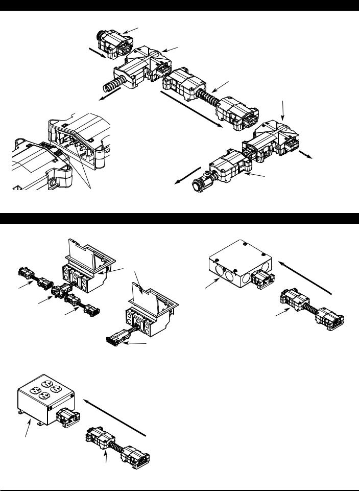
WALKERFLEX SYSTEM ACCESSORIES (120V Only)
TYPICAL PREWIRED ACCESS FLOOR BOX INSTALLATIONS |
WALKERFLEX FURNITURE FEED DISTRIBUTION UNIT |
Access |
Current Flow |
Floor Box |
|
|
Direction |
Cat. No. NCS |
Cat. No. NDUXXXFF |
(Cable Set) |
(Furniture Feed) |
Cat. No. NPA |
|
(Power Adapter) |
|
Cat. No. NCS |
Cat. No. NCS |
(Cable Set) |
(Cable Set) |
|
Cat. No. NCW |
|
(Cable Whip) |
WALKERFLEX RECEPTACLE DISTRIBUTION UNIT |
|
Cat. No. RECDU
(Receptacle Unit)
NOTE: Not suitable for use in Air Handling Spaces.
Current Flow |
NOTE: All Walkerflex accessories are available in |
|
Direction |
||
both the 3-6 and 8-10 pin systems with the |
||
|
||
|
exception of NPA/LPA/WPA which is only |
|
|
available for the 3-6 pin system. |
Cat. No. NCS
(Cable Set)
2

WALKERFLEX SYSTEM ACCESSORIES
RC4ATCAL222PA |
C6STCP222PA |
|
|
|
|
|
|
AV3ATCAL111PA |
4FFATCAL422CW |
||||||||||||||||||||||
|
|
|
|
|
|
|
|
|
|
|
|
|
|
|
|
|
|
|
|
|
|
|
|
|
|
|
|
|
|
|
|
|
|
|
|
|
|
|
|
|
|
|
|
|
|
|
|
|
|
|
|
|
|
|
|
|
|
|
|
|
|
|
|
|
|
|
|
|
|
|
|
|
|
|
|
|
|
|
|
|
|
|
|
|
|
|
|
|
|
|
|
|
|
|
|
|
|
|
|
|
|
|
|
|
|
|
|
|
|
|
|
|
|
|
|
|
|
|
|
|
|
|
|
|
|
|
|
|
|
|
|
|
|
|
|
|
|
|
|
|
|
|
|
|
|
|
|
|
|
|
|
|
|
|
|
|
|
|
|
|
|
|
|
|
|
|
|
|
|
|
|
|
|
|
|
|
|
|
|
|
|
|
|
|
|
|
|
|
|
|
|
|
|
|
|
|
|
|
|
|
|
|
|
|
|
|
|
|
|
|
|
|
|
|
|
|
|
|
|
|
|
|
|
|
|
|
|
|
|
|
|
|
|
|
|
|
|
|
|
|
|
|
|
|
|
|
|
|
|
|
|
|
|
|
|
|
|
|
|
|
|
|
|
|
|
|
|
|
|
|
|
|
|
|
|
|
|
|
|
|
|
|
|
|
|
|
|
|
|
|
|
|
|
|
|
|
|
|
|
|
|
|
|
|
|
|
|
|
|
|
|
|
|
|
|
|
|
|
|
|
|
|
|
|
|
|
|
|
|
|
|
|
|
|
|
|
|
|
|
|
|
|
|
|
|
|
|
|
|
|
|
|
|
|
|
|
|
|
|
|
|
|
|
|
|
|
|
|
|
|
|
|
|
|
|
|
|
|
|
|
|
|
|
|
|
|
|
|
|
|
|
|
|
|
|
|
|
|
|
|
|
|
|
|
|
|
|
|
|
|
|
|
|
|
|
|
|
|
|
|
|
|
|
|
|
|
|
|
|
|
|
|
|
|
|
|
|
|
|
|
|
|
|
|
|
|
|
|
|
|
|
|
|
|
|
|
|
|
|
|
|
|
|
|
|
|
|
|
|
|
|
|
|
|
|
|
|
|
|
|
|
|
|
|
|
|
|
|
|
|
|
|
|
|
|
|
|
|
|
|
|
|
|
|
|
|
|
|
|
|
|
|
|
|
|
|
|
|
|
|
|
|
|
|
|
|
|
|
|
|
|
|
|
|
|
|
|
|
|
|
|
|
|
|
|
|
|
|
|
|
|
|
|
|
|
|
|
|
|
|
|
|
|
|
|
|
|
|
|
|
|
|
|
|
|
CRFBAC2111PA |
AF2KC2111PA |
AC8104YC2111PA |
SAFKC2111PA |
EFB6S |
EFB8S |
EFB10S |
EFBFF |
3
 Loading...