


6ATC
Wiremold electrical systems conform to and should be properly
grounded in compliance with requirements of the current National
Electrical Code or codes administered by local authorities.
All electrical products may present a possible shock or fire
hazard if improperly installed or used. Wiremold electrical products
may bear the mark as UL Listed and/or Classified and should
be installed in conformance with current local and/or the National
Electrical Code.
Evolution™Series
8" Poke-Thru Devices
I N S T A L L A T I O N I N S T R U C T I O N S
Installation Instruction No.: 1 007 156 R2 – Updated May 2010
Products Covered: 8ATCP, 8ATP, 8ATC, 8AT, 8STC, 8CTC, 8CT, 68REC, 68MAAP, 682A, 68B, 8DP, 8DEC, 8S1, 8S2,
8MAAP, 8AAP, 8B, 8TS, 8STCP, 575CHA, 575PTHA, 575BLH, 175CHA, 1125CHA, 1PTHA, 1BLH, 22CHA, CE8STCP
CAUTION: DO NOT operate tile stripper, cleaning, or resurfacing equipment over top of covers. This may result in
damage to the surface finish of the product.
Suitable for use in air handling spaces in accordance with Sec. 300-22 (C) of the National Electrical Code.
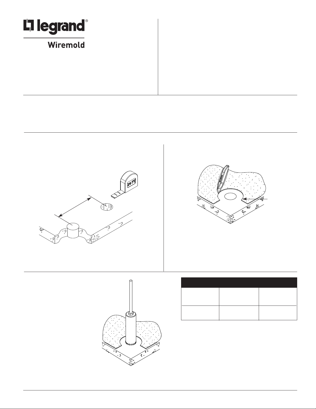
FLOOR PREPARATIONS
Step 1 Layout and locate position of hole(s).
CAUTION: Minimum spacing of 2ft on center and not more than
one device per each 65 square feet of floor area in
each span.
IMPORTANT: Please read all instructions
before beginning.
Step 2 Remove 8 1/2" dia. [216mm] section from
carpet or tile. Use template provided.
24" [610mm] Min
Center – Center
CAUTION: Be certain to locate hole at least 8" [203mm] from any wall or
pillar to leave enough room for Poke-Thru cover assembly.
Step 3 Create core hole according to the
dimensions provided in the chart.
8 1/2"
[216mm]
FLOOR CORE CORE
TYPE SIZE (Min.) SIZE (Max.)
Covered Floors 8" [203mm] 8 1/8" [206mm]
(Carpet, Tile or
Wood)
Bare Concrete 8 1/16" [205mm] 8 1/8" [266mm]
or Terrazzo
1
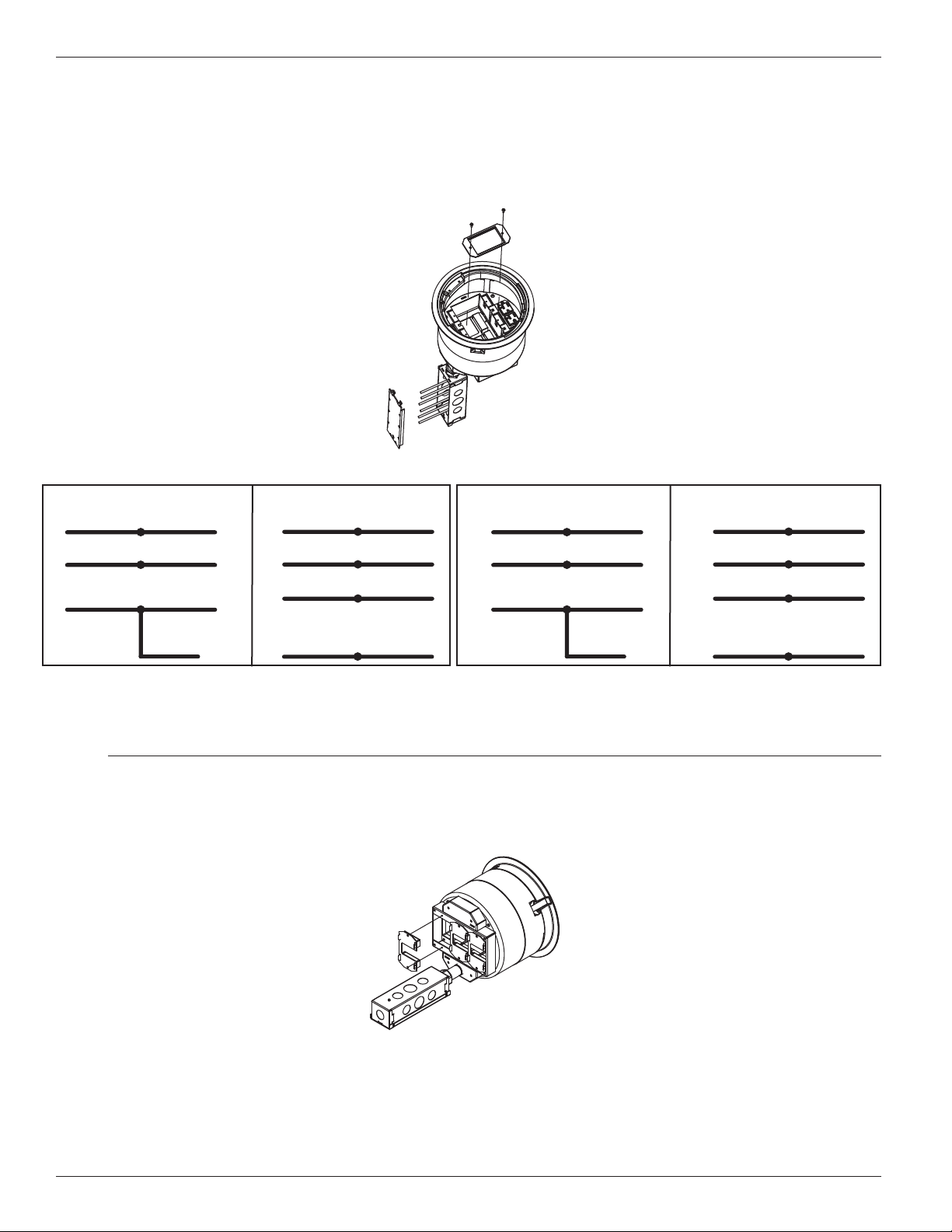
INSTALLING COMPLETE ASSEMBLY
Step 1 Attach data and AV plates and wire power and data devices (Can be completed above floor).
Refer to wiring schematic below for power wiring options.
Catalog Nos. 8ATCP, 8ATP
ircuit B Wiring
Circuit A Wiring
C
ONVENTIONAL WIRING SCHEMATIC ISOLATED GROUND WIRING SCHEMATIC
C
BLACK or HOT BLACK BLACK or HOT BLACK
From branch circuit from Poke-Thru receptacle From branch circuit from Poke-Thru receptacle
HITE or NEUTRAL WHITE WHITE or NEUTRAL WHITE
W
From branch circuit from Poke-Thru receptacle From branch circuit from Poke-Thru receptacle
GREEN or GROUND GREEN ISOLATED GROUND GREEN
rom branch circuit from Poke-Thru receptacle From branch circuit from Poke-Thru receptacle
F
System Ground
GREEN (jumper wire)
from Poke-Thru
junction box
GREEN or GROUND
rom branch circuit from Poke-Thru
F
System Ground junction box
GREEN (jumper wire)
ONVENTIONAL WIRING SCHEMATIC ISOLATED GROUND WIRING SCHEMATIC
C
BLACK or HOT RED BLACK or HOT RED
From branch circuit from Poke-Thru receptacle From branch circuit from Poke-Thru receptacle
HITE or NEUTRAL WHITE W/ BLUE STRIPE WHITE or NEUTRAL WHITE W/ BLUE STRIPE
W
From branch circuit from Poke-Thru receptacle From branch circuit from Poke-Thru receptacle
GREEN or GROUND GREEN W/ YELLOW STRIPE ISOLATED GROUND GREEN W/ YELLOW STRIPE
rom branch circuit from Poke-Thru receptacle From branch circuit from Poke-Thru receptacle
F
System Ground
GREEN or GROUND
rom branch circuit from Poke-Thru
GREEN (jumper wire)
from Poke-Thru
junction box
F
System Ground junction box
WARNING: Ground wire from junction box must be connected to system ground.
CAUTION: Receptacle mounting means not grounded. Grounding wire connection required. For isolated ground
wiring, connect ground leads to a separate isolated grounding conductor. See NEC 250-146(d).
If necessary remove Feed Plates to pull communications wires through Poke-Thru device.
Replace Feed Plates when finished pulling wires.
Catalog Nos. 8ATCP, 8ATP
GREEN (jumper wire)
CAUTION: To maintain fire classification, Feed Plates must be installed.
2
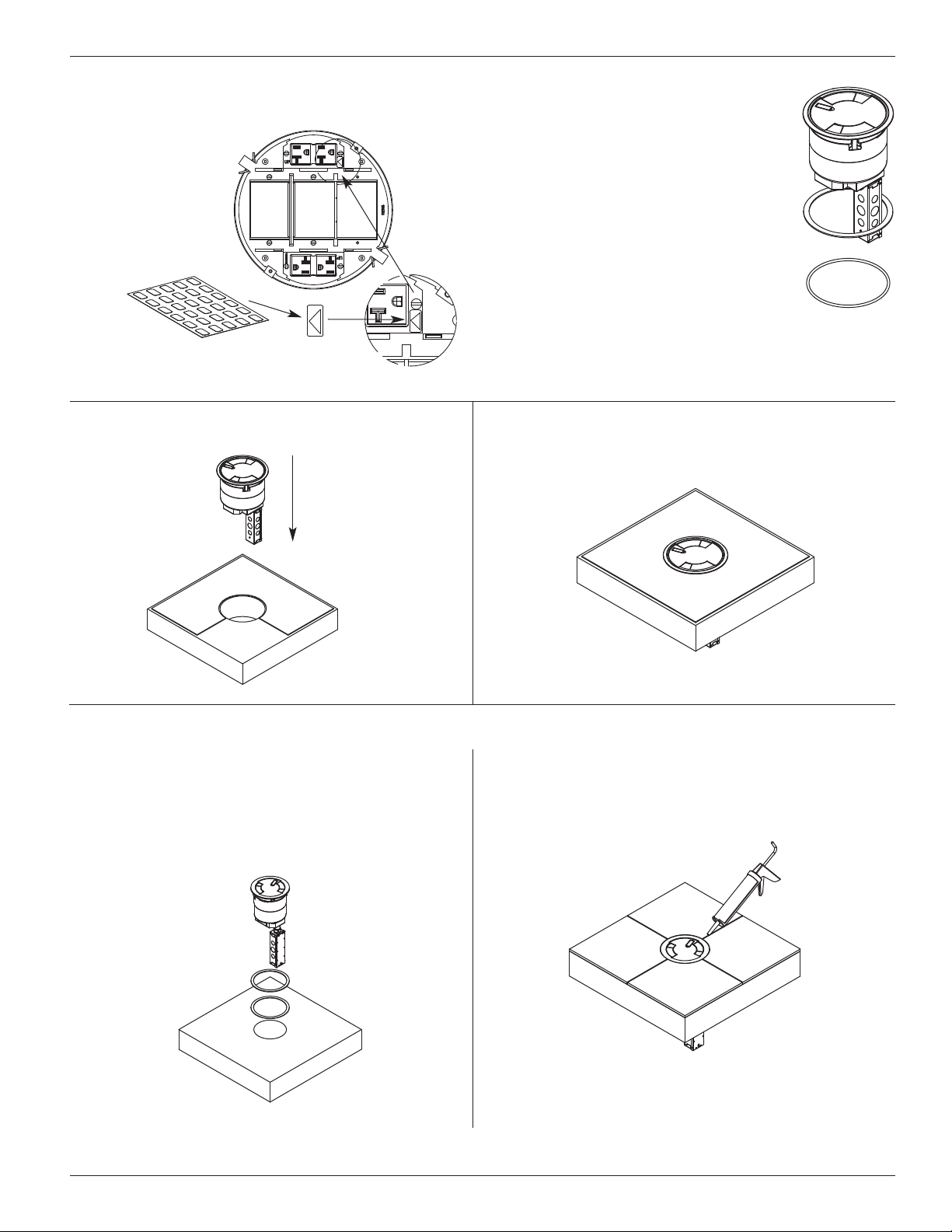
Step 2 If circuit is connected to an isolated
ground, apply IG icon on receptacle
plate as shown.
or Carpet or Surface Mounted Tile Installation
F
Step 3 Place appropriate gasket around
poke thru and slide under flange.
Use flat foam gasket for surface
ile applications or use round
t
neoprene gasket for carpet
applications. For the flush tile
applications no gasket is needed.
NOTE: The orange triangle shall only be placed
on devices that are wired for isolated
ground. See NEC 250-146(d).
Step 4 Push Poke-Thru into floor.
Step 5 Installation complete.
For Flush Tile Installation (Start with Steps 1 & 2 on previous page.)
Step 3 Place shims around bottom of flange to
Step 4 Use grout and/or silicone caulk
match thickness of tile. Flange is 1/8"
thick. (2) 1/8" shims and (2) 1/16" shims
are provided. Push Poke-Thru into floor.
between edges of flange and tile.
NOTE: If more shims are required, use Cat. No 8TS.
3
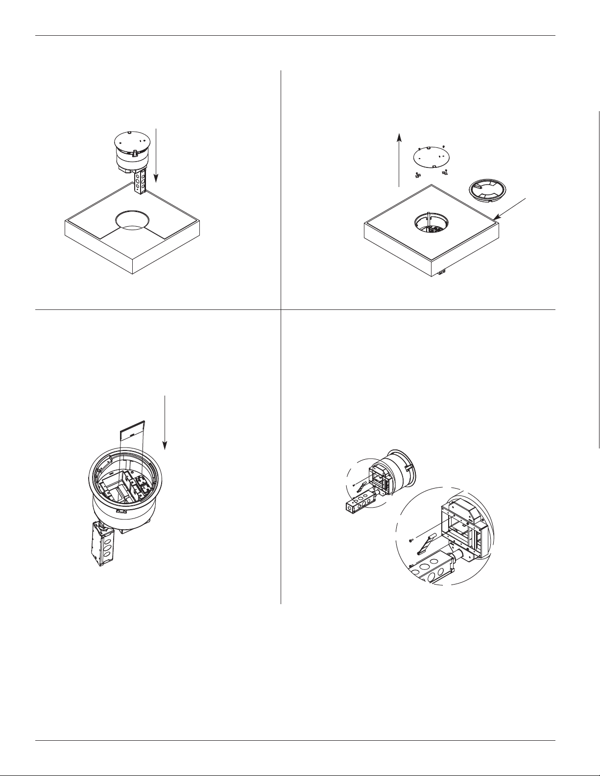
INSTALLING STEM ASSEMBLY AND SEPARATE COVER
Step 1 Insert Stem Assembly into core hole.
INSTALLING DIVIDERS
Step 1 Slide divider into slots in body of Poke
Thru. Two sets of slots are provided.
Either set may be used.
Step 2 Remove disposable plate and (2) plate clips by
removing the 8-32 screws. Install Flange using
the (2) 8-32 x 1/2” Cap Head screws provided
with the cover assembly.
Step 2 Two dividers are provided for the bottom of
the Poke Thru. Use the shorter divider on top
of Wire Tunnel. Use the longer divider when
separating channels without the Wire Tunnel.
To install, turn divider at an angle to place
inside the Feed Housing. Once inside, twist the
divider to align with holes in the Feed Housing.
Attach using (2) # 8-32 screws.
4
 Loading...