


UPS

UPS user manual
Manuel de l’utilisateur de l’ASI
Utilizzo dell’UPS
Rev.
Descrizione
Description
Data
Date
Emesso
Issued
Approvato
Approved
Lingua
Language
Pagina
Page
di Pag.
of Pag.
B VR 31-17 17.02.17 R. Soldani G. Senesi
E/I 1 164
Codice / Code
OMG38225
UPS USER MANUAL
MANUEL DE L’UTILISATEUR DE L’ASI
UTILIZZO DELL’UPS
Index / Indice
ENGLISH LANGUAGE ................................................................................... 9
1 SCOPE ................................................................................................... 11
2 SAFETY RULES AND WARNINGS ....................................................... 12
3 GENERAL UPS DESCRIPTION ............................................................. 13
3.1 TYPOLOGY ..................................................................................................................... 13
3.2 SYSTEM DESCRIPTION ................................................................................................. 13
3.2.1 Rectifier ................................................................................................................... 13
3.2.2 Inverter .................................................................................................................... 14
3.2.3 Battery and battery charger ................................................................................... 14
3.2.4 Static bypass ........................................................................................................... 14
3.2.5 Manual bypass ........................................................................................................ 14
3.3 OPERATING STATUS ..................................................................................................... 15
3.3.1 Normal operation .................................................................................................... 15
3.3.2 Green Conversion ................................................................................................... 15
3.3.3 Bypass operation .................................................................................................... 16
3.3.4 Battery operation .................................................................................................... 16
3.3.5 Manual bypass ........................................................................................................ 17

UPS user manual
Manuel de l’utilisateur de l’ASI
Utilizzo dell’UPS
2 OMG38225 REV. B
3.4 CONTROL AND OPERATION DEVICES ........................................................................ 19
3.4.1 Isolators .................................................................................................................. 19
3.4.2 Emergency power off command (EPO) ................................................................. 20
3.4.3 Normal/Bypass selector ......................................................................................... 20
3.4.4 LCD control panel ................................................................................................... 20
4 FRONT PANEL ....................................................................................... 21
4.1 FUNCTION BUTTONS .................................................................................................... 22
4.2 MIMIC PANEL LED’S ...................................................................................................... 23
4.3 LED’S BAR ...................................................................................................................... 24
5 HANDLING THE LCD PANEL ................................................................ 25
5.1 MAIN MENUS .................................................................................................................. 25
5.2 MEASURE DISPLAY ....................................................................................................... 26
5.3 BASIC DIAGNOSTICS .................................................................................................... 28
5.3.1 Display of alarms history ....................................................................................... 29
5.3.2 Alarms and operating status ................................................................................. 30
6 SETTINGS AND ADVANCED OPERATIONS ........................................ 32
6.1 SETTING DATE AND TIME ............................................................................................. 34
6.2 DISPLAY LANGUAGE SETTING .................................................................................... 34
6.3 NEW BATTERY INSTALLATION .................................................................................... 34
6.4 BATTERY CONFIGURATION ......................................................................................... 34
6.5 SETTING THE MODBUS PARAMETERS ....................................................................... 36
6.6 UPS TEST ....................................................................................................................... 36
6.7 BATTERY TEST .............................................................................................................. 37
6.8 SYSTEM RESET ............................................................................................................. 37
6.9 ALARMS HISTORY RESET ............................................................................................ 38
7 SYSTEM INFORMATION........................................................................ 39
7.1 PARALLEL OPERATION INFORMATION ...................................................................... 40
7.1.1 UPS position ........................................................................................................... 40
7.1.2 Master / Slave priority ............................................................................................ 40
7.1.3 Communication bus monitoring ............................................................................ 41
7.1.4 Parallel type ............................................................................................................ 41
7.1.5 Message statistics .................................................................................................. 43
7.2 SERVICE INFORMATION ............................................................................................... 43
8 FAULTS AND ALARMS ......................................................................... 44

UPS user manual
Manuel de l’utilisateur de l’ASI
Utilizzo dell’UPS
OMG38225 REV.B
3
8.1 OPERATING STATUS DEFINITION ................................................................................ 45
8.2 TROUBLESHOOTING ..................................................................................................... 47
LANGUE FRANÇAIS .................................................................................... 60
1 PORTEE ................................................................................................. 62
2 REGLES DE SECURITE ET AVERTISSEMENTS ................................. 62
3 DESCRIPTION GÉNÉRALE DE L'ASI ................................................... 63
3.1
TYPOLOGIE .................................................................................................................... 63
3.2
DESCRIPTION DU SYSTÈME ......................................................................................... 63
3.2.1 Redresseur .............................................................................................................. 63
3.2.2 Onduleur .................................................................................................................. 64
3.2.3 Batterie et chargeur de batterie ............................................................................. 64
3.2.4 By-pass statique ..................................................................................................... 64
3.2.5 Bypass manuel ........................................................................................................ 64
3.3
ÉTAT DE FONCTIONNEMENT ........................................................................................ 65
3.3.1 Fonctionnement normal ......................................................................................... 65
3.3.2 Conversion Green ................................................................................................... 65
3.3.3 Fonctionnement en by-pass ................................................................................... 66
3.3.4 Fonctionnement sur batterie .................................................................................. 67
3.3.5 Bypass manuel ........................................................................................................ 68
3.4
DISPOSITIFS DE CONTROLE ET DE FONCTIONNEMENT ........................................... 70
3.4.1 Sectionneurs d'isolation ......................................................................................... 70
3.4.2 Bouton d'arrêt d'urgence (EPO) ............................................................................. 71
3.4.3 Sélecteur normal/by-pass ....................................................................................... 71
3.4.4 Panneau de commande LCD .................................................................................. 71
4 PANNEAU AVANT ................................................................................. 72
4.1
TOUCHES DE FONCTION ............................................................................................... 73
4.2
FONCTION DES LED DU TABLEAU A SCHEMA ........................................................... 74
4.3
PANNEAU A LED ............................................................................................................ 75
5 MANIPULATION DU PANNEAU LCD.................................................... 76
5.1
MENUS PRINCIPAUX ...................................................................................................... 76
5.2
AFFICHAGE DES MESURES .......................................................................................... 77
5.3
DIAGNOSTICS DE BASE ................................................................................................ 79
5.3.1 Affichage de l'historique des alarmes ................................................................... 80

UPS user manual
Manuel de l’utilisateur de l’ASI
Utilizzo dell’UPS
4 OMG38225 REV. B
5.3.2 Alarmes et états de fonctionnement ALARMES ................................................... 81
6 REGLAGES ET OPERATIONS AVANCEES .......................................... 83
6.1
REGLAGE DE LA DATE ET DE L'HEURE ..................................................................... 85
6.2
AFFICHAGE DES LANGUES DISPONIBLES ................................................................. 85
6.3
INSTALLATION D'UNE NOUVELLE BATTERIE ............................................................ 85
6.4
CONFIGURATION DE LA BATTERIE ............................................................................. 85
6.5
REGLAGE DES PARAMETRES MODBUS ..................................................................... 87
6.6
TEST DE L’ASI ................................................................................................................ 87
6.7
TEST DE LA BATTERIE.................................................................................................. 88
6.8
RÉINITIALISATION DU SYSTÈME ................................................................................. 88
6.9
REMISE A ZERO DE L'HISTORIQUE DES ALARMES ................................................... 90
7 INFORMATIONS SYSTÈME ................................................................... 91
7.1
INFORMATIONS SUR LE FONCTIONNEMENT EN PARALLELE ................................. 92
7.1.1 Position de l’ASI ..................................................................................................... 92
7.1.2 Hiérarchie maitre / esclave ..................................................................................... 92
7.1.3 Surveillance du bus de communication ................................................................ 93
7.1.4 Type de système parallèle ..................................................................................... 93
7.1.5 Statistiques relatives aux messages ..................................................................... 93
8.4 INFORMATIONS RELATIVES À L'ENTRETIEN ............................................................. 94
8 DEFAUTS ET ALARMES ....................................................................... 95
8.1
DEFINITION DES ETATS DE FONCTIONNEMENT ........................................................ 96
8.2
DEPANNAGE .................................................................................................................. 98
LINGUA ITALIANA ...................................................................................... 111
1 APPLICABILITÀ ................................................................................... 113
2 REGOLE E AVVERTENZE DI SICUREZZA ......................................... 114
3 DESCRIZIONE GENERALE DELL’UPS ............................................... 115
3.1 TIPOLOGIA ................................................................................................................... 115
3.2 DESCRIZIONE DEL SISTEMA ...................................................................................... 115
3.2.1 Raddrizzatore ........................................................................................................ 115
3.2.2 Inverter .................................................................................................................. 116
3.2.3 Batteria e carica batteria ...................................................................................... 116
3.2.4 Bypass statico ...................................................................................................... 116
3.2.5 Bypass manuale ................................................................................................... 116

UPS user manual
Manuel de l’utilisateur de l’ASI
Utilizzo dell’UPS
OMG38225 REV.B
5
3.3 STATI DI FUNZIONAMENTO ........................................................................................ 117
3.3.1 Funzionamento normale ....................................................................................... 117
3.3.2 Green Conversion ................................................................................................. 117
3.3.3 Funzionamento da bypass ................................................................................... 118
3.3.4 Funzionamento da batteria .................................................................................. 118
3.3.5 Bypass manuale ................................................................................................... 119
3.4 COMANDI E ORGANI DI MANOVRA ............................................................................ 121
3.4.1 Sezionatori ............................................................................................................ 121
3.4.2 Comando di arresto di emergenza (EPO) ............................................................ 122
3.4.3 Selettore Normale/Bypass .................................................................................... 122
3.4.4 Pannello di comando LCD .................................................................................... 122
4 PANNELLO FRONTALE ...................................................................... 123
4.1 TASTI FUNZIONE .......................................................................................................... 124
4.2 LED DEL SINOTTICO .................................................................................................... 125
4.3 BARRA LED .................................................................................................................. 126
5 GESTIONE DEL PANNELLO LCD ...................................................... 127
5.1 MENU PRINCIPALI ........................................................................................................ 127
5.2 VISUALIZZAZIONE DELLE MISURE ............................................................................ 128
5.3 DIAGNOSTICA DI BASE ............................................................................................... 130
5.3.1 Visualizzazione dello storico allarmi ................................................................... 131
5.3.2 Lista degli allarmi e degli stati ............................................................................. 132
6 IMPOSTAZIONI E OPERAZIONI AVANZATE ..................................... 134
6.1 IMPOSTAZIONE DI DATA E ORA ................................................................................. 136
6.2 IMPOSTAZIONE LINGUA DISPLAY ............................................................................. 136
6.3 INSTALLAZIONE NUOVA BATTERIA .......................................................................... 136
6.4 CONFIGURAZIONE BATTERIA .................................................................................... 136
6.5 IMPOSTAZIONE PARAMETRI MODBUS ...................................................................... 138
6.6 TEST DELL’UPS ............................................................................................................ 138
6.7 TEST DI BATTERIA ....................................................................................................... 139
6.8 RESET DEL SISTEMA ................................................................................................... 139
6.9 RESET STORICO ALLARMI ......................................................................................... 141
7 INFORMAZIONI SUL SISTEMA ........................................................... 142
7.1 INFORMAZIONI SUL FUNZIONAMENTO IN PARALLELO .......................................... 143
7.1.1 Posizione dell’UPS ................................................................................................ 143

UPS user manual
Manuel de l’utilisateur de l’ASI
Utilizzo dell’UPS
6 OMG38225 REV. B
7.1.2 Priorità Master / Slave .......................................................................................... 143
7.1.3 Controllo bus di comunicazione ......................................................................... 144
7.1.4 Tipo di parallelo .................................................................................................... 144
7.1.5 Statistiche messaggi ............................................................................................ 146
7.2 INFORMAZIONI RELATIVE ALL’ASSISTENZA ........................................................... 146
8 GUASTI E ALLARMI ............................................................................ 147
8.1 DEFINIZIONE DEGLI STATI DI FUNZIONAMENTO ..................................................... 148
8.2 CONTROLLO DEI GUASTI ........................................................................................... 150

UPS user manual
Manuel de l’utilisateur de l’ASI
Utilizzo dell’UPS
OMG38225 REV.B
7
Index of pictures / Indice delle figure
Picture 1 – Block diagram ................................................................................................................................... 13
Picture 2 – Normal operation .............................................................................................................................. 15
Picture 3 – Green Conversion ............................................................................................................................. 15
Picture 4 – Load supplied by bypass .................................................................................................................. 16
Picture 5 – Battery operation ............................................................................................................................... 17
Picture 6 – Manual bypass for functional checks ................................................................................................ 17
Picture 7 – Manual bypass for repair or maintenance works .............................................................................. 18
Picture 8 – UPS front panel ................................................................................................................................. 21
Picture 9 – UPS mimic panel .............................................................................................................................. 23
Picture 10 – LED's bar ........................................................................................................................................ 24
Picture 11 – Structure of MEASURES menu (1 of 2) .......................................................................................... 26
Picture 12 – Structure of MEASURES menu (2 of 2) .......................................................................................... 27
Picture 13 – Structure of ALARMS menu............................................................................................................ 28
Picture 14 – Structure of SPECIAL menu ........................................................................................................... 32
Picture 15 – Structure of INFO menu .................................................................................................................. 39
Illustration 1 – Schéma bloc ................................................................................................................................ 63
Illustration 2 – Fonctionnement normal ............................................................................................................... 65
Illustration 3 – Green Conversion ....................................................................................................................... 65
Illustration 4 – Charge alimentée par bypass ...................................................................................................... 66
Illustration 5 – Fonctionnement sur batterie ........................................................................................................ 67
Illustration 6 – Bypass manuel pour vérification fonctionnelle ............................................................................ 68
Illustration 7 – By-pass manuel pour réparations ou maintenance ..................................................................... 69
Illustration 8 – Panneau avant de l’ASI ............................................................................................................... 72
Illustration 9 – Tableau à schéma de l’ASI .......................................................................................................... 74
Illustration 10 – Barre à led ................................................................................................................................. 75
Illustration 11 – Structure du menu MEASURES (mesures) (1 à 2) ................................................................... 77
Illustration 12 – Structure du menu MEASURES (mesures) (2 à 2) ................................................................... 78
Illustration 13 – Structure du menu ALARMS (ALARMES)................................................................................. 79
Illustration 14 – Structure du menu SPECIAL ..................................................................................................... 83
Illustration 15 – Structure du menu INFO............................................................................................................ 91
Figura 1 – Schema a blocchi ............................................................................................................................. 115
Figura 2 – Funzionamento normale .................................................................................................................. 117
Figura 3 – Green Conversion ............................................................................................................................ 117
Figura 4 – Carico alimentato da bypass............................................................................................................ 118

UPS user manual
Manuel de l’utilisateur de l’ASI
Utilizzo dell’UPS
8 OMG38225 REV. B
Figura 5 – Funzionamento da batteria .............................................................................................................. 119
Figura 6 – Bypass manuale per prove funzionali .............................................................................................. 119
Figura 7 – By-pass manuale per manutenzione o riparazione ......................................................................... 120
Figura 8 – Pannello frontale UPS ..................................................................................................................... 123
Figura 9 – Sinottico UPS ................................................................................................................................... 125
Figura 10 – Barra LED ...................................................................................................................................... 126
Figura 11 – Struttura menu MISURE (1 di 2) .................................................................................................... 128
Figura 12 – Struttura menu MISURE (2 di 2) .................................................................................................... 129
Figura 13 – Struttura menu allarmi ................................................................................................................... 130
Figura 14 – Struttura menu SPECIALE ............................................................................................................ 134
Figura 15 – Struttura menu INFO ..................................................................................................................... 142

UPS user manual
Manuel de l’utilisateur de l’ASI
Utilizzo dell’UPS
OMG38225 REV.B
9
ENGLISH LANGUAGE

UPS user manual
Manuel de l’utilisateur de l’ASI
Utilizzo dell’UPS
10 OMG38225 REV. B

UPS user manual
Manuel de l’utilisateur de l’ASI
Utilizzo dell’UPS
OMG38225 REV.B
11
1 SCOPE
The instructions contained in the operating manual are applicable to the UPS systems listed
below.
BSL46 KEOR HPE 60 kVA
BSM46 KEOR HPE 80 kVA
BSK93 KEOR HPE 100 kVA
BSM47 KEOR HPE 125 kVA
BSM10 KEOR HPE 160 kVA
Storing documentation
This manual and any other supporting technical documentation relating to the product
must be stored and made accessible to personnel in the immediate vicinity of the
UPS.
Further information
In the event that the information provided in this manual is not sufficiently exhaustive,
please contact the manufacturer of the device, whose details are available in the
“Contacts” section.
UPS user manual
Manuel de l’utilisateur de l’ASI
Utilizzo dell’UPS
12 OMG38225 REV. B
2 SAFETY RULES AND WARNINGS
Injury hazard due to electric shock!
Always respect all the safety instructions and, in particular:
any work on the unit must be carried out by qualified personnel;
internal components can only be accessed after disconnecting the device from
supply sources;
always use protective devices designed for each type of activity;
the instructions contained in the manuals must be strictly followed.
Injury hazard due to device failure
Potentially hazardous situations may arise in case of UPS failure.
Do not use the device if visibly damaged.
Maintain the device regularly to identify possible failure.
Possible device damage
Whenever work is carried out on the device, make sure all actions are taken in order
to avoid electrostatic discharges which might damage the electronic components of
the system.
Read the technical documentation
Before installing and using the device, make sure you have read and understood all
the instructions contained in the present manual and in the technical supporting
documentation.
UPS user manual
Manuel de l’utilisateur de l’ASI
Utilizzo dell’UPS
OMG38225 REV.B
13
3 GENERAL UPS DESCRIPTION
3.1 TYPOLOGY
The UPS described in this manual is on-line, double conversion; the inverter included in the UPS
always supplies energy to the load, whether mains is available or not (according to the battery
autonomy time).
This configuration guarantees the best service to the User, as it supplies clean power
uninterruptedly, ensuring voltage and frequency stabilization at nominal value. Thanks to the double
conversion, it makes the load completely immune from micro-interruptions and from excessive mains
variations, and prevents damage to critical loads (Computer - Instrumentation - Scientific equipment
etc.).
Output voltage present
The line connected to the UPS output is energized even during mains failure,
therefore in compliance with the prescriptions of IEC EN62040-1, the installer will
have to identify the line or the plugs supplied by the UPS making the User aware of
this fact.
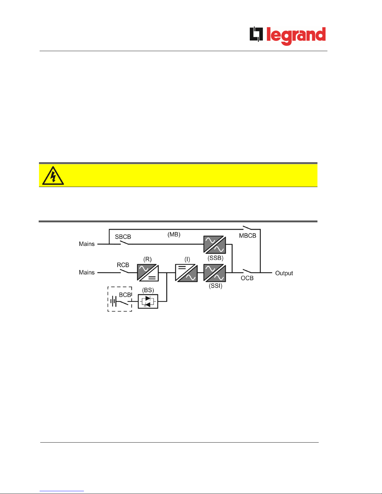
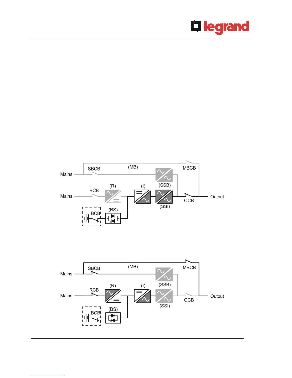
Picture 1 – Block diagram
The UPS uses IGBT technology with a high switching frequency in order to allow a low distortion
of the current re-injected into the supply line, as well as high quality and stability of output voltage.
The components used assure high reliability, very high efficiency and maintenance easiness.
3.2 SYSTEM DESCRIPTION
3.2.1 Rectifier
It converts the three-phase voltage of the AC mains into continuous DC voltage.
It uses a three-phase fully-controlled IGBT bridge with a low harmonic absorption.
The control electronics uses a 32 bit µP of latest generation that allows to reduce the distortion of
the current absorbed by mains (THDi) to less than 3%. This ensures that the rectifier does not
distort the supply mains, with regard to the other loads. It also avoids cable overheating due to the
harmonics circulation.
The rectifier is so sized as to supply the inverter at full load and the battery at the maximum
charging current.

UPS user manual
Manuel de l’utilisateur de l’ASI
Utilizzo dell’UPS
14 OMG38225 REV. B
3.2.2 Inverter
It converts the direct voltage coming from the rectifier or from the DC battery into alternating AC
voltage stabilized in amplitude and frequency.
The inverter uses IGBT technology with a high switching frequency of approximately 8 kHz.
The control electronics uses a 32 Bit µP of latest generation that, thanks to its processing
capability, generates an excellent output sine-wave.
Moreover, the fully digital control of the output sine-wave allows to achieve high performances,
among which a very low voltage distortion even in presence of high-distorting loads.
3.2.3 Battery and battery charger
The battery is installed outside the UPS. It is generally housed in an external battery cabinet.
The battery charger logic is completely integrated in the rectifier’s control electronics.
The battery is charged, according to the DIN 41773 Standard, every time it has been partially or
completely discharged. When its full capacity is restored, it is disconnected from the DC bus by
means of a static switch, in order to save energy, reduce the stress due to the AC ripple thus
increasing the lifetime. This operating mode is called Green Conversion.
It is however periodically charged but the prevailing state is of complete rest.
3.2.4 Static bypass
The Static Bypass allows to transfer the load between Inverter and Emergency Mains, and viceversa, in a very short time, and uses SCR’s as power commutation elements.
3.2.5 Manual bypass
The Manual Bypass is used to cut off the UPS completely, supplying the load directly from the
input mains in case of maintenance or serious failure.
Follow the procedures contained in the manual
The sequence of manual bypass switching and return must be carried out with
respect to the procedure indicated in the installation and start-up section. The
manufacturer cannot accept responsibility for damages arising from incorrect
operation.
External manual bypass
In the UPS system the manual bypass isolator is optional and installed outside the
unit.
UPS user manual
Manuel de l’utilisateur de l’ASI
Utilizzo dell’UPS
OMG38225 REV.B
15
3.3 OPERATING STATUS
The UPS has five different operating modes, as described below:
Normal operation
Green Conversion
Bypass operation
Battery operation
Manual bypass
3.3.1 Normal operation
During normal operation all the circuit breakers/isolators are closed, except for MBCB
(maintenance bypass).
The rectifier is supplied by the AC three-phase input voltage which, on its turn, feeds the inverter
and compensates mains voltage as well as load variations, keeping the DC voltage constant. At the
same time, it provides to charge the battery. The inverter converts the DC voltage into an AC sinewave with stabilized voltage and frequency, and also supplies the load via its static switch SSI.
Picture 2 – Normal operation
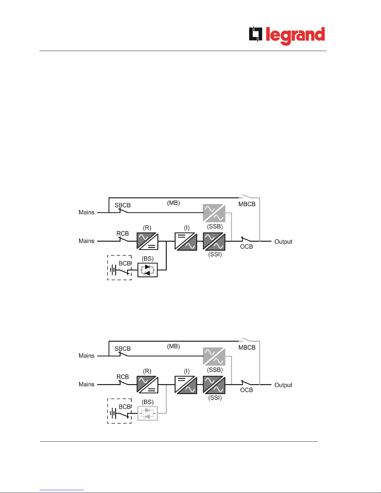
3.3.2 Green Conversion
During the operation in Green Conversion mode the battery is disconnected from the DC bus by
means of a static switch (see picture) and the rectifier works at reduced DC voltage; a control
algorithm provides to periodically re-connect the battery for recharge purposes (intermittent
charging).
Picture 3 – Green Conversion
UPS user manual
Manuel de l’utilisateur de l’ASI
Utilizzo dell’UPS
16 OMG38225 REV. B
When the Green Conversion algorithm is active the rectifier operates at reduced DC voltage and
supplies the inverter alone, since the battery is disconnected from the DC bus. The battery charge is
controlled by a specific algorithm. In case no mains outage events have occurred, and so no battery
discharges have occurred too, the control logic provides to start a charging cycle once every 25
days. The battery-charger restores the capacity lost due to the self-discharge and remains in floating
charge for additional 12 hours. As this time has elapsed the battery static switch is opened and the
battery is disconnected from the DC bus.
In case a discharge event occurs, the control logic provides to calculate the capacity which has
been lost during the discharge; as the mains is restored a charging cycle is started, which is
extended for an additional time that depends on the percentage of lost capacity, referred to the rated
value.
Lost capacity < 10% Additional charge for 12 hours
Lost capacity between 10% and 20% Additional charge for 48 hours
Lost capacity > 20% Additional charge for 96 hours
Such values complies with the recommendations of the main battery manufacturers.
Set the right battery capacity
The UPS front panel allows the setting of the battery parameters, including the rated
capacity. Considering the importance that such value assumes for the correct
execution of the charge control algorithm, it is highly recommended to verify the
correctness of the programmed value.
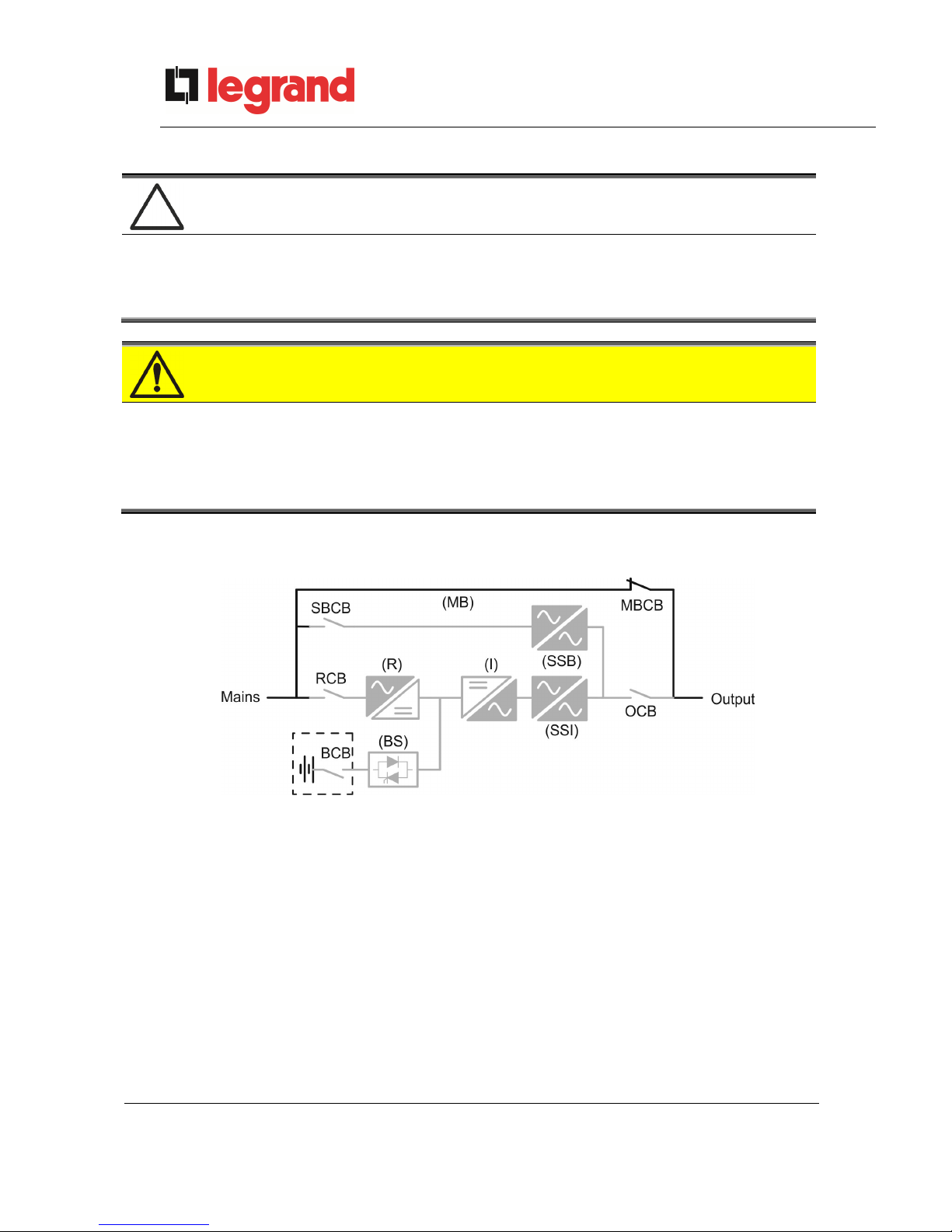
3.3.3 Bypass operation
The load can be switched to bypass either automatically or manually. The manual changeover is
due to the BYPASS SWITCH which forces the load to bypass. In case of failure of the bypass line,
the load is switched back to inverter without interruption.
Picture 4 – Load supplied by bypass
3.3.4 Battery operation
In case of power failure or rectifier fault, the battery feeds the inverter without interruption. The
battery voltage drops based on the amplitude of the discharging current. The voltage drop has no
effect on the output voltage, which is kept constant by changing the PWM modulation. An alarm is
activated when the battery is near the minimum discharge value.
UPS user manual
Manuel de l’utilisateur de l’ASI
Utilizzo dell’UPS
OMG38225 REV.B
17
In case the supply is restored before the battery is completely discharged, the system will be
switched back to normal operation automatically. In the opposite case, the inverter shuts down and
the load is switched to the bypass line (bypass operation). If the bypass line is not available or is out
of tolerance, the loads supply is interrupted as soon as the battery reaches the discharge limit
threshold (black-out).
As soon as the supply is restored, the rectifier will recharge the battery. In the standard
configuration, the loads are supplied again via static switch SSB when mains is available again. The
inverter is restarted when the battery has partially restored its capacity.
The system restart from the black-out condition can be customized based on the requirements of
the plant, in three different modes:
Bypass loads are supplied as soon as the bypass line is available (factory
configuration).
Inverter loads are supplied by the inverter (even if the bypass line is available)
when the battery voltage has reached a programmed threshold, after
the rectifier restart.
Man. Inverter the output supply is NOT restored automatically. The system requires a
confirmation to restart which can only be done manually by the user via
the front panel.
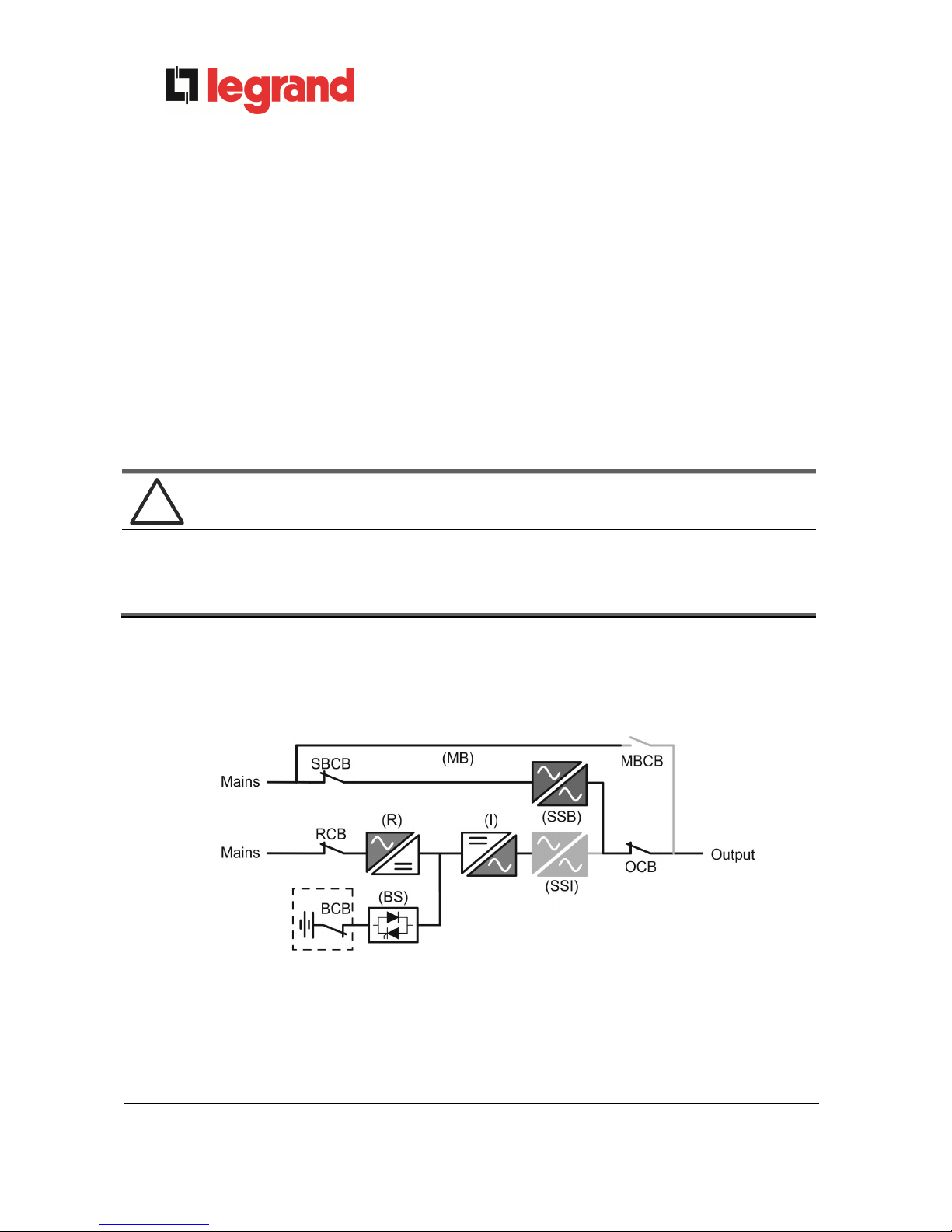
Picture 5 – Battery operation
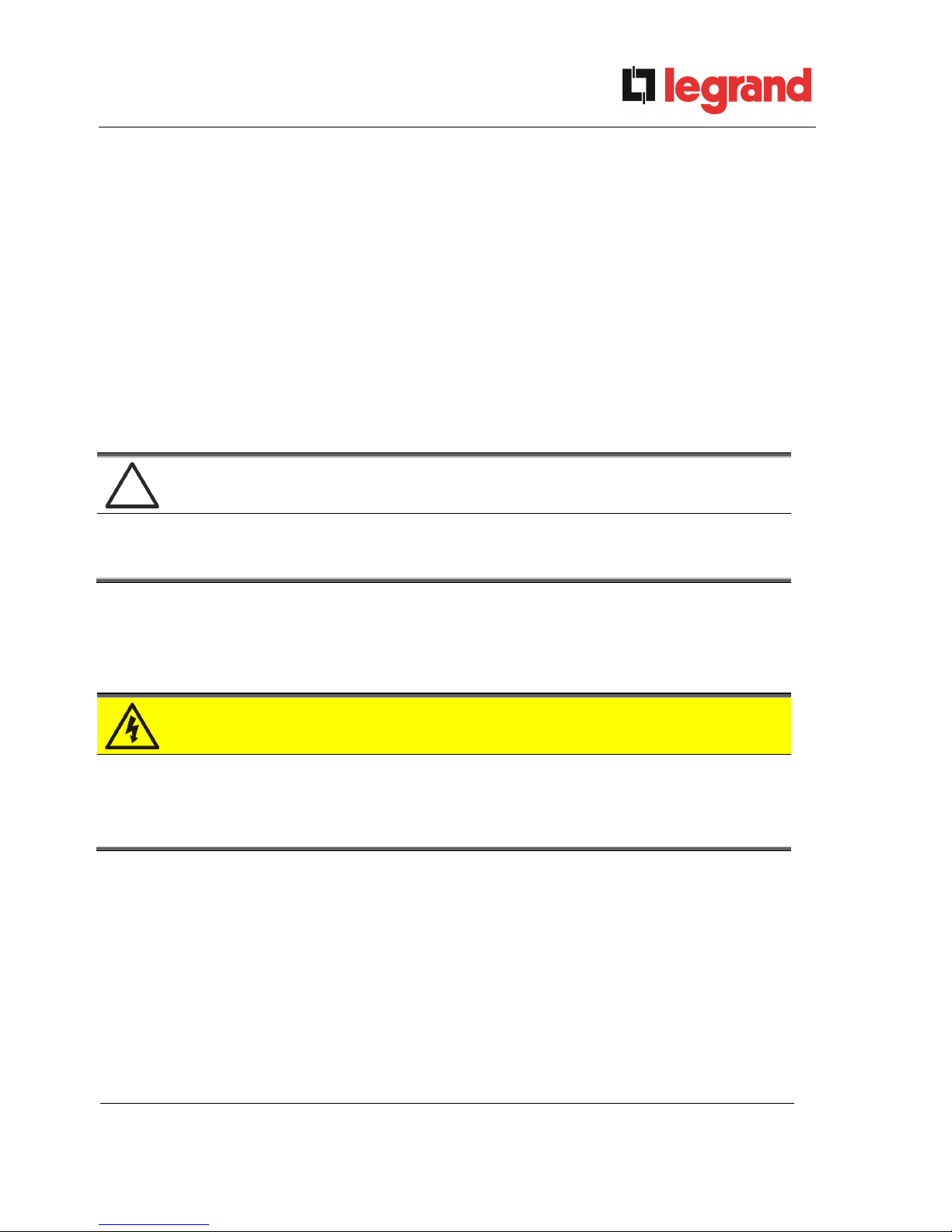
3.3.5 Manual bypass
The manual bypass operation is necessary whenever the UPS functionality is tested, or during
maintenance or repair work.
Picture 6 – Manual bypass for functional checks
UPS user manual
Manuel de l’utilisateur de l’ASI
Utilizzo dell’UPS
18 OMG38225 REV. B
Follow the procedures contained in the manual
The sequence of manual bypass switching and return must be carried out with
respect to the procedure indicated in the installation and start-up section. The
manufacturer cannot accept responsibility for damages arising from incorrect
operation.
Wiring of the auxiliary contacts
Carry out a proper electrical installation by wiring the auxiliary contacts of the manual
bypass and output isolators to the dedicated terminals on board the UPS. This will
allow the control logic to acquire the status of the switches and guide the operator
during the start-up and manual bypass procedures.
For further information refer to the section "Installation and start-up".
During the manual bypass due to repair or maintenance, the UPS is completely shut down and
the load is directly supplied by the bypass line.
Picture 7 – Manual bypass for repair or maintenance works
UPS user manual
Manuel de l’utilisateur de l’ASI
Utilizzo dell’UPS
OMG38225 REV.B
19
3.4 CONTROL AND OPERATION DEVICES
The control and operation devices of the UPS are indicated below:
Isolator on rectifier input (RCB)
Isolator on bypass input (SBCB)
Isolator on UPS output (OCB)
Manual bypass isolator (MBCB)
Battery Isolator / Circuit breaker (BCB) - External, inside the battery cabinet
Emergency power off button (EPO)
Normal/Bypass selector
LCD control panel
Check the personnel training
The use of the operation and control devices of the UPS is intended for authorized
personnel only. We recommend to check the training of the personnel responsible for
the use and maintenance of the system.
3.4.1 Isolators
The isolators provided on the UPS are used to isolate the power components of the device from
the AC supply line, from the storage battery and from the load.
Voltage present on terminals
The isolators do not isolate the UPS completely, since AC voltage is still present on
the UPS input terminals. Before carrying out any maintenance on the unit:
Isolate the device completely by operating the external circuit breakers;
Wait at least 5 minutes in order to allow the capacitors to discharge.
UPS user manual
Manuel de l’utilisateur de l’ASI
Utilizzo dell’UPS
20 OMG38225 REV. B
3.4.2 Emergency power off command (EPO)
The emergency power off command is used to disconnect the UPS output immediately,
interrupting the loads supply. It also shuts down the inverter.
Operate the command only in case of real emergency
The components of the system are subject to a high stress when the emergency
power off command is operated under load presence.
Use the emergency power off button only in case of real emergency.
Supply reset
Reset the output supply only when the causes which led to the emergency shutdown
have been eliminated and you are sure that there is no hazard to persons and things.
3.4.3 Normal/Bypass selector
The Normal/Bypass selector is installed externally, on the rear of UPS. It is generally used during
the manual bypass procedure, when it is necessary to isolate the UPS for maintenance or repair.
Follow the procedures contained in the manual
The Normal/Bypass selector shall only be operated in accordance with the
procedures specified in the installation and start-up section. The manufacturer cannot
accept responsibility for damages arising from incorrect operation.
3.4.4 LCD control panel
The control panel of the UPS is used in order to:
Check the operating parameters of the device
Check the alarms present
Access the event log
Display the information on the device
Modify the operating parameters
The menu which allows to change the parameters is password-protected in order to prevent
access to unauthorized personnel.
UPS user manual
Manuel de l’utilisateur de l’ASI
Utilizzo dell’UPS
OMG38225 REV.B
21
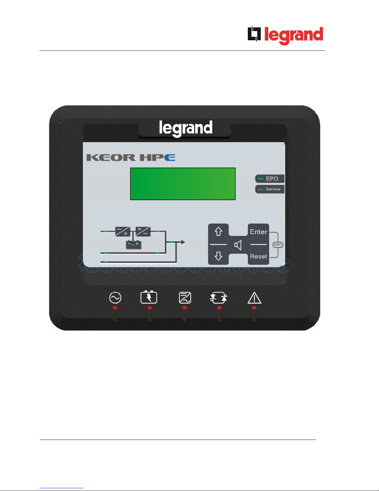
4 FRONT PANEL
The front panel of the UPS, consisting of four rows alphanumeric display plus 5 function keys,
allows the complete monitoring of the UPS status.
The mimic flow helps to understand the operating status of the UPS.
Picture 8 – UPS front panel

UPS user manual
Manuel de l’utilisateur de l’ASI
Utilizzo dell’UPS
22 OMG38225 REV. B
4.1 FUNCTION BUTTONS
The front panel of the UPS is provided with 5 buttons whose functions are indicated in the
following table:
Button
Assigned functions
Scrolls up the menus
Increases the values by one unit
Selects a value
Scrolls down the menus
Decreases the values by one unit
Selects a value
Selects a menu
Confirms changes
Silences the buzzer (activated due to an alarm or a failure)
Returns to the previous menu
UPS user manual
Manuel de l’utilisateur de l’ASI
Utilizzo dell’UPS
OMG38225 REV.B
23
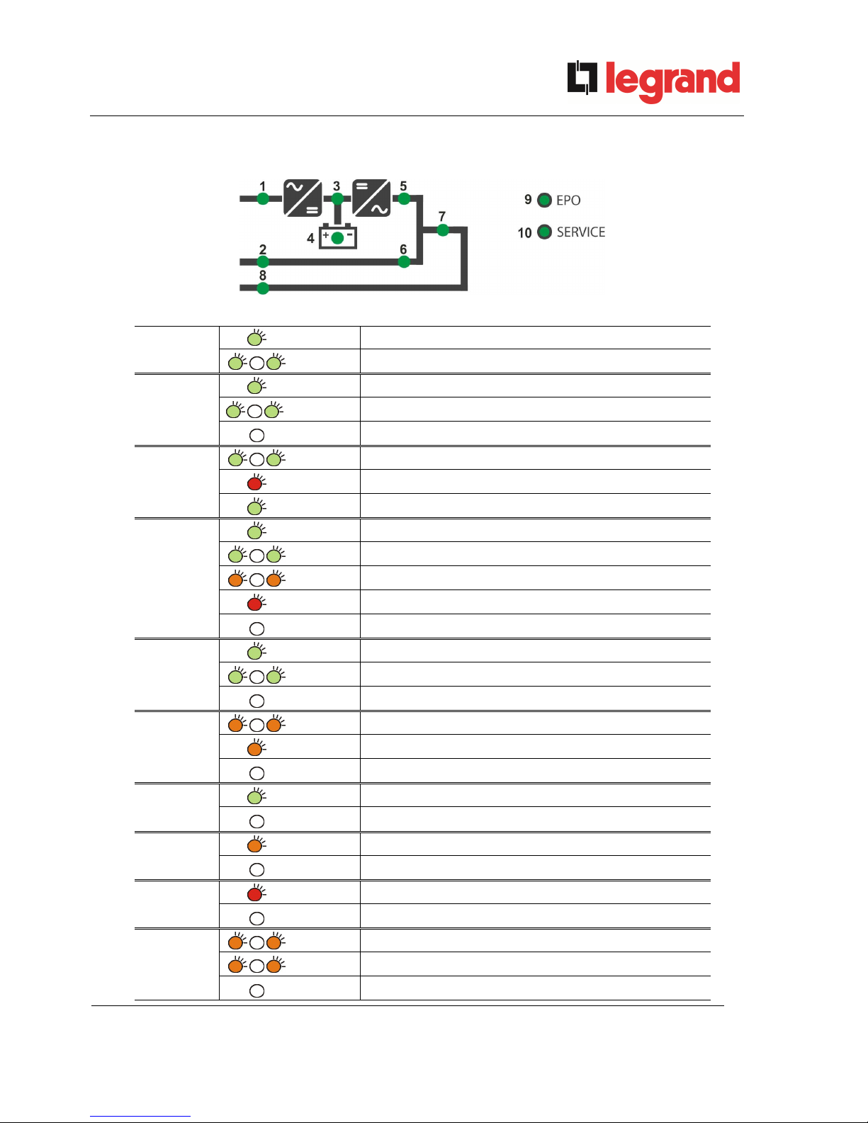
4.2 MIMIC PANEL LED’S
Picture 9 – UPS mimic panel
LED 1
GREEN
AC line on rectifier input within tolerance
GREEN
AC mains failure / Wrong phase rotation
LED 2
GREEN
AC bypass line within tolerance
GREEN
Wrong phase rotation
OFF
AC bypass line out of tolerance / failure
LED 3
GREEN
Rectifier off or faulty
RED
DC voltage out of tolerance
GREEN
Rectifier on and DC voltage within tolerance
LED 4
GREEN
Circuit breaker BCB closed and battery charging
GREEN
Battery discharging or under TEST
ORANGE
Circuit breaker BCB open
RED
Battery fault (following a battery test)
OFF
Battery not available
LED 5
GREEN
Inverter voltage within tolerance and static switch closed
GREEN
Inverter overload or short-circuit
OFF
Inverter off or voltage out of tolerance
LED 6
ORANGE
Re-transfer blocked
ORANGE
Static bypass switch closed
OFF
Static bypass switch open
LED 7
GREEN
Output circuit breaker OCB closed
OFF
Output circuit breaker OCB open
LED 8
ORANGE
Manual bypass switch MBCB closed
OFF
Manual bypass switch MBCB open
LED 9
RED
Emergency power off (EPO) activated
OFF
Normal operation
LED 10
ORANGE
Maintenance request (slow blinking)
ORANGE
Critical alarm (fast blinking)
OFF
Normal operation
UPS user manual
Manuel de l’utilisateur de l’ASI
Utilizzo dell’UPS
24 OMG38225 REV. B
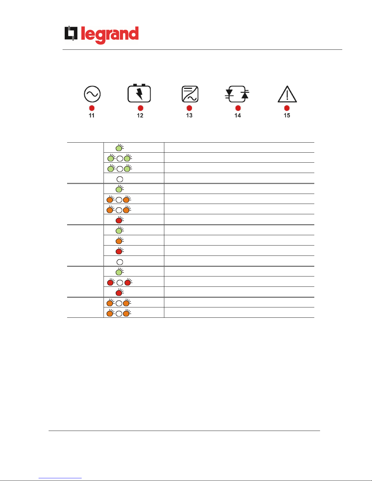
4.3 LED’S BAR
Picture 10 – LED's bar
LED 11
GREEN
AC line on rectifier input within tolerance
GREEN
Wrong phase rotation (fast blinking)
GREEN
Unbalanced AC voltage (slow blinking)
OFF
AC mains failure
LED 12
GREEN
Circuit breaker BCB closed and battery charging
ORANGE
Battery discharging or under TEST (fast blinking)
ORANGE
Circuit breaker BCB open (slow blinking)
RED
End of battery autonomy / Battery fault
LED 13
GREEN
Inverter voltage within tolerance and static switch closed
ORANGE
Inverter overload or short-circuit
RED
Inverter critical alarm
OFF
Inverter off
LED 14
GREEN
AC bypass line within tolerance
RED
Wrong phase rotation (fast blinking)
RED
AC bypass line out of tolerance / failure
LED 15
GREEN
Programmed maintenance required (slow blinking)
GREEN
Critical alarm (fast blinking)

UPS user manual
Manuel de l’utilisateur de l’ASI
Utilizzo dell’UPS
OMG38225 REV.B
25
5 HANDLING THE LCD PANEL
5.1 MAIN MENUS
UPS NAME
Main screen (nominal power of the UPS)
xxx kVA
UPS NAME
UPS measures regarding basic parameters
(voltage, current, etc.)
MEASURES
UPS NAME
UPS operating status, possible alarms present
and alarms history
ALARMS
UPS NAME
Setting of parameters and special functions
SPECIAL
UPS NAME
General information regarding the UPS
INFO
UPS user manual
Manuel de l’utilisateur de l’ASI
Utilizzo dell’UPS
26 OMG38225 REV. B
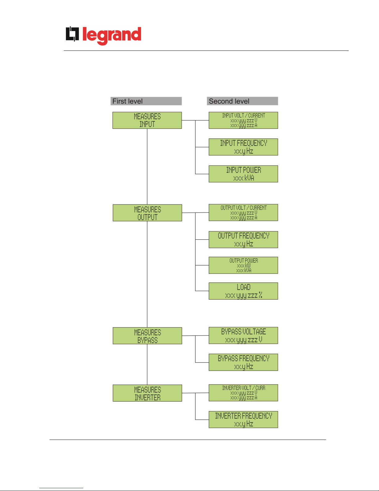
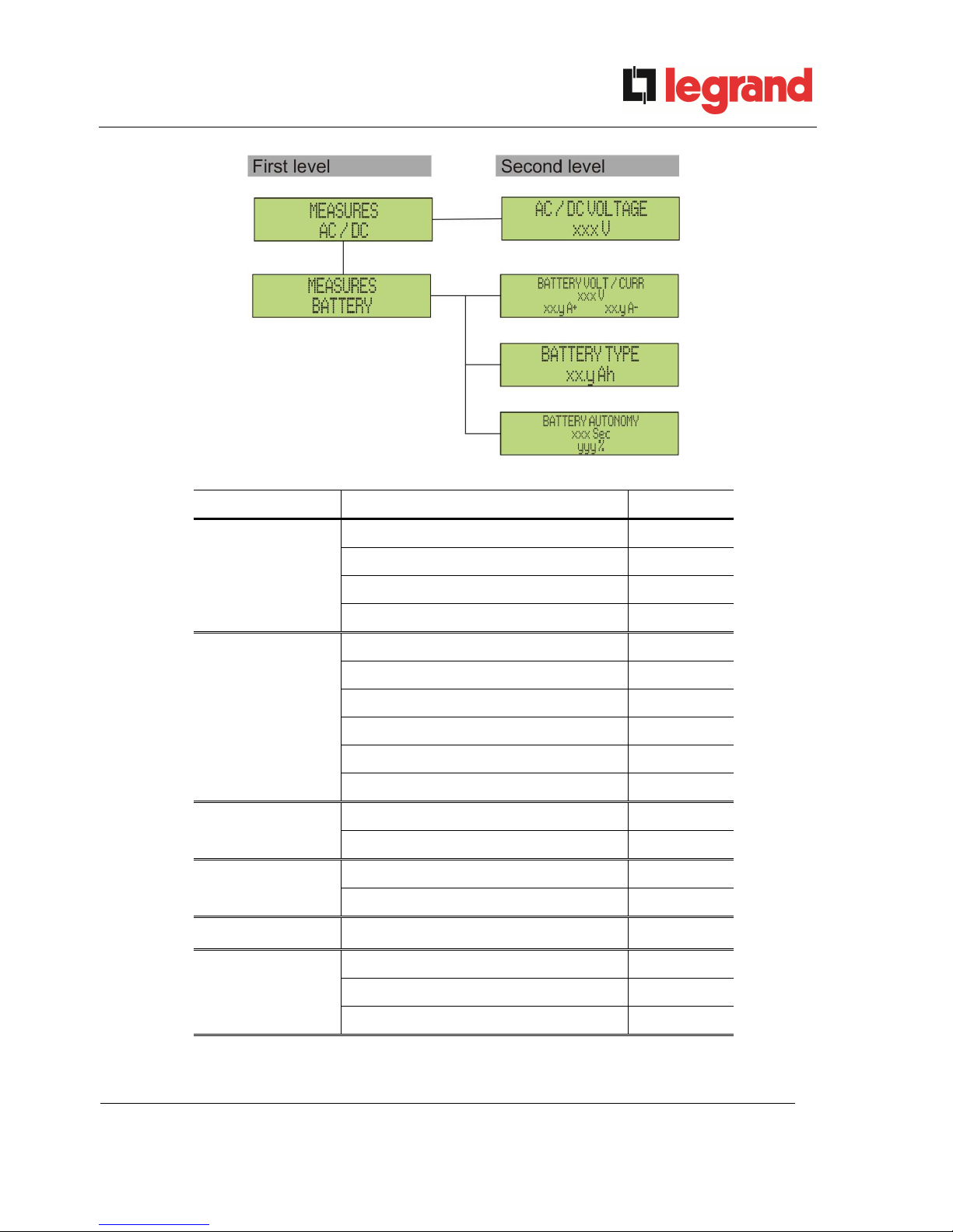
5.2 MEASURE DISPLAY
The MEASURES menu is structured as follows:
Picture 11 – Structure of MEASURES menu (1 of 2)
UPS user manual
Manuel de l’utilisateur de l’ASI
Utilizzo dell’UPS
OMG38225 REV.B
27
Picture 12 – Structure of MEASURES menu (2 of 2)
Sub-menu Displayed data Accuracy
INPUT
Rectifier input voltage
(1) (2)
1 V
Rectifier input current
(3)
1 A
Frequency 0.1 Hz
Input power 1 kVA
OUTPUT
Voltage
(1) (2)
1 V
Current
(3)
1 A
Frequency 0.1 Hz
Active power 1 kW
Apparent power 1 kVA
Load percentage 1 %
BYPASS
Voltage
(1) (2)
1 V
Frequency 0.1 Hz
INVERTER
Voltage
(1) (2)
1 V
Frequency 0.1 Hz
AC/DC
Rectifier output voltage 1 V
BATTERY
Voltage and current 1 V / 1 A
Nominal capacity 1 Ah
Residual autonomy 1 min / 1 %
(1)
The voltage measures are always referred to the phase-to-neutral value
(2)
The three voltages are displayed in one screen as “xxx yyy zzz V”
(3)
The three line currents are displayed in one screen as “xxx yyy zzz A”
UPS user manual
Manuel de l’utilisateur de l’ASI
Utilizzo dell’UPS
28 OMG38225 REV. B
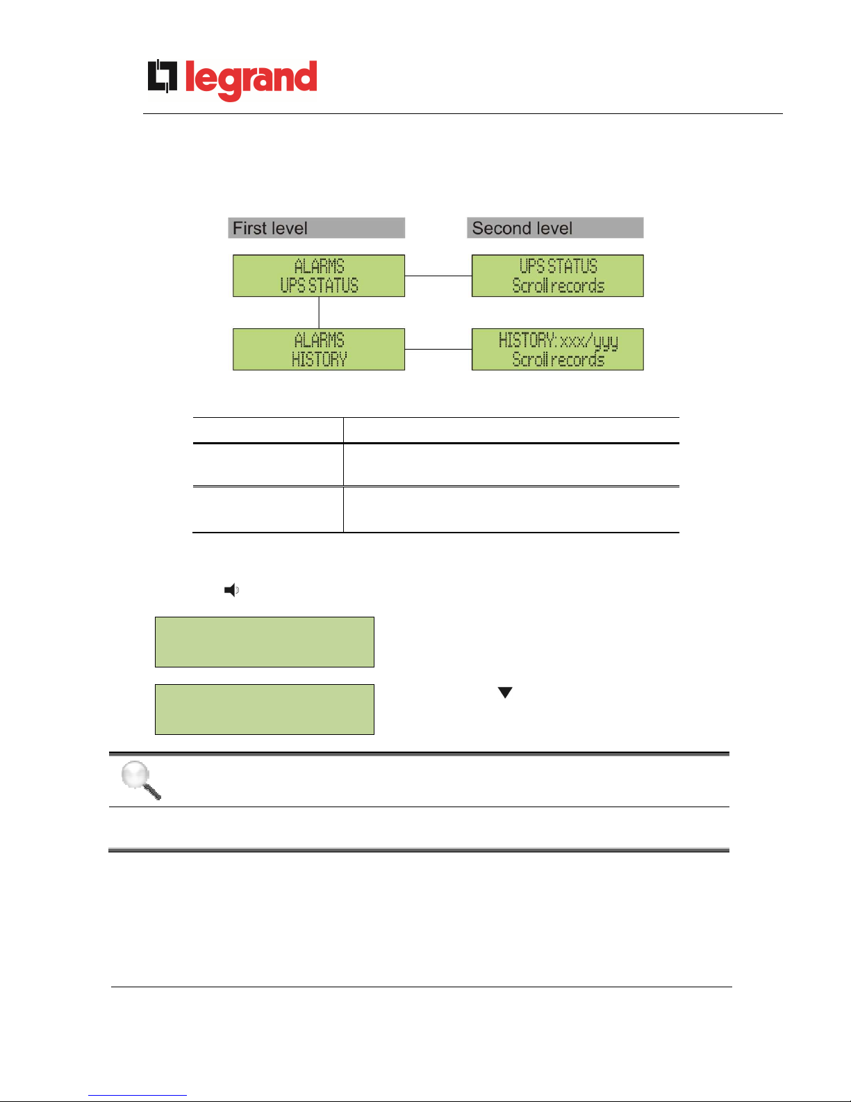
5.3 BASIC DIAGNOSTICS
The ALARMS menu allows to display the current operating status of the device and to access the
event log, based on the following structure.
Picture 13 – Structure of ALARMS menu
Sub-menu Displayed data
UPS STATUS
Alarms present and operating statuses
HISTORY
Event log
The LCD panel displays the ALARMS menu automatically whenever an alarm occurs. The
audible indicator, if enabled, is activated to show the occurred failure. The audible alarm is silenced
pressing the key (BUZZER).
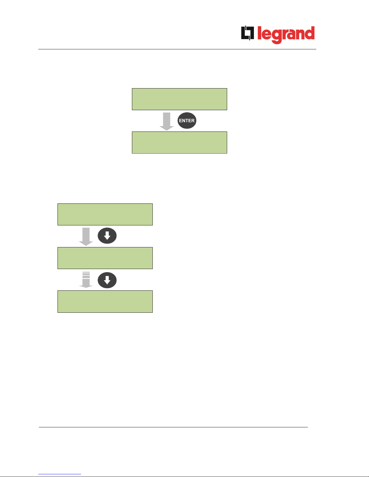
UPS STATUS
Display of the first alarm present (if no alarm is
present, the operating status is displayed)
alarm/status no. 1
UPS STATUS
Press the key to browse the menu and to go
to the next alarm/status (in alphabetical order)
Last alarm/status
Automatic erasure of alarms
Should an alarm occur and then the conditions that originated it no longer exist, the
alarm will be automatically cancelled and the system restarted.
UPS user manual
Manuel de l’utilisateur de l’ASI
Utilizzo dell’UPS
OMG38225 REV.B
29
5.3.1 Display of alarms history
All the events are recorded in the alarms history.
UPS STATUS
HISTORY
HISTORY: xxx/yyy
Alarm code Date/time
The first event shown is the latest one in order of time; a new event makes all the other events
automatically shift one position, clearing the oldest event.
The quantity of stored events is displayed on the first line (xxx/yyy), which contains the data
currently displayed (position in the list) and the total number of stored data (maximum number equal
to 500) respectively. An asterisk indicates the automatic reset of the alarm.
HISTORY: 001/015
Latest event stored (in order of time)
E.g.: automatic reset of alarm “A3 –
BOOSTER STOPPED”
A3 * 26-10-10 20:05
HISTORY: 002/015
Immediately prior event
E.g.: alarm “A3 – BOOSTER STOPPED”
A3 26-10-10 19:45
HISTORY: 015/015
First event stored (in order of time)
A18 15-10-10 12:49

UPS user manual
Manuel de l’utilisateur de l’ASI
Utilizzo dell’UPS
30 OMG38225 REV. B
5.3.2 Alarms and operating status
ALARMS
A1
MAINS FAULT
A28
CRITICAL FAULT
A2
INPUT WRONG SEQ
A29
MAINTENANCE REQ
A3
BOOSTER STOPPED
A30
COMMON ALARM
A4
BOOSTER FAULT
A31
MBCB BUS CLOSED
A5
DC VOLTAGE FAULT
A32
EPO BUS CLOSED
A6
BATTERY IN TEST
A33
ASYMMETRIC LOAD
A7
BCB OPEN
A34
SERVICE REQUIRED
A8
BATTERY DISCHARGE
A35
DIESEL MODE
A9
BATTERY AUT END
A36
DC FASTSHUTDOWN
A10
BATTERY FAULT
A38
INV --> LOAD
A11
SHORT CIRCUIT
A39
INV ERROR LOOP
A12
STOP TIMEOUT SC
A40
SSI FAULT
A13
INV OUT OF TOL
A41
RECT ERROR LOOP
A14
BYPASS WR SEQ
A
43
CURR ERROR LOOP
A15
BYPASS FAULT
A46
PAR LOST REDUND
A16
BYPASS --> LOAD
A45
HIGH TEMP SSW
A17
RETRANSFER BLOCK
A47
SEND PARAM ERROR
A18
MBCB CLOSED
A48
RCV PARAM ERROR
A19
OCB OPEN
A49
TEST MODE ERROR
A20
OVERLOAD
A50
SSW BLOCKED
A2
1
THERMAL IMAGE
A51
BATT TEMPERATURE
A22
BYPASS SWITCH
A52
INVERTER BLOCK
A23
EPO PRESSED
A53
FIRMWARE ERROR
A24
HIGH TEMPERATURE
A54
CAN ERROR
A25
INVERTER OFF
A55
PAR CABLE DISC
A26
COMMUNIC ERROR
A56
MAINS UNBALANCE
A27
EEPROM ERROR
A63
START SEQ BLOCK
 Loading...