


Selective Call Intercom
SYSTEM INSTALLATION GUIDE
1308003 REV.B
301 Fulling Mill Road, Suite G |
©Copyright 2008 by On-Q/Legrand, |
Middletown, PA 17057 |
Inc All Rights Reserved. |
(800)-321-2343 |
www.onqlegrand.com |
|
Page i |

Federal Communications Commission Statement
This device complies with Part 15 of the FCC Rules. Operation is subject to the following two conditions:
•Thisdevicemaynotcauseharmfulinterference,and
•Thisdevicemustacceptanyinterferencereceived,includinginterferencethatmaycauseundesiredoperation.
This equipment has been tested and found to comply with the limits for a class B digital device, pursuant to Part 15 of the Federal Communications Commission (FCC) rules. These limits are designed to provide reasonable protection against harmful interference in a residential installation. This equipment generates, uses, and can radiate radio frequency energy and, if not installed and used in accordance with the instructions, may cause harmful interference to radio communications. However, there is no guarantee that interference will not occur in a particular installation. If this equipment does cause harmful interference to radio or television reception, which can be determined by turning the equipment off and on, the user is encouraged to try to correct the interference by one or more of the following measures:
•Reorientorrelocatethereceivingantenna.
•Increasetheseparationbetweentheequipmentandreceiver.
•Connecttheequipmentintoanoutletonacircuitdifferentfromthattowhichthereceiverisconnected.
•Consultthedealeroranexperiencedradio/TVtechnicianforhelp.
Reprinted from the Code of Federal Regulations #47, part 15.193, 1993. Washington DC: Office of the Federal Register, National Archives and Records Administration, U.S. Government Printing Office.
WARNING: TO PREVENT FIRE OR SHOCK HAZARD, DO NOT EXPOSE THIS PRODUCT TO RAIN OR MOISTURE. THE UNIT MUST NOT BE EXPOSED TO DRIPPING OR SPLASHING WATER.
CAUTION: DO NOT OPEN THE UNIT. DO NOT PERFORM ANY SERVICING OTHER THAN THAT CONTAINED IN THE INSTALLATION AND TROUBLESHOOTING INSTRUCTIONS. REFER ALL SERVICING TO QUALIFIED SERVICE PERSONNEL.
CAUTION: THIS DEVICE MUST BE INSTALLED AND USED IN STRICT ACCORDANCE WITH THE MANUFACTURER’S INSTRUCTIONS AS DESCRIBED IN THE USER DOCUMENTATION THAT COMES WITH THE PRODUCT.
WARNING: POSTPONE INSTALLATION UNTIL THERE IS NO RISK OF THUNDERSTORM OR LIGHTNING ACTIVITY IN THE AREA.
When using this device, basic safety precautions should always be followed to reduce the risk of fire, electric shock and injury to persons, including the following:
•Read all of the instructions {listed here and/or in the user manual} before you operate this equipment.
•Give particular attention to all safety precautions.
•Retain the instructions for future reference.
•Comply with all warning and caution statements in the instructions.
•Observe all warning and caution symbols that are affixed to this equipment.
•Comply with all instructions that accompany this equipment.
•Avoid using this product during an electrical storm. There may be a risk of electric shock from lightning. It is recommended that the customer install an AC surge protector in the AC outlet to which this device is connected. This is to avoid damaging the equipment by local lightning strikes and other electrical surges.
•Operate this product only from the type of power source indicated on the product’s marking label.
•If you are not sure of the type of power supplied to your home, consult your dealer or local power company.
•Upon completion of any service or repairs to this product, ask the service technician to perform safety checks to determine that the product is in safe operating condition.
Installation of this product must be in accordance with national wiring codes and conform to local regulations.
Wipe the unit with a clean, dry cloth. Never use cleaning fluid or similar chemicals. Do not spray cleaners directly on the unit or use forced air to remove dust.
Keep the device away from excessive heat and humidity and keep the device free from vibration and dust.
301 Fulling Mill Road, Suite G |
©Copyright 2008 by On-Q/Legrand, |
Middletown, PA 17057 |
Inc All Rights Reserved. |
(800)-321-2343 |
www.onqlegrand.com |
Page ii

|
|
TABLE OF CONTENTS |
I. |
Introduction |
1 |
|
A. Installation Safety Precautions |
1 |
II. |
System Components Overview |
2 |
|
A. System Components |
2 |
III. Wiring Specifications |
3 |
|
|
A. Specifications |
3 |
|
B. Guidelines |
3 |
|
C. Unit Placement |
3 |
|
D. Termination Instructions |
3 |
IV. System Wiring Overview |
4 |
|
|
A. Pre-Wiring (Rough-In) |
4 |
|
B. Final Wiring (Trim-Out) |
7 |
V. System Configuration |
12 |
|
|
A. Choosing Unit Names |
12 |
|
B. Modifying Reply Options |
13 |
|
C. Room Options |
13 |
|
D. Door Options |
14 |
|
E. Patio Options |
15 |
|
F. Installer Setup |
15 |
VI. Troubleshooting |
20 |
|
|
A. Contact Information |
20 |
|
B. Troubleshooting Guide |
20 |
|
C. Warranty |
21 |
VII. Installer Checklist |
22 |
|
301 Fulling Mill Road, Suite G |
©Copyright 2008 by On-Q/Legrand, |
Middletown, PA 17057 |
Inc All Rights Reserved. |
(800)-321-2343 |
www.onqlegrand.com |
Page iii

301 Fulling Mill Road, Suite G |
©Copyright 2008 by On-Q/Legrand, |
Middletown, PA 17057 |
Inc All Rights Reserved. |
(800)-321-2343 |
www.onqlegrand.com |
Page iv

I. Installation Introduction
The On-Q/Legrand Selective Call Intercom System is an advanced Cat 5 based intercom system consisting of 2-gang Room Units, Patio Units and Door Units. Each of these user stations are connected with a single Cat 5 cable to an Intercom Module in the enclosure. The Room Units contain an intuitive graphical user interface in the form of a liquid crystal display, similar to today’s cell phones. Communication may occur in a broadcast fashion if desired, or to specific units as selected on the Room Unit LCD.
Installation of the system is simplistic due to the fact that all units are connected with a single Cat 5 cable and all units are the same small physical size. The firmware that runs on the system controller discovers each unit by type and keeps track of them. If a unit becomes disabled, it is removed from the system list and does not affect the other units. In fact, replacement is as simple as unplugging the old unit and plugging in the new unit, which will be automatically discovered and added to the list.
The robust system software allows you to install the system and utilize the defaults, for a quick and simple installation, or add value by customizing and personalizing the installation The system can be personalized, choosing what to call each user station from a list of over 90 names. The door tone can be personalized for each door unit, choosing from 20 different high quality door tones.
A. Installation Safety Precautions
NOTE: Read all instructions carefully and completely before installing the On-Q/Legrand Selective Call Intercom System.
Throughout the following safety precautions and instructions the term “component” will be used to indicate one or all of the following: Intercom Module, Room Unit, Patio Unit, or Door Unit.
•These installation instructions were designed for use by an authorized On-Q installer only. Do not attempt to service, move, or change any component of this system unless you are qualified to do so.
•This system must by installed to conform to all local building and electrical codes.
•Do not apply power to the Intercom Module until all Selective Call Intercom System components have been installed and all wiring has been properly terminated.
•Although the SCI System Units are hot swappable, it is good practice to first turn off power at the Intercom Module in the On-Q enclosure prior to terminating, changing, or un-installing any wiring. Unplug the power transformer that is powering the Intercom Module from the power outlet before proceeding with wiring terminations or changes.
•Install each component of this system away from heat sources such as heating ducts/registers, stoves, or any other heat source.
•Do not install any component in a return air duct.
•The Selective Call Intercom Module and any other component module were designed to be installed into an On-Q/Legrand enclosure. This enclosure must be installed in a cool dry area and must be installed according to its installation instructions. Do not install an On-Q enclosure or any On-Q module or device in an unheated garage, attic, or outside wall.
•Do not expose any Selective Call Intercom System component that was designed for indoor use to moisture. Doing so can create electrical hazards or render the component unusable. Exposure to moisture will also void the warranty on the system.
•Only use On-Q/Legrand authorized components, modules, and devices with the Selective Call Intercom System. Not doing so will void the warranty of the system.
•Only use a damp cloth to clean the cover plates of the system components.
•Do not use vacuum cleaners, liquid or aerosol cleaners to clean any of the system components.
301 Fulling Mill Road, Suite G |
©Copyright 2008 by On-Q/Legrand, |
Middletown, PA 17057 |
Inc All Rights Reserved. |
(800)-321-2343 |
www.onqlegrand.com |
Page 1
II.System Components Overview
A.System Components
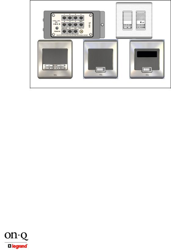
The following components (in addition to the 24VDC 1.25A 30 watt power supply) are typically utilized to make up the Selective Call Intercom System (see Figure 1).
Figure 1
SCI Module
Room
Unit
Patio Unit |
Door Unit |
Video Door Unit |
•Selective Call Intercom Distribution Module/s: These modules are typically installed in the On-Q enclosure. All Room Units, Patio Units and Door Units are connected directly to the Intercom Distribution Module via “home run” style single Cat 5e cabling. The Intercom Distribution Module also supplies power to the entire Selective Call Intercom System. Up to eight Units of any combination are supported by each Distribution Module and Modules may be cascaded three times, for a total system support of up to 32 Units.
•Selective Call Room Unit: Using the intuitive graphical user interface of its LCD display, this unit provides both basic intercom communication functions such as talk, talk to door (if Door Unit is installed), monitor and mute, and advanced functions such as dynamic sorting of users or monitoring multiple rooms at the same time. Up to 8 Selective Call Room Units can be installed per Selective Call Intercom Distribution Module and up to 32 per system.
•Selective Call Patio Unit: This unit also provides typical basic Room Unit functionality in a weather resistant wall mounted package for your patio. For security reasons, it does not support the door release function. There are no specific limits as to the mix of Room Units and Patio Units up to the physical limit of 8 per Distribution Module and 32 per system.
•Selective Call Door/Video Door Unit: This unit allows a visitor to the home to press the door chime button on the unit to notify the occupants of their presence. The occupants can then initiate a two-way communication with the visitor, see the visitor (Video Door Unit only) and even open the door (requires electronic door release device, not included). Up to 20 different door tones can be selected as the door tone that is played when the door chime button is pressed. There are no limits to the mix of Room, Patio and Door Units up to the physical limit of 8 per Distribution Module and 32 per system.
301 Fulling Mill Road, Suite G |
©Copyright 2008 by On-Q/Legrand, |
Middletown, PA 17057 |
Inc All Rights Reserved. |
(800)-321-2343 |
www.onqlegrand.com |
Page 2
III.Wiring Specifications
A.Specifications
Minimum cable rating: Category 5e UTP, 4 pair solid conductors (24 AWG),
100 ohm, 100 Mhz, General Purpose (CM), UL listed Maximum length per run: 325 feet (except where noted in documentation)
Termination standard: T568A
Terminating plug type: Solid Conductor RJ45
B.Guidelines
•Do not exceed 25 lbs. of force when pulling cable.
•Do not splice cables.
•Do not staple cables. Use wire ties with screw mounts to loosely secure cabling.
•Avoid running Cat 5 cable parallel to 120V/240V AC wiring or fixtures within 12 inches.
•Avoid “ganging” any intercom unit with a lighting dimmer switch. Maintain at least 12 inches of separation from dimmer switches.
•If you must cross AC wiring, do so at a 90 degree angle with at least 2 inches of separation.
•Maintain a minimum 1” bend radius.
•Do not untwist Cat 5 conductors more than 1/2” at any termination point.
•Keep cables away from HVAC ducts, or anything with sharp edges that could cause damage.
•Clearly label all cabling runs at both ends. Use the distance between your hand and your elbow as a guide to determine how far from the end of the cable to place the label.
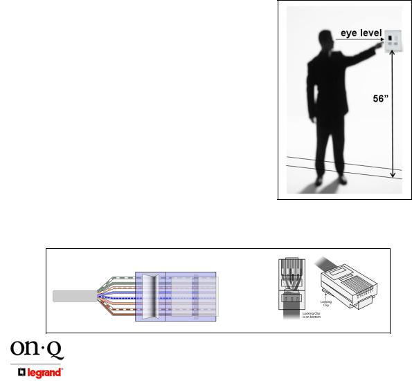
C.Unit Placement
To provide optimal display quality of the LCD on the |
Figure 2 |
Selective Call Room Unit, the two gang box that it is |
|
mounted in should be located for eye level operation. |
|
The bottom of the two gang box should be approximately |
|
56” from the floor see Figure 2). |
|
Carefully plan the placement of Room Units before |
|
rough-in to avoid any feedback issues that are |
|
associated with audio devices. |
|
•Avoid placing units back to back on a common wall to minimize the likelihood of any feedback issues. If units must be placed on both sides of a common wall, then place insulation in the back cavity of each electrical box.
•Do not place intercom units within the same room in the home.
•Avoid any situations where the speaker of a unit points to and has a clear line of sight to another unit’s microphone.
D.Termination Instructions
All components of the Selective Call Intercom System use RJ45 plugs terminated to the T568A wiring standard shown in Figure 3.
Figure 2 |
RJ-45 |
Figure 3 |
Pin
1 – White/Green
2 – Green
3 – White Orange
4 – Blue
5 – White/Blue
6 – Orange
7 – White/Brown
8 – Brown
301 Fulling Mill Road, Suite G |
©Copyright 2008 by On-Q/Legrand, |
Middletown, PA 17057 |
Inc All Rights Reserved. |
(800)-321-2343 |
www.onqlegrand.com |
Page 3

IV. System Wiring Overview
Figure 4
A.Pre-Wiring (Rough-In)
The rough-in of the Selective Call Intercom System should be completed during the construction phase of the home and prior to the installation of drywall. The following section will instruct you on the proper methods to pre-wire your cable and rough-in the openings for the various Selective Call Intercom System components.
Selective Call Room Unit(s)
The procedure to rough-in the Selective Call Room Unit(s) is as follows:
•Typically the Room Unit(s) will be installed on the same wall as the door to the room. Verify each Room Unit location with the homeowner before proceeding. Avoid installing Room Units in the same stud cavity on opposite sides of the wall to prevent feedback problems. If Room Units must be mounted back-to-back, place insulation in the back of both electrical boxes.
•The Room Unit mounts in a standard 2 gang electrical box. The use of an enclosed box rather than an open mud ring will help minimize the potential for feedback between units.
•Any UL approved metal or plastic gang box can be used.
•To avoid damage from debris during construction or after construction, use a gang box that will completely enclose the unit.
•To provide optimal display quality of the LCD on the Room Unit, the bottom of the 2 gang box should be installed at a height of 56” (see Figure 2).
•ONE Cat 5e run is required to operate the Room Unit.
•Run ONE Cat 5e cable from the 2 gang box directly to the enclosure where the Intercom Distribution Module will be installed. Label both ends of your cable run to indicate Room Unit number (ex: “Room Unit 5). Follow the wiring guidelines listed in this manual to ensure a quality cable installation.
301 Fulling Mill Road, Suite G |
©Copyright 2008 by On-Q/Legrand, |
Middletown, PA 17057 |
Inc All Rights Reserved. |
(800)-321-2343 |
www.onqlegrand.com |
Page 4
 Loading...